1
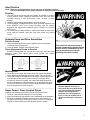
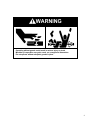
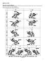
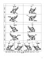
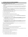
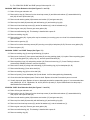
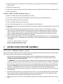
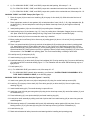
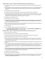
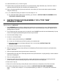
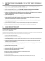
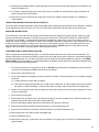
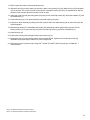
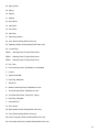
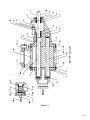
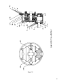
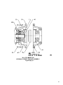
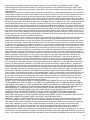
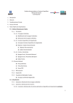
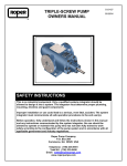
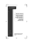
® 3611- 4722 GHB and BHB Supplement to G12-209 OWNERS MANUAL G12-436 04/08/04 SAFETY INSTRUCTIONS This is an industrial component. Only a qualified systems integrator should be allowed to design it into a system. The integrator must determine proper plumbing, mounting, driveline and guard components. Improper installation or use could lead to a serious, even fatal, accident. The system integrator must communicate all safe operation procedures to the end user(s). Before operation, fully understand and follow the instructions shown in this manual and any instructions communicated by the system integrator. No one should be allowed to operate or maintain this pump who has not been fully trained to work safely according to the configuration of the pump system and in accordance with all applicable government and industry regulations. Roper Pump Company P.O. Box 269 Commerce, GA 30529 USA Telephone: (706) 335-5551 TeleFAX: (706) 335-5490 Email: [email protected] www.roperpumps.com Good Practice NOTE: These are general guidelines and do not cover all possible situations. It is the responsibility of the system integrator to apply this product properly. Plumbing 1. The inlet pipe should be as short and straight as possible to minimize suction pressure losses. Excessive restrictions at the inlet can cause cavitation resulting in poor performance, noise, vibration, or pump damage. 2. Slope the inlet plumbing appropriately to avoid air pockets. 3. Plumbing weight, misalignment with the ports or thermal expansion can exert excessive force on the pump. Plumbing must be properly supported and aligned with expansion joints, if required, to minimize these forces. 4. To prevent over pressure situations, install a relief valve as close to the pump outlet as possible. Install the relief valve before any shut-off valves. ____________________________________________________________ Separate Pump and Drive Assemblies Driveline Guards 1. Assure adequate guards have been installed to prevent personnel contacting moving components. 2. Follow all OSHA, Federal, state and local codes. Over-pressure may burst pump or system components. Always include a relief valve in installation. Do not Check Alignment of Pump to Driveline Excessive misalignment can overload the pump input shaft and cause over pressurize pump or block premature failure. The figures below show parallel and angular discharge line while running. misalignments. Parallel Angular Mounting Base 1. Mount the unit on a rigid, heavy base to provide support and absorb shock. Bases should be designed for high rigidity, not just strength. 2. The pump feet were not designed for mounting to concrete and do not have enough contact area to prevent concrete from failing. When mounting to cement or concrete, use a steel base plate (supplied by others) to distribute the mounting stress over an area large enough to prevent the cement from failing. The base plate should be at least as thick as the pump feet. Grout it in place. ___________________________________________________________ Roper Pumps’ Close Coupled Drives Hydraulic drive units where the drive mounts directly to the pump • Driveline is not exposed and does not require guards. • Alignment between pump and drive line is maintained by the assembly. • Because the assembly absorbs reaction forces of the driveline, the mounting base does not need to be as robust. The level of rigidity and strength is determined by the piping stresses from the system. Injection Hazard: Do not try to stop a leak with your hand! Avoid any close contact with hydraulic fluid jets. Escaping fluid can penetrate skin, causing serious injury. In case of accident, see a doctor immediately for removal of fluid. 2 WARNING Operating without guards could result in serious injury or death. Machinery in operation can grab, crush, cut, mangle and dismember. Do not operate without adequate guards in place. 3 INSTALLATION Check Ports Versus Rotation: Make sure the inlet and discharge ports have been correctly plumbed corresponding to the direction of rotation and the relief valve, if present, is properly positioned. See following drawings for various configurations. Figure A 4 Figure B 5 1. RECOMMENDED TOOL LIST NOTE: Tools not furnished with pump. Tools for all Pumps: (1) (1) (1) (1) (1) (1) (1) Safety Glasses 9/16” Combination Wrench ¾” Combination Wrench 6” Adjustable Wrench CG-45 Snap-On Tool Bearing Puller 6” to 10” Three Square File Pliers Additional Tools for GHB Pumps: (1) ½” Combination Wrench Additional Tools for Pumps with an RV Type Relief Valve: (1) 7/16” Combination Wrench (1) 18” Pipe Wrench Additional Tools for Pumps with Flanges: (2) 15/16” Combination Wrench Additional Tools for Pumps with Shaft Packing: Packing Hook for .34” square packing rings Additional Tools for Pumps with Mechanical Seals: (1) 0400 External Retaining Ring Pliers Additional Tools for BHB and BH Pumps: (1) 5/16” Hex Key Snap-On is a registered trademark of Snap-On Tool Corporation 6 2. INSTRUCTIONS FOR PUMP DISASSEMBLY Refer to PUMP SECTIONAL DRAWINGS, (Figures 7.1 and 7.2) 1. Read WARNINGS before starting to disassemble pump. While disassembling pump, always inspect disassembled parts and adjacent parts to see if further disassembly is needed. Replace worn or damaged parts as required. 2. If you do not know which pump arrangement you have, collect nameplate data and refer to the Owners Manual for 3611-22 (G12-209), to determine what you have. Consult a Roper distributor or Roper Pump Company if you have any questions. 3. When cleaning or lubricating, use only cleaning solutions and lubricants that are compatible with products being pumped and with sealing elastomers. DO NOT use petroleum base products with seals with EPR elastomers. Use a nonpetroleum base lubricant with EPR elastomers. 4. Turn off pump and lock out energy source to driver. DO NOT proceed further with disassembly of pump if there is the slightest possibility that driver may be started. 5. If used, turn off and disconnect flush from mechanical seal. 6. Close inlet and discharge valves. 7. Remove guard and disconnect coupling between driver and pump. 8. Drain inlet and discharge lines. Disconnect lines from pump inlet and discharge. 9. Follow the procedure in the Owners Manual for 3611-22 (G12-209), INSTRUCTIONS FOR DRAINING PUMP. 10. A.) For 3600/4600 “GHBO” pumps, follow steps 11 – 20. B.) For 3600/4600 “BHB” pumps, go to Section 4, INSTRUCTIONS FOR DISASSEMBLY OF A TYPE “BHB” HYDRAULIC DRIVE. After disassembling hydraulic drive, return to this section and follow steps 11 – 20. C.) For 3600/4600 “GHB” pumps, follow steps 21 – 32. D.) For 3700/4700 “GHBO” pumps, follow steps 11 – 20. E.) For 3700/4700 “BHB” pumps, go to Section 4, INSTRUCTIONS FOR DISASSEMBLY OF A TYPE “BHB” HYDRAULIC DRIVE. After disassembling hydraulic drive, return to this section and follow steps 11 – 20. F.) For 3700/4700 “GHB” pumps, follow steps 42 – 53. 11. Remove two washer head cap screws (K) and eight hex head cap screws (L) securing faceplate (23A, B, C) to case (19A, B, C, D). Remove faceplate (23A, B, C). 12. Remove two dowel pins (J) from case. 13. Remove case gaskets (20). 14. On “BHB” and “GHBO” pumps, remove drive gear (34) and key (B) from drive shaft (32). 15. Remove idler gear (35) and key (B) from idler shaft (33). Remove idler shaft. 16. Remove two washer head cap screws (K) and eight hex head cap screws (L) securing backplate (6A, B) to case (19A, B, C, D). Separate parts. 17. Remove case gaskets (20) from opposite side of case (19A, B, C, D). 18. Remove two dowel pins (J) from opposite side of case (19A, B, C, D). 19. Remove drive key (A) from drive shaft (32). 20. A.) For 3600/4600 “GHB” gear reduction unit, follow steps 21 – 32. B.) For 3600/4600 “GHBO” and “BHB” pumps, follow steps 33 – 41. C.) For 3700/4700 “GHB” gear reduction unit, follow steps 42 – 53. 7 D.) For 3700/4700 “GHBO” and “BHB” pumps, follow steps 54 – 61. 3600/4600 ‘GHB” Gear Reduction Unit (See Figures 7.1 and 7.2) 21. Drain oil from gear reduction unit. 22. Remove drive key (A). Remove four hex head cap screws (U) and slide seal retainer (37) assembled with lip seal (39) off end of pinion shaft (42). 23. Remove seal retainer gasket (38) between seal retainer (37) and gear case (44). 24. Remove pinion shaft (42) assembly with ball bearing (41) and retaining ring (40). 25. Remove six hex head cap screws (W), twelve flat washers (X), and six lockwashers (Y). 26. Remove gear case (44). Remove gear case gasket (48). 27. Remove needle bearing (43). This bearing is installed with a press fit. 28. Remove retaining ring (45). 29. Remove drive gear (46). A gear puller may be necessary in removing gear, as a close fit is maintained between gear and shaft. 30. Remove drive gear key (Z). 31. Remove four socket head cap screws (AD) securing cover (49) to backplate (6A, B). Remove cover gasket (50). 32. Remove spacer (47). 3600/4600 “GHBO” and “BHB” Pumps (See Figure 7.1) 33. Remove retaining ring (3) securing ball bearing (2) in place. 34. Remove two locknuts (F) from square head bolts (G) securing packing gland (14) in place. Remove packing gland clip (13), packing gland (14), spring clip (15), and two square head bolts (G). 35. Remove packing rings (16) and packing washer (18). Remove lantern ring (17) if used. Packing hooks are commercially available to assist in removal of packing. 36. Remove drive shaft (32) along with ball bearing (2) and retaining ring (4) from backplate (6A, B). 37. Remove ball bearing (2) from drive shaft (32). 38. Remove retaining ring (4) from drive shaft (32). 39. Remove lip seal (5) from backplate (6A, B) and discard. It will be damaged during disassembly. 40. Clean drive shaft and adjacent parts. Examine shaft. Replace drive shaft if excessively worn or scored. 41. Visually inspect all parts. Replace all worn or damaged parts before reassembling pump. It is recommended that new gaskets (20, 22, 25, if applicable, 38, 48, 50) and new lip seals (5, 39) be installed each time the pump is disassembled and reassembled. 3700/4700 “GHB” Gear Reduction Unit (See Figures 7.1 and 7.2) 42. Drain oil from gear reduction unit. 43. Remove drive key (A). Remove four hex head cap screws (U) and slide seal retainer (37) assembled with lip seal (39) off end of pinion shaft (42). 44. Remove seal retainer gasket (38) between seal retainer (37) and gear case (44). 45. Remove pinion shaft (42) assembly with ball bearing (41) and retaining ring (40). 46. Remove six hex head cap screws (W), twelve flat washers (X), and six lockwashers (Y). 47. Remove gear case (44). Remove gear case gasket (48). 48. Remove needle bearing (43). This bearing is installed with a press fit. 49. Remove retaining ring (45). 8 50. Remove drive gear (46). A gear puller may be necessary in removing gear, as a close fit is maintained between gear and shaft. 51. Remove drive gear key (Z). 52. Remove four socket head cap screws (AD) securing cover (49) to backplate (6A, B). Remove cover gasket (50). 53. Remove spacer (47). 3700/4700 “GHBO” and “BHB” Pumps (See Figure 7.1) 54. Remove retaining ring (3) securing ball bearing (2) in place. 55. Remove drive shaft (32) along with ball bearing (2) and retaining ring (4) from backplate (6A, B). 56. Remove ball bearing (2) from drive shaft (32). 57. Remove retaining ring (4) from drive shaft (32). 58. If lip seal (5) is damaged or worn, remove from backplate (6A, B) and discard. 59. Remove two locknuts (F) from square head bolts (G) securing seal retainer (9) to backplate (6A, B). Remove seal retainer (9). 60. When removing following type of single seals (John Crane Type 21, Type 8-1, Type 9; Pac-Seal Type 21; Sealol Type 43), clean and lubricate drive shaft (32) prior to removing mechanical seal making sure that drive shaft is smooth and free from all burrs. Loosen setscrew (if present) on mechanical seal. Remove mechanical seal (11). Inspect sealing surfaces of stationary seal face and inspect rotating element. Replace as required. Remove retaining ring (12) from drive shaft (32), if applicable. 61. Visually inspect all parts. Replace all worn or damaged parts before reassembling pump. It is recommended that new gaskets (20, 22, 25, if applicable) and new lip seals (5, 39) be installed each time pump is disassembled and reassembled. John Crane is a registered trademark of John Crane Inc. Pac-Seal is a registered trademark of Pac-Seal Inc. Sealol is a registered trademark of EG & G Sealol. 3. INSTRUCTIONS FOR PUMP ASSEMBLY Refer to Section 7, PARTS LIST, (Figures 7.1 and 7.2). Refer to Section titled “Check Ports Versus Rotation” (Figures A and B) to assure proper configuration for pump rotation, port location, and relief valve position prior to assembling pump. 1. Visually inspect all parts during assembly. Replace all worn or damaged parts. Although they may appear reusable, it is recommended that new gaskets (20, 22, 25, if applicable, 38, 48, 50) and lip seals (5, 39) be installed when pump is being reassembled. • WARNING! Only use genuine Roper gaskets. Gasket thickness determines proper clearances. Always check quantity of gaskets removed and replace with exact quantity. Proper material must be used based on application. 2. When cleaning or lubricating, only use products that are compatible with product being pumped and elastomers within pump. DO NOT use petroleum base products with seals with EPR elastomers. Clean and lubricate parts with light oil unless EPR elastomers are used. Use a nonpetroleum base lubricant with EPR elastomers. 3. Mechanical seals are precision pieces of equipment. Use extreme care not to damage seal faces or elastomers during assembly. 4. Install two hollow dowel pins (J) on each side of case (19A, B, C, D). Place appropriate number of case gaskets (20) on faceplate side of case. Align faceplate (23A, B, C) on hollow dowel pins (J). Secure faceplate to case using two washer head cap screws (K) and eight hex head cap screws (L). 5. Place idler gear (35) into case bore. Install key (B) in keyway on idler shaft (33). Slide idler shaft into I.D. of idler gear. 9 6. A.) For 3600/4600 “GHBO,” “GHB,” and “BHB” pumps with shaft packing, follow steps 7 – 18. B.) For 3700/4700 “GHBO,” “GHB,” and “BHB” pumps with a standard mechanical seal, follow steps 28 – 38. C.) For 3700/4700 “GHBO,” “GHB,” and “BHB” pumps with a positive drive mechanical seal, follow steps 39 – 53. 3600/4600 “GHBO” and “BHB” Pumps (See Figure 7.1) 7. Place drive gear (34) into case bore. Install key (B) in keyway of drive shaft (32). Slide drive shaft into bore of drive gear. 8. Place appropriate number of case gaskets (20) on backplate side of case (19A, B, C, D). Align backplate (6A, B) on dowel pins (J). Secure backplate to case using two washer head cap screws (K) and eight hex head cap screws (L). 9. Install packing washer (18) over drive shaft (32) into packing bore of backplate. 10. Install packing rings (16) and lantern ring (17), if used, in packing bore of backplate. Stagger joints on each ring 180° apart. Seat each ring before adding next ring. Rings must not be tamped or seated too tightly. 11. Check drive shaft (32) for free movement after each ring is installed. 12. When packing box is sufficiently full to allow entry of packing gland (14) about ¼ of an inch [6 mm], reassemble packing gland. 13. Place one square head bolt (G) through each slot in backplate (6A, B) and through each hole in packing gland (14). Install packing gland (14) into packing box about ¼ of an inch [6 mm]. Slide packing gland clip (13) over square head bolts (G). Using two locknuts (F), secure packing gland (14) in place. Install spring clip (15) across square head bolts (G). Draw locknuts up evenly on packing to assure proper seating of packing (16), then loosen locknuts about ½ turn. DO NOT cock packing gland. This could cause binding or heating of drive shaft. 14. Install lip seal (5) in backplate (6A, B). 15. Install retaining ring (4) on drive shaft (32). 16. Install ball bearing (2) on drive shaft (32) and into backplate (6A, B) using retaining ring (3) to secure ball bearing (2) in place as shown in sectional drawing Figure 7.1. The fit between the drive shaft and ball bearing may be a light press fit. 17. Install spacer (47). 18. A.) For 3600/4600 “GHB” gear reduction unit, follow steps 39 – 47. B.) For 3600/4600 “BHB” hydraulic drive assembly, go to Section 5, INSTRUCTIONS FOR ASSEMBLY OF A TYPE “BHB” HYDRAULIC DRIVE, in the following pages. 3600/4600 “GHB” Gear Reduction Unit (See Figures 7.1 and 7.2) 19. Install cover gasket (50) and cover (49) on backplate (6A, B) using four socket head cap screws (AD). 20. Install key (Z) in keyway of drive shaft (32). Place drive gear (46) on drive shaft (32). Secure in place using retaining ring (45). 21. Install needle bearing (43). The needle bearing is a press fit bore. 22. Install gear case (44) and gear case gasket (48) using six hex head cap screws (W), twelve flat washers (X), and six lockwashers (Y). 23. Press ball bearing (41) onto pinion shaft (42) and install retaining ring (40). 24. Install pinion shaft assembly by sliding small end of pinion shaft into needle bearing (43) at same time gears are meshed together. 25. Slide bearing retainer (37) assembled with lip seal (39) and bearing retainer gasket (38) into place. Secure bearing retainer (37) to gear case (44) using four hex head cap screws (U) and four lockwashers (V). 26. Install drive key (A). 27. Read and understand all safety instructions and warnings before installing and operating pump. 10 3700/4700 “GHBO,” “GHB,” and “BHB” Pumps (Standard Mechanical Seal) (See Figure 7.1) 28. Place drive gear (34) into case bore. Install key (B) in keyway of drive shaft (32). Slide drive shaft into bore of drive gear. 29. Place appropriate number of case gaskets (20) on backplate side of case (19A, B, C, D). Align backplate (6A, B) on dowel pins (J). Secure backplate to case using two washer head cap screws (K) and eight hex head cap screws (L). 30. Install retaining ring (12) on drive shaft (32). 31. Carefully remove all burrs and sharp edges from shaft over which rotating element of seal will slide. 32. Lubricate drive shaft and mechanical seal bore with a compatible lubricant. Install mechanical seal (11) on drive shaft and position seal back against retaining ring (12). Care must be taken not to nick o-ring. Be sure lapped (polished) faces of stationary seal face and rotating element are together. 33. Install lip seal (5) in backplate (6A, B). 34. Install retaining ring (4) on drive shaft (32). 35. Install ball bearing (2) on drive shaft (32) and into backplate (6A, B) using retaining ring (3) to secure ball bearing (2) in place. The fit between drive shaft and ball bearing may be a light press fit. DO NOT damage seal parts while pressing ball bearing on drive shaft. 36. Place one square head bolt (G) through each slot in backplate (6A, B) and through each hole in seal retainer (9). Secure seal retainer against backplate using two locknuts (F). 37. Install spacer (47). 38. A.) For 3700/4700 “GHB” gear reduction unit, follow steps 19 – 27. B.) For 3700/4700 “BHB” hydraulic drive assembly, go to Section 5, INSTRUCTIONS FOR ASSEMBLY OF A TYPE “BHB” HYDRAULIC DRIVE, in the following pages. 3700/4700 “GHBO,” “GHB,” and “BHB” Pumps (Positive Drive Mechanical Seal) (See Figure 7.1) 39. Place drive gear (34) into case bore. 40. Install retaining ring (12) on drive shaft (32) to locate mechanical seal. 41. Carefully remove all burrs and sharp edges on shaft over which the rotating element of seal will slide. 42. Apply a compatible lubricant to seal I.D. and O.D. of drive shaft (32). 43. Slide rotating element of mechanical seal (11) onto drive shaft (32) before removing three or four clips that are taped to rotating element. Push rotating element back against retaining ring (12), tighten setscrews in seal, and remove clips that are taped to seal. 44. Slide faceplate end of drive shaft (32), with mechanical seal attached, into backplate (6A, B) through bore for ball bearing. 45. Place appropriate number of case gaskets (20) on backplate side of case (19A, B, C, D). Install key (B) in keyway of drive shaft (32). Slide drive shaft into bore of drive gear while aligning backplate (6A, B) on dowel pins (J). Secure backplate (6A, B) to case (19A, B, C, D) using two washer head cap screws (K) and eight hex head cap screws (L). 46. Lubricate o-ring on stationary seal face and seal chamber bore with a compatible lubricant. Slide stationary seal face over keyway end of drive shaft (32) and down to seal chamber. Be sure lapped (polished) face is toward rotating member of seal. Push stationary seal face into seal chamber. 47. Install lip seal (5) in backplate (6A, B). 48. Install retaining ring (40) on drive shaft (32). 49. Install ball bearing (2) on drive shaft (32) and into backplate (6A, B) using retaining ring (3) to secure ball bearing (2) in place. The fit between drive shaft and ball bearing may be a light press fit. DO NOT damage seal parts while pressing ball bearing on drive shaft. 11 50. Install antirotation pin (T) in locator ring (60). 51. Position locator ring (60) with antirotation pin (T) toward seal face. Align antirotation pin (T) with slot in back of stationary seal face and push into counterbore of backplate (6A, B). 52. Place one square head bolt (G) through each hole in seal retainer (9). Secure seal retainer against backplate using two locknuts (F). 53. A.) For 3700/4700 “GHB” gear reduction unit, follow steps 19 – 27. B.) For 3700/4700 “BHB” hydraulic drive assembly, go to Section 5, INSTRUCTIONS FOR ASSEMBLY OF A TYPE “BHB” HYDRAULIC DRIVE. 4. INSTRUCTIONS FOR DISASSEMBLY OF A TYPE “BHB” HYDRAULIC DRIVE Refer to Section 7, PARTS LIST. 1. Read WARNINGS before starting to disassemble hydraulic drive components from pump. While disassembling, always inspect disassembled parts and adjacent parts to see if further disassembly is needed. Replace worn or damaged parts as required. 2. Turn off pump and lock out energy source to hydraulic motor. DO NOT proceed further with disassembly of pump if there is the slightest possibility that hydraulic motor may be started. 3. Close inlet and discharge valves. 4. If pump is to be disassembled: A.) Refer to pump sectional drawing for “GHBFORV”. B.) If used, turn off and disconnect flush for packing or mechanical seal. C.) Follow the procedures in the Owners Manual for 3611-22 (G12-209), INSTRUCTIONS FOR DRAINING PUMP. D.) Disconnect lines from pump inlet and discharge. 5. Remove six socket head cap screws (AE) and six lockwashers (AF) that secure bracket (51) and bracket (52) together. Slide apart. 6. Remove cap screws that secure hydraulic motor to bracket (52). 7. Rotate bracket (52) until hole for loosening setscrew lines up with setscrew in coupling half (54). Loosen setscrew and remove coupling half. 8. Remove coupling spider (55). 9. Rotate drive shaft of pump (32) until setscrew in coupling half (53) lines up with hole for loosening setscrew. Loosen setscrew. Remove retaining ring (45) from drive shaft and remove coupling half. 10. Remove drive key (Z). 11. Remove four socket head cap screws (AD) that secure bracket (51) to backplate (6A, B). Remove bracket. 12. For further disassembly of the pump, refer to Section 2, INSTRUCTIONS FOR PUMP DISASSEMBLY, steps 1 – 20. Also, refer to steps 33 – 41 for pumps with packing, or steps 54 – 61 for pumps with mechanical seals. 12 5. INSTRUCTIONS FOR ASSEMBLY OF A TYPE “BHB” HYDRAULIC DRIVE 1. Refer to Section 3, INSTRUCTIONS FOR PUMP ASSEMBLY, steps 1 – 5. For installing packing, refer to steps 7 – 18. For installing mechanical seal, refer to steps 28 – 38. 2. Refer to sectional drawing (Figure 7.3) for TYPE “BHB” HYDRAULIC DRIVE COUPLING ASSEMBLY. 3. Secure bracket (51) to backplate (6A, B) using four socket head cap screws (AD). 4. Install key (Z) in shaft keyway. Place coupling half (53) on drive shaft (32). Install retaining ring (45). Rotate drive shaft (32) until setscrew lines up with hole in bracket (52), then tighten setscrew. 5. Install coupling spider (55). 6. Place bracket (52) onto pilot of hydraulic motor. DO NOT secure bracket into place at this time. 7. Place coupling half (54) onto shaft of hydraulic motor to dimension shown. Rotate bracket (52) until hole in bracket lines up with setscrew on coupling half. Tighten setscrew. 8. Rotate bracket on motor to line up motor mounting holes with bracket holes. Secure bracket (52) to hydraulic motor using appropriate fasteners. 9. Secure bracket (52) to bracket (51) using six socket head cap screws (AE) and six lockwashers (AF). 10. Read and understand all safety instructions and warnings before installing and operating pump. 6. GEAR REDUCTION UNIT ALIGNING GHB PINION SHAFT HEIGHT Refer to Section 7, PARTS LIST. The pinion shaft of the GHB gear reducer can be positioned at any location over a full 360°. This must be done before the gear reducer oil is added. The pinion shaft can be positioned in the following manner. 1. Loosen six hex head cap screws (W). 2. Rotate gear case (44) on six slots in cover (49). 3. If pinion shaft (42) cannot be moved to proper position at this point, remove six hex head cap screws (W) along with washers (X and Y). 4. Rotate pinion shaft to desired position. Reinstall and tighten six hex head cap screws (W) along with six flat washers (X) and six lockwashers (Y). 5. If six threaded holes in gear case (44) are not fully visible within cast slots on cover (49), gear reducer will have to be partially disassembled so that cover (49) can be rotated. 6. Slide gear case (44) off of cover (49). 7. Remove retaining ring (45) from end of pump drive shaft (32). 8. Remove drive gear (46). A gear puller may be necessary. 9. Remove four socket head cap screws (AD). 10. Rotate cover (49) 90° and reinstall and tighten four socket head cap screws. 11. Install drive gear (46) on drive shaft (32). 12. Install retaining ring (45). 13. Replace gasket (48) and slip gear case (44) complete with pinion assembly onto cover (49). 13 14. Rotate pinion to desired position. Install and tighten six hex head cap screws (W) along with six flat washers (X) and six lockwashers (Y). 15. If necessary, reposition plugs (AA), petcock (AC), and oil cup (AB). Oil cup should be at uppermost point and petcock at second hole from bottom. 16. Refill with oil to level of petcock (AC) using Gulf Senate 375, Mobile 600 W Cylinder Oil, or AGMA No. 7 compounded oil. LUBRICATION INSTRUCTIONS FOR INITIAL START-UP The oil cup (AB) is shipped separately to prevent breakage. Before placing the gear reduction unit in operation, install the oil cup (AB) and check the oil level in unit. The oil level should be maintained even with petcock (AC) at all times. SERVICING INSTRUCTIONS The oil should be clean and free from sludge at all times and should be changed at regular intervals. A drain plug (AA) has been provided near the bottom of the gear case (44) for this purpose. The oil (Gulf Senate 374, Mobil 600 W Cylinder Oil, or AGMA NO. 7 compounded oil) should be changed every 1000 hours or every four months, whichever comes first. Where operating conditions are severe, such as rapid rise and fall of temperature, or the atmosphere is moist or dusty, it may be necessary to change the oil every one or two months or sooner. The oil cup (AB) at the front of the gear case (44) is for filling the unit with oil and also serves as a breather. DO NOT allow the oil cup (AB) to become clogged. This could cause excessive pressure inside the gear case (44). CHANGING RATIO OF GEAR REDUCTION UNIT Refer to appropriate sectional drawing (Figure 7.2) showing internal construction of the gear reduction assembly. The internal construction for all ratios are identical, except for the drive gear (46) and pinion shaft (42), which determines the gear ratio of that particular unit. The drive gear (46) and pinion shaft (42) are interchangeable in pairs only. See GEAR RATIO CHART for ratios available. It is recommended that new gaskets (38, 48) and new lip seal (39) be installed each time unit is disassembled and reassembled. 1. Turn off pump and lock out energy source to driver. DO NOT proceed further with disassembly of gear reduction unit if there is the slightest possibility that driver may be started. 2. Drain oil from gear reduction unit. 3. If unit is assembled on a baseplate, directly connected to a motor, it will be necessary to remove flexible coupling as follows: A.) Loosen setscrew on motor half of coupling. B.) Slide motor coupling half towards motor to clear pump coupling half. (In case coupling cannot be removed in this manner, it will be necessary to remove either motor or pump in order to remove pump coupling half.) 4. Loosen six hex head cap screws (W) and rotate gear case (44) in slots provided until pump coupling half is clear of motor coupling half. 5. Remove pump coupling half. 6. Remove drive key (A). Remove four hex head cap screws (U) and four lockwashers (V). Slide seal retainer (37) assembled with lip seal (39) off the end of pinion shaft (42). 7. Remove seal retainer gasket (38) between seal retainer (37) and gear case (44). 8. Remove pinion shaft (42) assembly with ball bearing (41) and retaining ring (40). 9. Remove six hex head cap screws (W), twelve flat washers (X), and six lockwashers (Y). 10. Remove gear case (44). Remove gear case gasket (48). 11. Remove retaining ring (45). 12. Remove drive gear (46). A gear puller may be necessary in removing gear, as a close fit is maintained between gear and shaft. 14 13. Refer to gear ratio chart to select desired gear ratio. 14. Slide drive gear (46) on drive shaft (32) securing in place using retaining ring (45). Make sure key (Z) and spacer (47) are in place. The number of teeth or part number is stamped on drive gear (46). On standard units, last two numbers of part number represent number of teeth on gear. 15. Install gear case (44) and gear case gasket (48) using six hex head cap screws (W), twelve flat washers (X), and six lockwashers (Y). 16. Press ball bearing (41) onto pinion shaft (42) and install retaining ring (40). 17. Install pinion shaft assembly by sliding small end of pinion shaft into needle bearing (43) at same time gears are meshed together. 18. Slide bearing retainer (37) assembled with lip seal (39) and bearing retainer gasket (38) into place. Secure bearing retainer (37) to gear case (44) using four hex head cap screws (U) and four lockwashers (V). 19. Install drive key (A). 20. Install pump coupling half and tighten setscrews on drive key (A). 21. Rotate gear case (44) until coupling halves are accurately aligned. Tighten six hex head cap screws (W). Assemble coupling and tighten setscrew in motor coupling half. 22. Refill with oil to level of petcock (AC) using Gulf Senate 375, Mobil 600 W Cylinder Oil, or AGMA No. 7 compounded oil. Gulf is a registered trademark of Gulf Oil Company Mobil is a registered trademark of Mobil Oil Corporation 15 GEAR REDUCTION RATIOS AND CAPABILITIES Gear reducers are rated to transmit up to the horsepowers (kW) shown below. Three interchangeable gear ratios are available. 3611 THRU 4722 PUMPS NUMBER OF TEETH GEAR LOW HIGH RATIO SPEED SPEED GEAR GEAR 4.60 15 69 3.94 17 67 3.20 20 64 4.60 15 69 60 Hz OPERATION MOTOR RPM 580 870 PUMP RPM MAX HP ALLOWED 126 2.8 147 3.3 181 4.0 189 4.2 50 Hz OPERATION MOTOR RPM 485 760 PUMP RPM MAX KW ALLOWED 105 1.7 123 2.2 152 2.7 159 2.8 3.94 17 67 221 4.9 185 3.3 3.20 20 64 272 6.1 228 4.0 4.60 15 69 250 5.5 206 3.6 3.94 17 67 290 6.5 241 4.3 1150 950 3.20 20 64 360 8.0 296 5.3 4.60 15 69 380 8.5 315 5.6 3.94 17 67 445 10.0 368 6.6 3.20 20 64 545 10.0 453 6.6 4.60 15 69 750 10.0 620 6.6 1750 3450 1450 2850 16 7. PARTS LIST 2. Ball Bearing 3. Retaining Ring, Bearing Cage 4. Retaining Ring, Ball Bearing 5. Lip Seal (GHB) 6. Backplate A. Standard B. Jacketed 7. Bearing, Short 8. Bearing, Long 9. Seal Retainer 11. Mechanical Seal 12. Retaining Ring, Mechanical Seal 13. Packing Gland Clip 14. Packing Gland 15. Spring Clip 16. Packing Ring 17. Lantern Ring (Not Shown) 18. Packing Washer 19. Case A. ANSI Flanged – Straight Through B. Threaded Port Case – Right Angle C. Flanged Case – Right Angle D. Flanged Case – Straight Through 20. Case Gasket 21. Flange 22. Flange Gasket 23. Faceplate A. Plain B. RV Style Relief Valve C. Jacketed RV Style Relief Valve 24. Relief Valve Cap 25. Relief Valve Cap, Gasket 26. Adjusting Screw 27. Nut, Lock and Seal 17 28. Spring Guide 29. Spring 30. Poppet 31. Adapter 32. Drive Shaft 33. Idler Shaft 34. Drive Gear 35. Idler Gear 57. Expansion Washer 58. Cam, Double Setting Relief Valve only 59. Operating Piston, Double Setting Relief Valve only 60. Locator Ring WRN2 Warning Plate, RV Style Relief Valve WRN3 Warning Plate, RV Style Relief Valve WRN4 Warning Plate, RV Style Relief Valve B. Key, Gear E. Hex Head Cap Screw, Seal Retainer to Backplate F. Locknut G. Square Head Bolt H. Pipe Plug, Backplate J. Dowel Pin K. Washer Head Cap Screw, Endplates to Case L. Hex Head Cap Screw, Endplates to Case M. Hex Head Cap Screw, Flange Nut, Flange S. Pipe Plug, Faceplate T. Antirotation Pin AJ. Drive Screw AK. Ball Handle, Double Setting Relief Valve only AL. Stud, Double Setting Relief Valve only AM. Self Locking Nut, Double Setting Relief Valve only AN. Hex Head Cap Screw, Double Setting Relief Valve only 18 AP. O-Ring, Double Setting Relief Valve only Gear Reduction Assembly only 38. Bearing Retainer Gasket 39. Lip Seal 40. Retaining Ring, Ball Bearing 41. Ball Bearing 42. Pinion Gear and Shaft 43. Needle Bearing 44. Gear Case 45. Retaining Ring, Drive Gear 46. Drive Gear 47. Spacer 48. Gear Case Gasket 49. Cover 50. Cover Gasket U. Hex Head Cap Screw, Bearing Retainer to Gear Case V. Lockwasher, Bearing Retainer W. Hex Head Cap Screw, Cover to Gear Case X. Flat Washer, Gear Case Y. Lockwasher, Gear Case Z. Key, Drive Gear AA. Pipe Plug, Gear Case AB. Oil Cup, Gear Case AC. Petcock, Gear Case AD. Socket Head Cap Screw, Cover to Backplate 19 Type BHB Hydraulic Drive Bracket Assembly only 51. Bracket Half, Pump 52. Bracket Half, Motor 53. Coupling Half, Pump 54. Coupling half, Motor 55. Spider Coupling AE. Socket Head Cap Screw, Bracket to Bracket AF. Lockwasher 20 Figure 7.1 21 Figure 7.2 22 3611-4722 MBHB,F,RV HYDRAULIC DRIVE COUPLING ASSEMBLY Figure FigFigure 7.3 23 8. INDEX A Aligning GHB Pinion Shaft Height, 13 – 14 Assembly Instructions All, 9 – 10 3600/4600 “GHBO,” 10 3600/4600 “BHB,” 10 3600/4600 “GHB” Gear Reduction Unit, 10 3700/4700 “GHBO” - Standard Mechanical Seal, 11 3700/4700 “GHBO” - Positive Drive Mechanical Seal, 11 – 12 3700/4700 “GHB” - Standard Mechanical Seal, 11 3700/4700 “GHB” - Positive Drive Mechanical Seal, 11 – 12 3700/4700 “BHB” - Standard Mechanical Seal, 11 3700/4700 “BHB” - Positive Drive Mechanical Seal, 11 – 12 Type “BHB” Hydraulic Drive, 13 C Conversions Changing Ratio of Gear Reduction Unit, 14 – 15 D Disassembly Instructions All, 7 – 8 3600/4600 “GHB” Gear Reduction Unit, 8 3600/4600 “GHBO,” 8 3600/4600 “BHB,” 8 3700/4700 “GHB” Gear Reduction Unit, 8 – 9 3700/4700 “GHBO,” 9 3700/4700 “BHB,” 9 Type “BHB” Hydraulic Drive, 12 L Lubrication Gear Reduction Unit, 14 M Mechanical Seals, Installation of a Positive Drive Seal (John Crane Type 8-1 and Type 9), 11 – 12 P Plumbing, 2 R Ratings Gear Reduction Unit, 16 Rotation Check Ports Versus Rotation, 4 – 5 T Tools, 6 24 TERMS & CONDITIONS AND LIMITED WARRANTY This agreement (this "Agreement"), consisting of these Terms and Conditions, and the associated Order Acknowledgement is binding upon Roper Pump Company, hereinafter "SELLER," and the customer, hereinafter "BUYER." By placing an order for a product with the Seller, the Buyer agrees to these Terms and Conditions of sale and acknowledges that the person placing the order has the authority to enter into the Order Acknowledgement on Buyer's behalf. LEGAL EFFECT: Except as expressly otherwise agreed to in writing by an authorized representative of Seller, the following terms and conditions shall apply to and form a part of any Order Acknowledgement. Seller may suspend its performance of any Order Acknowledgement if Buyer defaults in the performance of its duties under the Order Acknowledgement or under any other agreement between the Buyer and Seller. ACCEPTANCE: The sale of goods and services is expressly conditional on Buyer's acceptance of Seller's terms and conditions as stated herein. Provided that Seller's terms and conditions have not been previously accepted by Buyer, Buyer's receipt of goods or services shipped under this Agreement constitutes acceptance of these terms and conditions. No additional, different or conflicting provisions proposed by Buyer are acceptable to Seller and are hereby specifically rejected, Seller being unwilling to sell goods on any terms conflicting with, limiting or modifying the terms hereof. Buyer shall not sell, transfer or otherwise provide any goods to another for resale without the prior, written authorization of Seller. Seller reserves the right to sell and to authorize other entities to sell such goods through all means and channels of distribution and in competition with Buyer. Buyer acknowledges that it has no authority to bind or contract in the name or for the account of Seller, to create any liability against Seller or to exert any direction or control over Seller's personnel. CHANGES: This Agreement and the associated Order Acknowledgement constitutes the entire agreement between Seller and Buyer with respect to the subject matter thereof, and supersedes all prior oral or written agreements. This Agreement and the associated Order Acknowledgement may not be amended or modified, except by a further written agreement signed by an authorized representative of Seller. Seller reserves the right to make reasonable changes to an Order Acknowledgement, including changes as to packaging, testing, specifications, designs and delivery schedules. The terms and conditions of any purchase order or other instrument issued by Buyer or its agent in connection with this Agreement and the associated Order Acknowledgement or any goods sold thereunder that is in addition to or inconsistent with the terms and conditions of this Agreement or the associated Order Acknowledgement are null and void and shall not be binding on Seller. Buyer's changes made after formation of this Agreement that affect the schedule or requirements for services or otherwise affect the scope of this Agreement shall be submitted in writing by Buyer and shall become binding only if approved in writing by Seller's cognizant representative. All charges and delays resulting from such changes shall be solely determined by Seller and shall be binding upon Buyer. TERMINATION, SUSPENSION, AND CANCELED ORDERS: Provided that Seller receives adequate written notice from Buyer, Buyer may terminate or suspend performance at Buyer's convenience subject to all reasonable charges, which charges shall be solely determined by Seller. Buyer cannot cancel or alter Orders without the Seller's written consent. If Seller grants such consent, Buyer will reimburse Seller for all of Seller's losses and expense caused by such cancellation or alteration, including without limitation all of Sellers additional costs caused by changes in design or specifications, or by product revisions, and all incidental and consequential damages incurred by Seller as a result of such cancellation or alteration. No goods may be returned to Seller except with Seller's written consent. Title in a returned good will pass when Seller takes possession of the returned goods. CREDIT: The amount of credit offered by Seller to Buyer is contingent upon Seller's opinion of Buyer's capacity, ability, and willingness to promptly pay for goods and services received under the terms of this Agreement. Provided that, in Seller's opinion, there is a material adverse change in Buyer's financial condition and/or Buyer has not, within the agreed time, fully paid for goods and services previously supplied under this and/or another Agreement(s) with Seller, Seller reserves the right to revoke Buyer's credit and/or suspend performance on this and/or other orders for goods and services. PAYMENTS: Standard terms for customers who qualify for credit net 30. A monthly service charge of 1.5% may be charged on amounts owed by Buyer to Seller that have not been paid within by the due date, subject to the maximum amount permitted by law. TAXES. Buyer assumes exclusive liability for any and all taxes, tariffs, fees, duties, withholdings or like charges, whether domestic or foreign, now imposed or hereafter becoming effective ("Taxes") related to the goods and its purchases from Seller, including without limitation, federal, provincial, state and local taxes, value-added taxes, goods and services taxes, stamp, documentary, excise or property taxes, duties and other governmental charges. TITLE AND LIEN RIGHTS: The equipment will remain personal property, regardless of how it is installed or affixed to any realty or structure. After delivery to Buyer, Seller will have all such rights, including security interests and liens, in the equipment as lawfully may be conferred upon Seller by contract under any applicable provision of law. Buyer agrees to cooperate fully with Seller in the filing of any financing statements, including Uniform Commercial Code (UCC) filings or 25 other documents necessary to perfect such interests and liens. If Buyer defaults in its obligations under the Order Acknowledgement before the price (including any notes given therefore) of the equipment has been fully paid in cash, Seller may take any and all actions permitted by law to protect its interests including, where permissible, repossession of such equipment. SHIPMENTS: All sales are Ex-Works Factory (as such term is defined by the International Chamber of Commerce as of the date hereof). Shipping contracts made by Seller shall be to Buyer's account. All claims for loss or damage after risk of loss has passed to Buyer shall be filed by Buyer with the carrier. Buyer shall be liable to Seller for the full price of the goods, irrespective of loss or damage in transit. Seller shall not be required to provide freight cost receipts to Buyer at the time of invoice. Buyer shall bear all risk and expense for delivery of goods, including without limitation, shipping, loading, unloading, storage, freight, and insurance. Goods may be shipped to Buyer in whole or in part. Title to goods shall pass to Buyer when delivered to the carrier or the Buyer, whichever occurs first, even if the goods are shipped freight prepaid. Among other things, a signed delivery receipt or bill of lading will constitute proof of delivery. The choice of carrier is made solely at the discretion of Seller, and Seller makes no representation as to the acceptability of a particular carrier. Except when Seller expressly agrees in writing, Seller does not guarantee shipment or delivery by a certain date or time, although Seller will strive to deliver goods by the date that it may communicate to Buyer. Seller shall not be liable to Buyer, or any other person, for any loss or damage of any kind which results from delay in shipment, delivery, or failure to give notice of delay, whether or not such delay was caused by Seller or otherwise. Seller reserves the right to backorder any goods and to ship from backorder in such order as Seller determines. LIMITED WARRANTY: Seller warrants, to its original Buyer, that goods manufactured by Seller are free from defects in material and workmanship for 12 months from date of shipment (except for specified products with warranties that supercede this limited warranty. Please consult factory for these products). The Buyer hereby acknowledges and agrees, though free from defects in material and workmanship at the time of shipment, that the useful life of goods manufactured by Seller will vary depending upon the Buyer's frequency of use, application, and other factors, with regard to such goods. In that respect, notwithstanding any other provision to the contrary in the Agreement, these Terms and Conditions, or the Order Acknowledgement, the Seller specifically does not warrant the useful life of any product. If a failure to conform to specifications or a defect in materials or workmanship is discovered within this period, Seller must promptly be notified in writing within thirty (30) days, which notification, in any event must be received no later than 12 months from the date of shipment. Within a reasonable time after such notification, Seller will correct any failure to conform to specifications or any defect in materials or workmanship, or in lieu of such repair, and at its sole option, shall replace the equipment. THE ABOVE ARE THE BUYER'S EXCLUSIVE REMEDIES FOR BREACH OF WARRANTY. Seller does not warrant: (a) defects caused by failure to provide suitable installation environment for the product, (b) damage caused by use of the product for purposes other than those for which it was purchased, (c) damage caused by disasters such as fire, flood, wind, and lightning, (d) damage caused by unauthorized attachments, or modification, (e) any other abuse or misuse by the Buyer, including improper installation; or (f) goods which have been damaged or altered by Buyer or its customers. Each good sold by Seller to Buyer shall be deemed to be without defect and in conformity with its specifications and the terms of this Agreement and the associated Order Acknowledgement even though reasonable variances may exist. As a result, Seller cannot and does not guarantee that goods sold hereunder, whether in whole or in part, will exactly match in specification or otherwise, and Buyer acknowledges that reasonable variance is permissible. Additionally, Seller shall have no liability if a good does not conform to any applicable state, county or local ordinance, as the conformity of a good to each state, county and local ordinance is the sole responsibility of the Buyer. Seller reserves the right to change its goods and the components of its goods without prior notice to Buyer, although in circumstances where an order from Buyer has been accepted by Seller, Seller will use commercially reasonable efforts to ensure that such change will not affect performance of the good in a materially adverse manner. EXCEPT AS SET FORTH ABOVE AND TO THE MAXIMUM EXTENT PERMITTED BY LAW, SELLER MAKES NO OTHER WARRANTIES FOR A PRODUCT OR UNDER THIS AGREEMENT OR ANY ORDER ACKNOWLEDGEMENT AND HEREBY DISCLAIMS ALL OTHER WARRANTIES, EXPRESS OR IMPLIED, INCLUDING BUT NOT LIMITED TO THE WARRANTY OF FITNESS FOR A PARTICULAR PURPOSE OR USE, AND INCLUDING THE WARRANTY OF MERCHANTABILITY. IN NO CASE SHALL SELLER BE LIABLE FOR ANY SPECIAL, INCIDENTAL, OR CONSEQUENTIAL DAMAGES BASED UPON ANY LEGAL THEORY, INCLUDING BUT NOT LIMITED TO LOSS OF PROFITS, LOSS OF SAVINGS OR REVENUE, LOSS OF USE OF THE PRODUCT OR ANY ASSOCIATED EQUIPMENT, COST OF CAPITAL, COST OF ANY SUBSTITUTE EQUIPMENT, FACILITIES OR SERVICES, DOWNTIME, THE CLAIMS OF THIRD PARTIES INCLUDING CUSTOMERS, INJURY TO PROPERTY AND, UNLESS PRECLUDED UNDER APPLICABLE STATE LAW, BODILY AND PERSONAL INJURY. INDEMNITY; LIABILITY LIMITATION: Buyer hereby agrees to indemnify, reimburse in full, defend and hold harmless Seller, its subsidiaries, affiliates, officers, directors, personnel and agents from and against any and all liability, claims, suits, actions, losses, costs or expenses including (without limitation) reasonable attorneys' fees relating to or arising out of any claim or demand (a) for any Taxes or related penalties and interest, (b) due to Buyer's breach of the Order Acknowledgement; (c) that Buyer's customers or a third party may make against Seller based upon or arising from damage due to the acts and/or omissions of Buyer or due to the installation of the goods; (d) for infringement or misappropriation of a third party's intellectual property rights based upon Seller's incorporation of any designs, formulas or specifications in any goods where such designs, formulas or specifications have been specifically ordered or requested by Buyer. To the maximum extent allowable under applicable law and excluding those liabilities that by law Seller cannot limit 26 or disclaim, (i) Seller's aggregate liability arising from or relating to this Order Acknowledgement or goods, regardless of the cause of action asserted, is limited to the amount paid by Buyer to Seller for the applicable goods and (ii) Seller shall not be liable for any special, incidental, consequential, indirect, or punitive damages, including without limitation, lost revenues, loss of use of the goods, loss resulting from improper storage, processing, padding/cushion, delay in delivery or shipment or errors in shipment or labeling, loss of data, or the cost of any substitute goods or related equipment, even if Seller has been advised of the possibility of such damages. EXPORT RESTRICTIONS: Buyer shall not export or re-export goods in violation of any applicable laws or regulations of the United States or the country in which Buyer obtained them. CONFIDENTIAL INFORMATION. During the term of this Agreement and the associated Order Acknowledgement and for the longer of (a) three (3) years following its termination and (b) for such Confidential Information of Seller that is a Trade Secret of Seller as defined by applicable law, for the life of such Seller Trade Secret, Buyer agrees to receive and hold Confidential Information of Seller in trust and in strictest confidence and shall not use, reproduce, distribute, disclose or otherwise disseminate any Confidential Information except as necessary to perform its obligations hereunder. Disclosures of the Confidential Information may be made only to Buyer's employees and agents who have a specific need to know and are subject to confidentiality restrictions at least as restrictive as those contained herein. "Confidential Information" means confidential information relating to the business, products and services of Seller which is or has been disclosed to Buyer, and which has value to Seller and is not generally known to Seller's competitors, including (without limitation), information regarding the specifications provided to Buyer by Seller and Seller's product plans, designs, costs, prices, finances, marketing plans, business opportunities, personnel, R&D activities and know-how. CONTROLLING LAW: This Agreement and the associated Order Acknowledgement entered into hereunder shall be governed and construed in accordance with the laws of the State of Georgia and of the United States of America without reference to any conflicts of law principles; the parties submit themselves to the jurisdiction of the federal and state courts located in Jackson County, Georgia, which shall have exclusive jurisdiction of any disputes arising hereunder, and the parties waive any objection to venue therein. The United Nations Convention on Contracts for the International Sale of Goods, the Uniform Law on the Formation of Contracts for the International Sale of Goods, and any applicable international discovery and service of process conventions shall not be applicable. In the event legal action is undertaken by Seller to collect any amounts due to Seller by Buyer hereunder and if Seller prevails in such action, then Buyer shall reimburse Seller for its reasonable attorney fees and costs incurred in conjunction with such action, which amount shall not exceed the maximum amount allowed by law of the forum in which such action is brought. ASSIGNMENT: Neither this Agreement nor any associated Order Acknowledgement may be assigned by the Buyer, or its contents publicized by the Buyer, without the written consent of Seller. Seller shall have the right to assign, transfer or sublicense all or any part of this Agreement or any associated Order Acknowledgement to another at any time and without the consent of Buyer. MISCELLANEOUS: The various provisions of this Agreement and any associated Order Acknowledgement are severable, and any determination of invalidity or unenforceability of any one provision hereof shall no bearing on the continuing force and effect of the remaining provisions hereof. This Agreement and any associated Order Acknowledgement and the terms and conditions contained herein constitute the entire understanding of the parties with respect to the purchase and sale of the goods, and any prior agreements, with respect thereto, whether written or oral, are superseded hereby. This Agreement and any associated Order Acknowledgement shall be binding on the parties and their respective successors and any permitted assigns. ELECTRONIC DATA INTERCHANGE. The parties may execute a Order Acknowledgement by transmitting and receiving the data contained in the Order Acknowledgement electronically rather than in paper form. To provide the legal validity and enforceability of such Order Acknowledgement, the parties further agree that the data transmitted herein will be considered "in writing" and to have been "signed." The parties agree not to contest the validity or enforceability of a Order Acknowledgement because of the electronic origination, transmission, storage or handling of such Order Acknowledgement. Any computer printout of the data contained in the Order Acknowledgement will be considered an "original" when maintained in the ordinary course of business and will be admissible as between the parties to the same extent and under the same conditions as other business records maintained in documentary form. The parties agree to properly use those security procedures which are reasonably sufficient to ensure that a transmission of the data contained in a Order Acknowledgement is authorized and to protect its business records and data from improper sources. 27