1
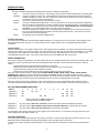
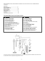
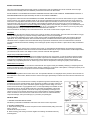
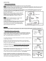
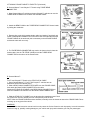
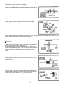
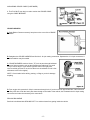
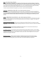
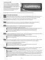
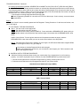
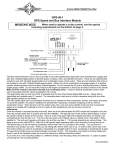
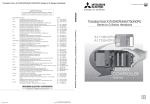
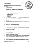
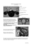
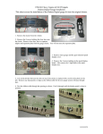
CRS-2000 & CRS-3000 Cruise Control System Introduction You have purchased one of the finest Cruise Control Systems on the market. The Cruise Control features: Enhanced Adaptability Enhanced Features Works with 3, 4, 5, 6 or 8 Cylinders Select ECM, AC Generator, Magnets, or Pulse Sender as Speed Signal Source Quiet Operation Allows more Mounting Locations Select Acceleration Rate Selectable Gain Control Manual or Automatic Transmission Capability Compatible with Distributorless Ignition System Easier Installation Modular Design Removable Wiring Harness with Locking Device Redesigned Water Sealing Neutral Safety Switch (NSS) Compatible Cruise Engaged Output (Ground Signal When Engaged) Self Diagnostic Improved Operation No Vacuum Required Smaller Module Single Unit Mounting Connectors with Positive Contact and Lock No Clutch Switch Needed (except Diesel) Additional Throttle Hardware Included in Kit Compatible with Neutral Safety Connections Closer, More Accurate Control of Set Speed Accurate Coast/Reduce Speed Tap-Up, 1 MPH per tap Tap-Down, 1 MPH per tap Controlled Resume Rate Here is an overview of the wiring diagram: Please Note: If you are using L.E.D. taillights please wire in a relay as shown on page 3 to allow for proper Cruise Control operation. -1- Additional Notes: Wiring Information: The wire connections that you will need to make into your vehicle are as follows: RED: BROWN: BLACK: VIOLET: BLUE: GRAY: Connect to constant 12 volt source. This should go to the fused terminal that feeds power to the brake lights. Connect to switched 12 volt source. This should be connected to an accessory terminal of the fuse panel capable of supplying 10 amps. This wire should have 12 volts when the ignition key is in the accessory and run positions, but not in the off or start positions. Connect to a good ground point on the chassis or fire wall. Connect to cold side of brake light switch. This wire should have 12 volts only when the brake is depressed. When the brake is not depressed it should be grounding through the brake light bulbs. If the brake light bulbs are not connected or are burned out, the system will not operate. LED brake lights will not provide proper grounding. If you have LED brake lights, use a relay as shown on page 3. Connect to negative side of ignition coil. On GM HEI ignitions or MSD ignitions connect to TACH terminal. Do not route the BLUE tach wire and GRAY speed wires along side each other. The tach wire can cause interference with the speed signal wire. see following section on SPEED CONNECTION. Throttle connection: The Cruise Control installation manual provides detailed diagrams for connecting the servo to the throttle. These diagrams cover basic OEM factory throttle hook-ups. It may be necessary to use a slight variation of one of the diagrams with aftermarket carburetors. Control switch: There are various types of turn signal and dash mount control switches that are available. The type of control switch that we supply with the cruise control is a closed circuit type for a turn signal handle control and open circuit for dash mount switches. If you will be connecting to a factory GM 4 wire control switch, they are open circuit type. GM switches which do not have 4 wires are not compatible with this cruise control. Ford cruise control switches are not compatible with this cruise control. SPEED CONNECTION: When using a cable drive speedometer, the metal, 8,000 pulse per mile, speed pulse generator is placed in line with the cable. This can be done at either the transmission side or the speedometer side of the cable. The two wires from the sensor connect as follows: Systems with black and gray wires twisted together from the sensor: BLACK wire to ground, GRAY wire from sensor harness to GRAY wire from cruise harness. Systems with a gray cable with a red and black wire inside: BLACK wire to ground, RED wire from sensor harness to GRAY wire from cruise harness. When the cruise control is used with a Dakota Digital STR3B, STR4B, STR5B, STR6B, STR3C, STR6C, STR5D, STR6D, STR2000 display system the gray wire should be connected to the SPEED terminal on the display system control box. On the VFD3, VFD3X or VHX display systems, the gray wire should be connected to the 2K or SPD OUT terminal, (2K or 4K PPM signal), on the display system control box (please see VFD3/VHX instruction manual for changing between 2K and 4K). When the cruise control is being installed into a newer vehicle which does not use a speedometer cable consult the Vehicle Technical Information Guide supplied with the cruise. This will provide you with information on where to connect the gray wire. SETTING PROGRAMMING SWITCHES: Switch** Application 1 Application 2 Application 3 1 ON ON ON 2 3 ON 4 ON 5 6 7 ON ON 8 9 10 ON ON 11 ON ON ON 12 *ON *ON *ON * SW 12 will be OFF for HND-2 applications ** all other switches to the OFF position Application 1: Application 2: Application 3: 8cyl, Auto tranny, STR series control box, closed circuit control switch, 8K PPM pulse generator 8cyl, Auto tranny, VFD3, VFD3X or VHX control box (2K OUT/ SPD OUT), closed circuit control switch 8cyl, Auto tranny, VDO 3-wire pulse generator, closed circuit control switch The description of the switch functions are found on page 6 of the Cruise manual. If you experience a surging when the cruise control engages then turn switch number 1 off. TROUBLE SHOOTING: If the system fails to operate after making all of the proper connections, consult the self diagnostics procedure on page 16. The Diagnostics LED is located beside the programming switches, under the rubber plug on the actuator. In order for the cruise to regulate the speed properly, the car must be tested on the road and not with the tires elevated off the ground. -2- Please Note: If you are using L.E.D. taillights please wire a relay as shown here to allow for proper Cruise Control operation. Use Dakota Digital RLY-1, or any 5 pin SPDT normally open relay. When using the relay, the Violet must go to Pin 30 (RLY-1 Black) ONLY. Pin 86 (RLY-1 Red) is the only wire that now goes to the cold side of the brake switch. TROUBLE SHOOTING: If the system fails to operate after making all of the proper connections, consult the self diagnostics procedure on page 16. The Diagnostics LED is located beside the programming switches, under the rubber plug on the actuator. In order for the cruise to regulate the speed properly under load, the car must be tested on the road and not with the tires elevated off the ground. -3- Dakota Digital ELECTRIC CRUISE CONTROL UNIVERSAL APPLICATION, INSTALLATION, & OWNER’S MANUAL CONTENTS: PARTS LIST....................................................... 4 PARTS DIAGRAM.............................................. 4 SAFETY PROCEDURES ...................................5 HELPFUL HINTS................................................ 5/6 SWITCH SETTINGS........................................... 6 INSTALLATION ..................................................7 TROUBLESHOOTING.........................................16 WARRANTY.........................................................19 OPERATING INSTRUCTIONS ............................20 The Dakota Digital Cruise Control System Includes: Qty. 111111112212211- Description Qty. A 250-2316 CRUISE MODULE B 250-2317 CRUISE HARNESS C 250-3607 CRUISE CABLE D 250-2236 MODULE BRACKET E 250-3700 CABLE BRACKET 1 F 250-3425 CONVOLUTED TUBING (58”) 1 250-2214 HARDWARE PACKAGE (UNIVERSAL) 250-2232 HARDWARE PACKAGE (-G, GM KIT) G1 MODULE BOLT 2 G2 SELF-THREADING BOLT (M6 X 19) 4 G3 BEAD CHAIN 1 G4 BEAD CHAIN CONNECTOR G5 CONNECTOR COVER G6 LOOP CABLE (67MM) G7 THREE BEAD CONNECTOR Description 1- G8 EYELET CONNECTOR 1- G9 TIE STRAP (102MM) 10- G10 TIE STRAP (190MM) 1- G11 TUBE CLAMP (10MM) 1- G12 FLAG NUT (THREADED TUBE CLAMP) 2- G13 M5 NUT 1- G14 GM HATCLIP 2- G15 LOCKWASHER NUT (#10-32) 1- G16 COTTER PIN (2MM X 16MM) 1- G17 SNAP-IN ADAPTOR 1- G18 PUTTY SEALING 1- G19 ADAPTOR THROTTLE CLIP W/CABLE 2- G20 CONN, SELF-STRIP (16-22 AWG) 2- G21 CONN, SELF-STRIP (16-18 AWG) 2- G22 SCREW, ROUND HEAD (#10-32 X .5) CRS-2000 also includes a signal generator Your vehicle must have a VSS (Vehicle Speed Signal) wire or an available signal generator for installation of the Cruise Control. The CRS-2000 includes the appropriate signal generator in the kit. -4- SAFETY PROCEDURES This unit is a microprocessor based Cruise Control. It is designed for ease of installation and can be used with most cars, light trucks and vans. Carefully follow the installation procedures in this manual for best results. DO NOT INSTALL THIS SYSTEM ON A DIESEL POWERED VEHICLE WHICH HAS A MANUAL TRANSMISSION WITHOUT A DISENGAGEMENT SWITCH (Kit# 250-4206) ON THE CLUTCH PEDAL ASSEMBLY. Throughout the instructions there are WARNINGS, CAUTIONS, AND NOTES that are meant to make it easier for you to install the Cruise Control on your vehicle and make it safer to use. We have gathered these tips from people across the country who have informed us of their problems and solutions. Even with all these reports from the field, we cannot cover every condition which you might encounter; there are just too many different vehicle makes and models. We do our best to tell you how to handle most vehicles, but we must Depend on Your Good Judgment for dealing with the rest. Therefore, we believe you can understand why we strongly urge you to think carefully about what could happen to you, your passengers, and your vehicle if you use any tools, parts, fastening methods, routing or procedures which are not described in this manual. There is NO drain on the battery if the control switch is left on. The Cruise Control needs no regular service. WARNING Failure to follow the instruction manual could not only cause the system to work improperly, but could cause the throttle to hang up, possibly causing damage to your vehicle and injury and/or death to you and your passengers. If you question the applications of the Cruise Control, please consult the applicable application guide. Only install on approved applications. The product described in this manual was developed, manufactured and tested in line with recognized technical standards and is in compliance with the fundamental safety requirements. Nevertheless, there are residual risks! It is therefore important to read this manual before installing and connecting the product. Keep the manual in a place that is readily accessible at all times. Throttle Adaptor In order to cover certain vehicles with a universal cruise control, we have designed throttle adaptors for performance and safety. Consult current Application Guides and Vehicle Technical Information Guides to see if your vehicle needs a Throttle Adaptor before you install the Cruise Control. If an adaptor is listed, it must be used with that application. Target Group and Qualified Installation This description is intended for those persons who install the product in the motor vehicle. In order to be able to operate properly, the Cruise Control must be correctly installed. The system may therefore be installed and wired by persons who know and have understood the installation instructions of this manual and are familiar with automotive electrical and mechanical systems. Installation by nonqualified personnel can lead to injury to the driver or third parties, or damage to property or the environment. Modifications to the product The Cruise Control is designed, manufactured and tested with due regard to safety and reliability. Modifying or tampering with the product can affect its safety. This can lead to death, serious or slight injury to the driver or third parties, or damage to property or the environment. For this reason, the product must not be modified or tampered with! Inform the user Hand the Operating Manual for the cruise to the user. The Operation Manual is an integral part of the product! If the cruise has not been fitted with a clutch switch, Please inform the user that the engine speed briefly increases when the function is switched off via the clutch. WARNING The information in this manual has been carefully compiled through actual vehicle testing and manufacturers service manual research and to the best of our ability is accurate. However, we do not warrant the accuracy of this information against changes in vehicle design, the use or misuse of this information or typographical errors. It is the responsibility of the installer to verify the signal and color on the wire attachments prior to and after the installation of the Cruise Control to assure proper operation. We do not accept any responsibility for damage to the vehicle or injury to its occupants caused by the use of this information. Improper installation and/or connection to the incorrect wires could cause Cruise Control or vehicle malfunction, component damage, and or personal injury for you and/or your passengers. HELPFUL HINTS 1. BEFORE STARTING INSTALLATION: Familiarize yourself with the Installation Instructions and Cruise Control components. 2. MATING CONNECTORS: A. When disconnecting, hold connector and press the lock downward while pulling connectors apart. - Figure A CAUTION: Do not pull on wires. B. When inserting, push mating connectors together until locking mechanisms are firmly locked together. -5- 3. AIRBAG AND ANTI-THEFT RADIO: A. If vehicle is equipped with an Anti-Theft Radio, the radio code must be written down prior to disconnecting battery cable. The code must be reentered when the negative battery cable is reinstalled. B. If vehicle is equipped with an airbag (SRS), it is advisable to disconnect the negative battery cable. However, remember that some vehicles retain power to the airbag system when battery is disconnected. 4. REMOVAL OF NEGATIVE BATTERY CABLE: Disconnect the negative battery cable before installing the Cruise Control for safety precautions. Remember to reconnect the cable after installation. 5. ACCESSORY POWER: When installing the accessory power connection, make sure you use the appropriate connector at the fuse box, or damage to you vehicle’s fuse box and/or electrical system may occur. SWITCH SETTINGS The CRUISE MODULE must be programmed for the vehicle on which it is installed. The twelve (12) programming switches must be set according to the chart below in order for the Cruise Control to operate properly. Figure 1 NOTE 1: Both the VSS (Gray) and TACH (Dark Blue) wires must be connected. (The lone Gray wire will not be used if the Magnetic Sensor kit is used as it plugs direct to the “Optional Speed Sensor” plug). NOTE 2: If using an “Open Circuit” control switch with the Cruise Control, Switch number twelve (12) will have to be OFF. If you are unsure as to whether the control switch is “Open Circuit” or “Closed Circuit”, look at the label of the packaging in which the switch came. NOTE 3: If any of the twelve (12) switches need to be changed after installation of the Cruise Control, the control switch and the vehicle ignition must be in the OFF position; this is to allow the Cruise Control to RESET. The twelve (12) programming switches are located under the Black Rubber Grommet on back of the CRUISE MODULE. Figure 1 represents the twelve (12) programming switches for a vehicle characterized by: -Switch (1 & 2) Gain Sensitivity Fig.1 - ON=UP -Switch (3 thru 6) VSS Pulses Per Mile -Switch (7 thru 9) Engine Cylinder Setup Timer -Switch (10) Square/Sine Wave Input -Switch (11) Manual/Automatic Transmission -Switch (12) Closed/Open Circuit Control Switch Programming Functions: * VEHICLE’S COMPUTER (or 3 wire pulse generator) ** AUXILIARY VSS SOURCE (signal generator or magnet kit) -6- INSTALLATION 1) CRUISE MODULE MOUNTING NOTE: DO NOT MOUNT THE CRUISE MODULE IN THE FOLLOWING AREAS: * Under the fender, Under the vehicle, Directly to the engine, With the cable pointed down, Near sharp, hot or moving objects, Near ignition coil [No closer than 255mm (10”)], In the passenger compartment (could hear internal motor operating), Or where it will interfere with service checks. A. Select a possible location to mount your CRUISE MODULE, set the CRUISE MODULE unmounted in that area. The reason for leaving the CRUISE MODULE unmounted is to make sure the CRUISE HARNESS will reach the passenger compartment and the CRUISE CABLE will reach the throttle attaching point. B.Once you have selected a location, install the MODULE BRACKET to the the CRUISE MODULE with the two (2) MODULE BOLTS provided. It may be necessary to cut and bend the MODULE BRACKET to achieve a custom fit. NOTE: DO NOT OVERTIGHTEN! DAMAGE TO THE CRUISE MODULE WILL OCCUR IF THE BOLTS ARE OVERTIGHTENED. C. Mount the CRUISE MODULE in the spot you have selected using two (2) of the SELF-THREADING BOLTS provided in the kit. Be sure to set the programming switches located underneath the rubber grommet of the CRUISE MODULE before mounting the Cruise Control. WARNING Failure to follow the instruction manual could not only cause the Cruise Control to work improperly, but could cause the throttle to hang up, possibly causing damage to your vehicle and injury and/or death to you and your passengers. 2) MEASURING THROTTLE CABLE TRAVEL THIS IS A VERY IMPORTANT STEP. FAILURE TO DETERMINE THROTTLE CABLE TRAVEL COULD CAUSE DAMAGE TO YOUR VEHICLE AND/OR THE CRUISE CONTROL MODULE. MEASURE ONLY WITH THE ENGINE OFF. Note: The CRUISE CABLE moves 41mm (1-5/8”). To measure throttle travel, measure the distance from Position “A” (Idle) to Position “B” (Wide Open Throttle). A. Make a mark on the throttle cable when the throttle is in the idle position. B. Depress accelerator pedal and make a mark on the throttle cable when the throttle is in the wide open position. C. Measure the Distance “C” between the two marks. If the distance is greater than 41mm (1-5/8”), skip to step 3) ATTACHING CRUISE CABLE TO THROTTLE. If the distance is less 41mm (1-5/8”), continue on to the next step, Step D. D. If the throttle travel is less than 41mm (1-5/8”), you must add length to the CRUISE CABLE to provide slack. – No more than 1/8”. NOTE: Slack is the distance the CRUISE CABLE moves before the throttle starts to move. The less the slack, the better the operation. 1/8” maximum! E. Slide a CONNECTOR COVER on the throttle LOOP CABLE and on the CRUISE CABLE. Install a BEAD CHAIN CONNECTOR on the end of the LOOP CABLE and on the end of the CRUISE CABLE. The BEAD CHAIN CONNECTOR may need to be spread slightly for cable to enter. -7- MEASURING THROTTLE CABLE TRAVEL (Continued) F. Install the end bead of the BEAD CHAIN in each BEAD CHAIN CONNECTOR with a bead (or beads) between them to add additional length. The beads inside the BEAD CHAIN CONNECTORS do not add length. NOTE: Each bead of the BEAD CHAIN added between the BEAD CHAIN CONNECTORS will give you 7mm (.28”) of slack. Example: If your throttle travels 35mm (1-3/8”), you will need to add one (1) bead between connectors. G. After the BEAD CHAIN is installed, lightly crimp the BEAD CHAIN CONNECTORS without pinching the cables and center the CONNECTOR COVERS over the BEAD CHAIN CONNECTORS. NOTE: You must always use the CONNECTOR COVERS. 3) ATTACHING CRUISE CABLE TO THROTTLE This section will cover the proper ways to use the hardware available. Each method contains sample illustrations showing how the connector is used in an actual installation. It must be noted, however, that you should have an understanding of how each attachment method works so that a proper installation is achieved. There are five (5) different types of throttle connections. A. Pulley Assembly Using The LOOP CABLE B. Pulley Assembly Using T-BAR ADAPTOR C. Pedal Attachment. D. Ford™ Throttle E. General Motors™ and Chrysler™ Throttle Using THREE BEAD CONNECTOR A. Pulley Assembly Using The LOOP CABLE 1. On some vehicles it may be necessary to remove the air cleaner to access the throttle pulley segment. 2. Set the pulley segment in an OPEN throttle position, and remove the throttle cable from the pulley. 3. Hold the LOOP CABLE between the holes in each side of the pulley. Slide the barrel at the end of the throttle cable through the slotted hole, then through the LOOP CABLE and into the second hole. 4. Connect the LOOP CABLE to the CRUISE CABLE using the BEAD CHAIN CONNECTOR as follows: Slide a CONNECTOR COVER on the LOOP CABLE. Install a BEAD CHAIN CONNECTOR onto the LOOP CABLE and then onto the CRUISE CABLE. BEAD CHAIN CONNECTOR may need to be spread slightly for cables to enter. After the BEAD CHAIN CONNECTOR is installed, lightly crimp the connector without pinching the cables. Then slide the CONNECTOR COVER over the center of the BEAD CHAIN CONNECTOR. 5. To secure the LOOP CABLE to the throttle cable, punch a small hole in the CONNECTOR COVER and slide the TIE STRAP (102MM) through the hole and secure to the throttle cable. NOTE: Firmly tighten the TIE STRAP (102MM) and remove excess to prevent possible throttle interference. WARNING If the LOOP CABLE is not secured to the existing throttle cable, it could come out of the pulley segment possibly causing the throttle to be held in a partially open position. -8- ATTACHING CRUISE CABLE TO THROTTLE (Continued) B. Pulley Assembly (Dual) Using The T-BAR ADAPTOR 1. Remove air cleaner to expose the dual pulley segments. 2. Find the blank anchor that is located above the throttle anchor. Follow the instructions for anchoring the CRUISE CABLE. 3. Attach a BEAD CHAIN CONNECTOR onto the CRUISE CABLE. 4. Attach the T-BAR ADAPTOR to the top pulley segment. Slide the CONNECTOR COVER onto the T-BAR ADAPTOR. 5. Attach the T-BAR ADAPTOR to the BEAD CHAIN CONNECTOR. Make sure to slide the CONNECTOR COVER over the BEAD CHAIN CONNECTOR. C. Pedal Attachment 1. Select a TUBE CLAMP that fits around the top of the accelerator pedal shaft. Make sure the tabs of the TUBE CLAMP point away from the bulkhead. 2. Attach the BEAD CHAIN to the CRUISE CABLE with a BEAD CHAIN CONNECTOR. Make sure to use a CONNECTOR COVER. 3. After you determine the length of BEAD CHAIN needed to attach to the accelerator pedal shaft, cut BEAD CHAIN and attach to the EYELET CONNECTOR. Make sure to use a CONNECTOR COVER. 4. Put M5 BOLT through the holes in the TUBE CLAMP. Slide the EYELET CONNECTOR over the bolt. Thread LOCKNUT onto the bolt and tighten. D. Ford™ Throttle 1. Select a TUBE CLAMP that fits the throttle cable. Make sure the tabs of the TUBE CLAMP point away from the carburetor or air throttle, this will prevent the throttle from hanging. 2. Attach CRUISE CABLE to the EYELET CONNECTOR. NOTE: Use the CONNECTOR COVER. 3. Put the M5 BOLT through the holes in the TUBE CLAMP. Slide the EYELET CONNECTOR over the bolt. Thread the LOCKNUT onto the bolt and tighten. 4. Here is an example of a Ford ™ Throttle connection using the TUBE CLAMP. WARNING Failure to follow the instruction manual could not only cause the Cruise Control to work improperly, but could cause the throttle to hang up, possibly causing damage to your vehicle and injury and/or death to you and your passengers. -9- ATTACHING CRUISE CABLE TO THROTTLE (Continued) E. General Motors™ and Chrysler™ Throttle using THREE BEAD CONNECTOR. 1. Most General Motors™ vehicles and many Chrysler™ vehicles can use the THREE BEAD CONNECTOR to attach the CRUISE CABLE. 2. Attach the BEAD CHAIN to the THREE BEAD CONNECTOR. Secure beads by folding the metal tabs. 3. Remove clip or pin which retains throttle cable (and washer if provided) and install THREE BEAD CONNECTOR on the same side of throttle cable that the CRUISE CABLE will be anchored (this is necessary so that CRUISE CABLE and throttle cable will not cross). 4. The THREE BEAD CONNECTOR may need to be bent so that it clears the throttle cable. Use the TIE STRAP (102M) to hold the THREE BEAD CONNECTOR to the sleeve of the throttle cable. F. General Motors™ Ford™ and Chrysler™ Throttle using STUD-CLIP W CABLE 1. Some General Motors™, Ford™ and Chrysler™ vehicles have an attachment stud on the throttle pulley. 2. Slide a BEAD CHAIN CONNECTOR COVER over the CRUISE CABLE, then attach the Bead CHAIN CONNECTOR to the cable. Attach the STUD-CLIP W CABLE to the BEAD CHAIN CONNECTOR and slide the CONNECTOR COVER over the BEAD CHAIN CONNECTOR. 3. Slide the STUD-CLIP W CABLE over the throttle pulley attachment stud. Push the STUD-CLIP onto the vehicle stud until it snaps firmly onto the stud. NOTE: After the CRUISE CABLE has been attached, manually move the throttle to assure the CRUISE CABLE does not hang up on any part of the vehicle. WARNING Failure to follow the instruction manual could not only cause the Cruise Control to work improperly, but could cause the throttle to hang up, possibly causing damage to your vehicle and injury and/or death to you and your passengers. - 10 - ANCHORING CRUISE CABLE There are three (3) types of connectors used to anchor the CRUISE CABLE: A. SNAP-IN ADAPTOR B. General Motors™ Blank Anchor C. FLAG NUT A. SNAP-IN ADAPTOR 1. To use the SNAP-IN ADAPTOR, it will be necessary to form threads on the end of the CRUISE CABLE. This is easily accomplished by placing the LOCKWASHER NUT on the end of the CRUISE CABLE with your fingers. Then using an 11mm box end wrench and turning clockwise until the desired amount of threads have been formed. 2. After the threads have been formed, screw the SNAP-IN ADAPTOR onto the CRUISE CABLE. NOTE: Insulation on the CRUISE CABLE must extend past the end of the SNAP-IN ADAPTOR on all applications. 3. The SNAP-IN ADAPTOR snaps into the square hole of the CABLE BRACKET or snaps into an existing square hole on the vehicle (common on GM™ vehicles). B. General Motors™ Blank Anchor 1. To locate the blank anchor on General Motors™ vehicles, it is necessary to remove the air cleaner. The blank anchor is located above the throttle anchor. 2. This anchor is hollow except at one end. Use a 6.4mm (.25”) bit drill as shown: 3. Use the LOCKWASHER NUT to form threads on the end of the CRUISE CABLE. This is easily accomplished by placing the LOCKWASHER NUT on the end of the CRUISE CABLE with your fingers. Then use an 11mm box end wrench and turn clockwise until the desired amount of threads have been formed. - 11 - ANCHORING CRUISE CABLE (CONTINUED) 4. Insert the CRUISE CABLE through the blank anchor and thread the other LOCKWASHER NUT in place. If you do not use the other LOCKWASHER NUT, install a TUBE CLAMP 152mm-178mm from the anchor point. This will keep the CRUISE CABLE from backing out of the anchor. 5. The LOCKWASHER NUT can also be used if there is a pre-existing 6.4mm hole in a bracket on the vehicle or if it is possible to drill a 6.4mm hole in a bracket on the vehicle. C. FLAG NUT 1. Before using the FLAG NUT, it will be necessary to form threads on the end of the CRUISE CABLE. This is easily accomplished by placing the LOCKWASHER NUT on the end of the CRUISE CABLE with your fingers. Then use an 11mm box end wrench and turn clockwise until the desired amount of threads have been formed. 2. After the threads have been formed, screw the FLAG NUT onto the CRUISECABLE. 3. The FLAG NUT may be used to anchor the CRUISE CABLE to the existing throttle cable bracket. In some cases there is an existing hole, in other cases you can drill a 5mm (.20”) hole in the bracket. - 12 - ANCHORING CRUISE CABLE (CONTINUED) 4. The FLAG NUT may also be used to anchor the CRUISE CABLE using the CABLE BRACKET. CRUISE HARNESS A. Push Rubber Grommet securely into place on the cover of the CRUISE MODULE. B. Straighten the CRUISE HARNESS and find the 2- & 4-pin mating connectors. Separate the 2- & 4-pin connectors. A small screwdriver may be needed. C. CRUISE HARNESS needs a 19mm (.75”) hole to pass through bulkhead. You may find one nearby, such as the speedometer cable hole or a small one you can file larger. If you find the right size hole in the right place, remove vehicle grommet. If not, drill a 19mm hole in bulkhead. A hole a few millimeters to the left or slightly NOTE : Check inside before drilling, sawing, or filing so you don’t damage anything. D. From engine side, pass the 2-& 4-pin connectors through hole. If you do not hook up the Dark Blue TACH wire and the Gray VSS wire under the hood, pass them through to the inside of the vehicle, also. Reattach the 2-& 4-pin mating connectors and make the necessary wire connections. SEALING BULKHEAD Seal hole in bulkhead with SEALING PUTTY to avoid moisture from getting inside the vehicle. - 13 - CONTROL SWITCH INSTALLATION If your cruise control switch is the type which clamps on the turn signal lever, requires cutting the turn signal lever, or is mounted on the instrument panel, follow the instructions packaged with it. If you have a switch which replaces the complete original equipment turn signal lever, remove the existing lever and install the cruise control switch and lever assembly as instructed in the vehicle shop service manual. WIRING ATTACHMENTS TO VEHICLE Utilize the wiring information below to make the necessary wiring harness connections to your vehicle. CAUTION: Before making any wiring connections, be sure to disconnect your vehicle’s negative battery cable to avoid electrical shock and/or damage to the vehicle’s electrical system. Black - Ground Wire In order to find a good ground for the cruise system, find a vehicle ground point which is a clean unpainted metal surface. If the cruise control does not “see” ground at all times, it will not function. NOTE: Do not use the engine as a grounding point. Do not use the cable bracket as a grounding point. NOTE: To find a place to get electrical power you will need to ground one lead of your test light or volt-ohmmeter. Find electrical ground by turning ON the ignition switch and touching one lead to a “Hot” fused terminal at fuse panel; touch other lead to unpainted metal part of vehicle. The metal you touch, if it makes continuity, is ground. The bracket for the parking brake lever is usually a good ground. Turn the ignition OFF. Brown - Accessory Power Find a fuse at the fuse panel that supplies power to one of the vehicles accessories. It should be +12 volts when the key is ON and zero (0) volts when the key is OFF or in the START (CRANK) position. Red - Brake Positive “Hot” side of brake switch: Use the wire at the brake switch connector with constant +12 volts Violet - Brake Negative “Cold” side of brake switch: Use the wire at the brake switch connector with close to zero (0) resistance when brake is not pressed, and +12 volts or open resistance when brake is pressed. If you have LED tail lights or an LED brake light please refer to page 3 with the alternate wiring method with a relay. Dark Blue - Tachometer (TACH) Wire The TACH function is a safety feature of the Cruise Control. If a vehicle with an automatic transmission is accidentally “knocked” into neutral while the vehicle is in motion and the Cruise Control is active, the TACH wire, when connected, will disengage the Cruise Control before engine over-rev. If the TACH wire is not “hooked-up”, the cruise control will function; however the TACH over-rev safety feature will be inactive; this is dangerous and not recommended. Dakota Digital, INC. always recommends the attachment of the TACH wire. On a vehicle with a manual transmission, the TACH wire connection is not required only when CLUTCH DISENGAGEMENT SWITCH (Kit# 250-4206) has been installed; this will take into account the TACH over-rev safety feature. The TACH wire should be grounded when using a clutch disengagement switch to ensure that the wire does not introduce “trashy” signals into the system. - 14 - Gray - Vehicle Speed Sensor (VSS) Wire The Gray Vehicle Speed Signal (VSS) wire is how the Cruise Control “knows” how fast the vehicle is moving. The Pulses Per Mile/Kilometer (PPM/PPK) are a characteristic of the vehicle and must be set accordingly. If VSS cannot be located on the vehicle then an auxiliary road speed sensor must be used [Signal Generator or Magnet & Coil PickUp Kit (Kit # 250-4165) (Dakota Digital P/N SEN-4165)]. If you use an auxiliary speed sensor, plug it into auxiliary speed sensor connector and trim the Gray VSS wire short as not to pick-up any stray signals. In order to locate the VSS and TACH signals in your vehicle, consult a Vehicle Shop Manual. Light Green – Optional Neutral Safety (NSS) - (wire is taped at beginning of harness) The NSS function is an optional safety feature of the Cruise Control. If a vehicle with an automatic transmission is accidentally “knocked” into neutral while the vehicle is in motion and the Cruise Control is active, the NSS wire, when connected, will disengage the Cruise Control before engine over-rev. If the NSS wire is not “hooked-up”, the cruise control will function; but the Dark Blue tachometer wire must then be used. This light green wire terminates in the harness. Orange – Optional Enable Output (ENO) Wire - (wire is taped at beginning of harness) The ENO Function allows you to use the Cruise Control as a driver for an external L.E.D. The ENO Wire will supply a ground to an LED (the positive side of an LED has ignition power), when the system is engaged. This orange wire terminates in the harness. Auxiliary Speed Sensor Connector - This connector is utilized when the Gray VSS wire is not used as the vehicle speed source. Please contact Dakota Digital regarding the Magnet & Coil Pick-Up Kit should your particular installation require one. 4-Pin Switch Connector - This connector is utilized by the control switch. The control switch included with your purchase has a mating connector which plugs into this connector. 2-Pin Switch Connector - This connector is used in conjunction with the 4-Pin Switch Connector. The 2-Pin Switch Connector is utilized by certain control switches which require an additional power and ground source such as those containing an LED indicator light or optional Radio Frequency (RF) models. Dakota Digital does not carry the RF switches so this plug will not be used. Bulkhead Connectors - These connectors simplify the installation of the wiring harness through the engine bulkhead (firewall). Simply disconnect the connectors, run them through any 19mm (.75”) hole in the firewall (preferably near the steering column), and reconnect them once inside the passenger compartment. - 15 - TROUBLESHOOTING SELF DIAGNOSTIC TESTING PROCEDURE The Cruise Control is equipped with a Red Self Diagnostic Surface Mount Light Emitting Diode (LED) located underneath the rubber grommet on the CRUSE MODULE. Utilize the following Self Diagnostic Procedure to troubleshoot your cruise control if it does not function properly once installed. Carefully follow the procedures below to enter your cruise control into Self Diagnostic Mode. Step 1: Turn the cruise control switch OFF. Step 2: Turn the ignition to the OFF position. Step 3: Standard Control Switch (all except HND-2): Press and hold the RESUME/ACCEL slide switch while you turn the ignition switch to the ON position without starting the engine. Now release the RESUME/ACCEL slide switch. HND-2 Control Switch: Turn the ignition switch to the ON position without starting the engine, hold the RESUME/ACCEL button down while you turn the cruise control switch to the ON position. Step 4: The Diagnostic LED should be OFF at this time. You are now in Self Diagnostic Mode. Continue to follow the procedures below to test your cruise control switch, brake switch connections and VSS signal. Step 5: Press and Release the SET/COAST button. The LED should light each time the button is pressed and go out when it is released. If so, continue to Step 6; if not, go to Step 5a. a. Check steps to entering Diagnostic Mode and test again. b. Check Programming Switch# 12. It should be ON for a Normally Closed Circuit Control Switch and OFF for a Normally Open Circuit Control Switch. If set incorrectly, reset and reenter Diagnostic Mode. c. Check power to the CRUISE MODULE if none of the diagnostic commands are functioning. d. Check Cruise Control Switch. Step 6: Press and release the RESUME/ACCEL slide switch / button. The LED should light each time the slide switch / button is pressed and go out when it is released. If so, continue to Step 7; if not, go to Step 6a. a. Check steps to entering Diagnostic Mode and test again. b. Check power to the CRUISE MODULE if none of the diagnostic commands are functioning. c. Check Cruise Control Switch. Step 7: You will need a second person to help you perform this test. Press and release the Brake Pedal. The LED should light each time the brake is pressed and go out when it is released. If so, continue to Step 8; if not, go to Step 7a. a. Check steps to entering Diagnostic Mode and test again. b. Check power to the Red Brake Positive wire. c. Check power to the CRUISE MODULE if none of the diagnostic commands are functioning. d. Check Brake Switch Connector and wiring to brake switch. Step 8: A. Vehicle’s own computer as VSS source: Roll the vehicle at least two (2) meters forward or backward, the LED should flash and continue to flash at the same rate. If so, continue to Step 9; if not, go to Step 8Ai. i. Check steps to entering Diagnostic Mode and test again. ii. Check Programming Switch# 10. It should be ON for Square Wave Input. If set incorrectly, reset and reenter Diagnostic Mode. iii. Some vehicles need to be pushed more than two (2) meters. In that case, raise one (1) of the vehicle drive wheels (both drive wheels on a limited slip differential) and block the non drive wheels. Use a support stand for safety. Spin the drive wheel by hand as fast as possible. The LED should flash and continue to flash at the same rate. If so, continue to Step 9; if not, go to Step 8Aiv. iv. Either your VSS wire is incorrect or your connection is bad. Inspect your VSS connection and reenter Self Diagnostic Mode. - 16 - TROUBLESHOOTING Continued B. Auxiliary Speed Sensor ([SIGNAL GENERATOR or MAGNET & COIL PICK-UP KIT (KIT# 250-4165)] Raise one (1) of the vehicle drive wheels (both drive wheels on a limited slip differential) and block the non drive wheels. Use a support stand for safety. Spin the drive wheel by hand as fast as possible (You must spin the wheel at least 4.8 KPH (3 MPH) or faster in order to test an auxiliary speed signal.) The LED should flash and continue to flash at the same rate. If so, continue to Step 9; if not, go to Step 8Bi. i. Check steps to entering Diagnostic Mode and test again. ii. Check Programming Switch# 10. It should be OFF for Sine Wave Input. If set incorrectly, reset and reenter Diagnostic Mode. Step 9: Your Cruise Control 2 has successfully passed the Self Diagnostic Testing Procedure. If it still does not function, test your TACH signal. X. TACH SIGNAL TESTING PROCEDURE Step 1: Turn the cruise control switch OFF. Step 2: Turn the ignition to the OFF position. Step 3: Standard Control Switch (all except HND-2): Press and hold the RESUME/ACCEL button while you turn the ignition switch to the ON position and start the engine. Now release the the RESUME/ACCEL slide switch. HND-2 Control Switch: Turn the ignition switch to the ON position and start the engine, hold the RESUME/ACCEL button down while you turn the cruise control switch to the ON position. Step 4: The Diagnostic LED should be flashing. Rev the engine, the LED should flash faster at higher RPM’s. If so, your TACH signal is valid, if not, go to Step 4a. a. Check steps to entering Diagnostic Mode and test again. b. Either your TACH wire is incorrect or your connection is bad. Inspect your TACH connection and reenter Self Diagnostic Mode. XI. CONTROL SWITCH TESTING PROCEDURE Utilize the following continuity charts to test your control switch if you suspect that it is not functioning properly. You need to unplug the 10-pin connector from the CRUISE MODULE to perform these tests. 1. Ground the test light lead and verify that the light works by probing a known power source. 2. Follow the test charts below using the appropriate chart for your control switch. Standard Control Switch (all except HND-2) Ignition Switch Position Off Off Off Off Control Switch Position Off On On Press & Hold Set/Coast On Press & Hold Resume/Accel Red Wire +12 V +12 V +12 V +12 V Dark Green Wire OV +12 V OV +12 V Yellow Wire OV OV +12 V +12 V Brown Wire OV +12 V +12 V +12 V Yellow Wire OV OV OV +12 V Brown Wire OV +12 V +12 V +12 V HND-2 Control Switch Ignition Switch Position Off On On On Control Switch Position Off On, (amber LED on) On Press & Hold Set/Coast On Press & Hold Resume/Accel - 17 - Red Wire +12 V +12 V +12 V +12 V Dark Green Wire OV OV +12 V OV Troubleshooting Guide IMPORTANT: Make sure to always disconnect the negative cable from the battery if you are going to be working on or under the vehicle. Failure to do so can result in serious injury if the system is accidentally activated. Problem Cannot Get Into Diagnostics Possible cause Violet wire is not seeing ground Solution Test by placing Violet wire to ground Install LED tail-light relay Does Not Engage Optional Neutral Safety wire is grounded (Light Green) Disconnect Light Green wire Black ground has poor connection, (cruise is attempting to find ground though Violet wire) Establish good ground to black wire. LED tail-lights Install LED tail-light relay Violet wire not grounded through taillight circuit Install LED tail-light relay, or fix taillight ground, replace burnt bulbs Tach Interference Cruise Surges Sensitivity Set too high VSS set incorrectly Tach Interference Disconnect tach wire from source and attach blue wire to ground (for diagnostic purposes only) Try lower sensitivity setting, or SW 1 and SW 2 to the OFF position Check VSS pulse rate settings on DIP switches Disconnect tach wire from source and attach blue wire to ground (for diagnostic purposes only) Remove slack from cable Too much slack in throttle cable Engages briefly, but then disengages Power Check power on the RED and BROWN wires Poor pulse generator ground Ground pulse generator to cruise black wire, or VFD3 control box Sensitivity Set too high Try lower sensitivity setting, or SW 1 and SW 2 to the OFF position Disconnect tach wire from source and attach blue wire to ground (for diagnostic purposes only) - 18 - WARRANTY The Manufacturer warrants to the original retail purchaser of the Dakota Digital Cruise Control that should this product or any part thereof, under normal use and conditions, be proven defective material or workmanship within 36 months or 36,000 miles of the original purchase, such defect(s) will be repaired or replaced (at The Manufacturer’s option) without charge for the parts. To obtain repair or replacement within the terms of this Warranty, the product is to be delivered with proof of warranty coverage (e.g. bill of sale), specification of defect(s), transportation prepaid to an approved warranty station. This WARRANTY does not cover the costs incurred for removal or reinstallation of the product, or damage to vehicle electrical systems. This WARRANTY does not apply to any product or part thereof which in the opinion of The Manufacturer has been damaged through alteration, improper installation, mishandling, misuse, neglect or accident. This WARRANTY is in lieu of all other express warranties or liabilities. ANY IMPLIED WARRANTIES, INCLUDING ANY IMPLIED WARRANTY OF MERCHANTABILITY, SHALL BE LIMITED TO THE DURATION OF THIS WRITTEN WARRANTY. ANY ACTION FOR BREACH OF ANY WARRANTY HERE UNDER INCLUDING ANY IMPLIED WARRANTY OF MERCHANTABILITY MUST BE BROUGHT WITHIN A PERIOD OF 18 MONTHS FROM THE DATE OF ORIGINAL PURCHASE. IN NO CASE SHALL ROSTRA PRECISION CONTROLS, INC. BE LIABLE FOR ANY CONSEQUENTIAL OR INCIDENTAL DAMAGES FOR BREACH OF THIS OR ANY OTHER WARRANTY, EXPRESS OR IMPLIED, WHATSOEVER. No person or representative is authorized to assume for the Company any liability other than expressed herein in connection with the sale of this product. THE EXTENT OF THE COMPANY’S LIABILITY UNDER THIS WARRANTY IS LIMITED TO THE REPAIR OR REPLACEMENT PROVIDED ABOVE AND, IN NO EVENT, SHALL THE COMPANY’S LIABILITY EXCEED THE PURCHASE PRICE PAID BY THE PURCHASER OF THE PRODUCT. Some states do not allow limitations on how long an implied warranty lasts or the exclusion or limitation of incidental or consequential damage so the above limitations or exclusions may not apply to you. This WARRANTY gives you specific legal rights and you may also have other rights which vary from state to state. OWNER’S WARRANTY RECORD (To Be Completed by selling dealer and retained by customer) Customer Name________________________________________________________ Address______________________________________________________________ City__________________________________State__________Zip_______________ Dealer Name__________________________________________________________ Dealer Address________________________________________________________ City__________________________________State__________Zip_______________ Date Purchased_____________________ Date Installed_______________________ Year/Make/Model Vehicle________________________________________________ Mileage at time of Installation_____________________________________________ - 19 - OPERATING INSTRUCTIONS XII. Dakota Digital Cruise Control OPERATING INSTRUCTIONS ON: To operate the Cruise Control, turn the power button ON. (Green LED Indicator will light, if equipped.) Wait three (3) seconds before setting speed. SET SPEED: To engage system, drive at any speed above 50 KPH (33 MPH), press SET/COAST and release, then remove your foot from the accelerator pedal. Automatic control will be at the speed of the vehicle when the button is released plus or minus 3 KPH (1-1/2 MPH) Press accelerator and speed will increase, release accelerator and you will return to set speed. COAST: Press and Hold the SET/COAST button and your speed will decrease. Release button and speed of vehicle at time button is released will be new set speed if above 50 KPH (33 MPH). ACCEL: Press and hold the RESUME/ACCEL button and your speed will increase. Release button and you will have a new higher set speed. TAP-UP: You can gradually increase your speed by quickly pressing and releasing the RESUME/ACCEL button. Each time you press and release the button your speed will increase by 1-1/2 to 5 KPH (2 to 3 MPH). TAP-DOWN: You can gradually decrease your speed by quickly pressing and releasing the SET/COAST button. Each time you press and release the button your speed will decrease by 11/2 to 5 KPH (2 to 3 MPH). DISENGAGE: Depress brake pedal slightly; automatic speed control will cease but set speed will stay in the system’s memory. Also, you can disengage by pressing button to OFF position, but this erases the memory. To get the RESUME feature to work again, you must first set a speed. Turning OFF the ignition also clears the system’s memory. RESUME: After disengaging system with brake or clutch, return to SET speed by driving above 50 KPH (33 MPH). Then press RESUME/ACCEL button and release it. If acceleration rate is faster or slower than you like, drive to within a few KPH (MPH) of your set speed, then press and release the RESUME/ACCEL button. ABOUT THE Dakota Digital Cruise Control The performance of the Cruise Control is dependent upon the condition of the engine, its size and even by the type of emission control equipment it has. Driving at higher altitudes will have an effect on Cruise Control’s performance. Under normal conditions and with proper switch settings, speed should be controlled within plus or minus 3 KPH (1-1/2 MPH). There may be situations; however, which make it seem as if the Cruise Control is not capable of functioning accurately, such as an extra heavy load, a very steep hill, or a severe headwind. CAUTION: Do not use the Cruise Control on a slippery road or in heavy traffic. CAUTION: (Manual Transmission) While driving with the Cruise Control ON, do not shift to neutral without depressing the clutch pedal, as this may cause engine racing or overreving. If this happens, depress the clutch pedal or turn OFF the main Cruise Control Switch immediately. OUR QUALIFIED EXPERT TECHNICAL SERVICE DEPARTMENT IS READY TO ASSIST YOU WITH ANY QUESTIONS OR PROBLEMS THAT YOU MAY HAVE ABOUT OUR PRODUCT. CONTACT US VIA PHONE AT (800) 852-3228 (USA) OR FAX AT (605) 339-4106 (USA). 4510 W. 61ST St. N., Sioux Falls, SD 57107 Phone: (605) 332-6513 FAX: (605) 339-4106 www.dakotadigital.com [email protected] © Copyright 2011 Dakota Digital Inc. - 20 -