1
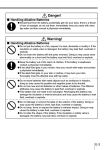
Getting Started with
the Pocket PC Terminal
(Hardware Manual)
Fn
7
8
9
4
5
6
1
2
3
–
CLR
0
User documentation consists of two
manuals:
Pocket PC User’s Guide and Getting
Started with the Pocket PC Terminal.
Be sure to read this Getting Started
Manual first.
Be sure to read the Safety Precautions
contained in this Getting Started Manual
to ensure proper operation of this
product.
Keep this Getting Started Manual in a safe
place for future reference.
P
• Microsoft, Windows, and Windows NT are either registered trademarks or trademarks of
Microsoft Corporation in the United States and/or other countries.
• Pentium is a registered trademark of Intel Corporation.
• CompactFlash is a registered trademark of SanDisk Corporation.
• Datalight is a registered trademark of Datalight, Inc.
• FlashFX™ is a trademark of Datalight, Inc.
Copyright 1993-2000 Datalight, Inc. All rights reserved.
U.S. Patent Office 5,860,082
• All other product and company names mentioned herein may be the trademarks of their
respective owners.
• CAUTION-Battery pack is suitable for use only with Pocket PC Terminal, Model IT-700/70.
• Dispose of used batteries according to the manufacturer’s instructions.
• Information in this manual is subject to change without notice.
• CASIO shall have neither liability nor responsibility to any person or entity with respect
to any loss or damages arising from the information contained in this book.
• Due to the ever changing landscape of the handheld computer field, compatibility of
future products with past or current products cannot be assured and, therefore, compatibility of products shall be solely at CASIO’s discretion.
• This manual does not provide information about programming and downloading. See
other manuals coming with IT-700/70 for information about these subjects.
Safety Precautions
Congratulations upon your selection of this CASIO Product. Be sure to read the
following Safety Precautions before trying to use it for the first time.
Markings and Symbols
The following are the meanings of the markings and symbols used in these Safety
Precautions.
Danger
This symbol indicates information that, if ignored or applied
incorrectly, creates the danger of death or serious personal injury.
Warning
This symbol indicates information that, if ignored or applied
incorrectly, creates the possibility of death or serious personal
injury.
Caution
This symbol indicates information that, if ignored or applied
incorrectly, creates the possibility of personal injury or property
damage.
• A diagonal line indicates something you should not do. The symbol shown
here indicates you should not try to take the unit apart.
• A black circle indicates something you should do. The symbol shown here
indicates you should unplug the unit from the wall outlet.
Precautions During Use
Warning
Disassembly and Modification
• Never try to disassemble or modify the Pocket PC Terminal in any way.
High voltage inside creates the danger of electric shock. There are hot parts
inside the printer. Do not touch these parts with your hands. Doing so can
cause burns.
Abnormal Conditions
• Should the Pocket PC Terminal become hot or start to emit smoke or a
strange odor, immediately turn off the power and contact your original
dealer or an authorized a CASIO service provider. Continued use creates the
danger of fire and electric shock.
1
Warning
Foreign Objects
• Should any foreign matter get into the Pocket PC Terminal, immediately
turn off the power and contact your original dealer or an authorized CASIO
service provider. Continued use creates the danger of fire and electric shock.
Dropping and Damage
• Should you drop the Pocket PC Terminal and damage it, immediately turn
off the power and contact your original dealer or an authorized CASIO
service provider. Continued use creates the danger of fire and electric shock.
Moisture
• Keep the Pocket PC Terminal away from vases, planters, cups, glasses and
other containers of liquid. Also keep it away from metal. Water and metal
getting into the Pocket PC Terminal creates the danger of fire and electric
shock.
Caution
Foreign Objects
• Take care to ensure that metal or combustible objects are not inserted into
the openings of the Pocket PC Terminal. Such objects create the danger of
fire and electric shock.
Location
• Do not locate the Pocket PC Terminal on a surface that is unstable or
uneven. Doing so creates the danger of the Pocket PC Terminal falling,
which can cause personal injury.
• Do not locate the Pocket PC Terminal in an area subject to large amounts of
humidity or dust. Doing so creates the danger of fire and electric shock.
• Do not leave the Pocket PC Terminal for long periods in a car parked in
direct sunlight.
Heavy Objects
• Never place heavy objects on top of the Pocket PC Terminal. Doing so
creates the danger of loss of balance and the object falling, which can cause
personal injury.
2
Caution
LCD Screen
• Never apply strong pressure to the screen or subject it to strong impact.
Doing so can crack the screen or LCD panel glass, which can cause the
danger of personal injury.
• Should the LCD panel glass break, never touch the liquid inside. Doing so
can cause skin inflammation.
– Should liquid from the LCD panel accidentally get into your mouth,
immediately wash your mouth with water and then consult a physician.
– Should liquid from the LCD panel accidentally get into your eyes or onto
your skin, immediately rinse for at least 15 minutes with clean tap water
and then consult a physician.
Optional Lithium-ion Battery Pack
Danger
• Never allow the battery pack to become wet with either fresh water or salt
water. Water can create the danger of battery pack heat emission, explosion,
and fire.
• Never use or leave the battery pack next to open flame, near a stove, or any
other area exposed to high heat. Doing so creates the danger of battery pack
heat emission, explosion, and fire.
• Never use the battery pack with any device other than the Pocket PC
Terminal. Doing so can create the danger of battery pack heat emission,
explosion, and fire.
• Note that the battery pack’s positive (+) and negative (–) terminals must be
oriented correctly when it is loaded into the charger unit or the Pocket PC
Terminal. Connecting the battery pack with its terminals reversed creates the
danger of battery pack fluid leakage, heat emission, explosion, and fire.
• Never dispose of the battery pack by incinerating it or otherwise expose it to
heat. Doing so creates the danger of battery pack heat emission, explosion,
and fire.
• Never allow the positive (+) and negative (–) terminals of the battery pack to
become connected (shorted) by metal. Doing so creates the danger of battery
pack heat emission, explosion, and fire.
• Never transport or store the battery pack together with a necklace, hair pins
or other metal objects. Doing so can short battery pack terminals, creating
the danger of battery pack heat emission, explosion, and fire. Be sure to
place the battery pack in its case whenever transporting or storing it.
• Never throw the battery pack or otherwise subject it to strong impact. Doing
so creates the danger of battery pack heat emission, explosion, and fire.
3
Danger
• Never pierce the battery pack with nails, hit it with a hammer, or step on it.
Doing so can create the danger of battery pack heat emission, explosion, and
fire.
• Never try to take apart the battery pack or modify it in any way. Doing so
creates the danger of battery pack heat emission, explosion, and fire.
• Use only the specified charger unit to charge the battery pack. Use of
another type of charger unit creates the danger of battery pack heat
emission, explosion, and fire.
Warning
• Never place the battery pack in a microwave oven or any other high-voltage
device. Doing so creates the danger of battery pack heat emission,
explosion, and fire.
• Should the battery pack emit a strange odor or heat, change color or shape,
or exhibit any other abnormal behavior, immediately stop using it.
Continued use creates the danger of battery pack heat emission, explosion,
and fire.
• If the battery pack does not achieve full charge after the normal charging
time has passed, stop charging. Continued charging creates the danger of
battery pack heat emission, explosion, and fire.
• Should the battery pack start to leak or emit a strange odor, immediately
move it away from any nearby flame. Leaking battery fluid is combustible,
and exposure to flame creates the danger of explosion and fire.
• Should fluid from the battery pack accidentally get into your eyes, do not
rub them. Immediately rinse your eyes with clean tap water and then consult
a physician immediately.
Caution
• Never use or leave the battery pack in an area exposed to direct sunlight, in a
car parked in direct sunlight, or any other very hot area. Doing so creates the
danger of heat emission and fire, as well as deterioration of battery pack
performance and shortening of its service life.
• Do not use the battery pack in areas where static electricity is being
generated. Doing so creates the danger of battery pack heat emission,
explosion, and fire.
4
Caution
• Should fluid from the battery pack accidentally get onto clothing or your
skin, immediately rinse it off with clean tap water. Prolonged contact with
battery pack fluid can cause skin irritation.
• Keep the battery pack out of the reach of small children. Do not let small
children remove the battery pack from the charger unit or the Pocket PC
Terminal while it is powered on.
Backup Battery Handling
Warning
• Do not charge the battery. Doing so can create the danger of battery leakage,
heat emission, rupture, and fire.
• Do not throw batteries into fire, or heat, take apart or modify them. Doing so
can create the danger of battery leakage, heat emission, rupture, and fire.
• Do not use the battery with its positive(+) and negative(–) terminals
reversed, or store the battery with a necklace, hair pins or other metal object.
Doing so can short the battery and cause excessive current to flow, and can
create the danger of battery leakage, heat emission, rupture, and fire.
• Keep batteries out of the reach of small children. Should small children
swallow a battery, consult a physician immediately.
• If fluid from the battery accidentally get into your eyes, do not rub them.
Immediately rinse your eyes with clean tap water and then consult a
physician immediately.
• If you lick fluid from the battery, immediately rinse with clean tap water,
and consult a physician immediately.
• If the battery starts to leak or emits a strange odor, immediately move it
away from any nearby flame. Leaking battery fluid is combustible.
• When storing and disposing of backup batteries, insulate the terminals with
insulating tape. Mixing batteries together or with other metallic objects
shorts the battery terminal, and can create the danger of battery leakage, heat
emission, rupture, and fire.
5
Caution
• Never throw the battery, subject it to strong impact. Do not allow the battery
to get wet with water. Doing so can create the danger of battery leakage,
heat emission, rupture, and fire.
• Do not leave the battery in locations subject to strong direct sunlight or in
high temperature locations such as in a car. Doing so can create the danger
of battery leakage, heat emission, rupture, and fire.
• Avoid storing the battery on the direct sunlight or in high temperature and
humidity locations. Doing so can create the danger of battery leakage, heat
emission, rupture, and fire, as well as deterioration of battery performance
and shortening of its service life.
• Used batteries may be disposed off as general unburnable rubbish. However,
dispose of used batteries in accordance with any local bylaws and regulations.
AC Power Supply
Warning
• Do not use the Pocket PC Terminal at a voltage other than the specified
voltage. Also, do not connect the Pocket PC Terminal to a multi-plug power
strip. Doing so creates the danger of fire and electric shock.
• Avoid conditions that can cause damage or breaks in the power cord. Do not
place heavy objects on the power cord and keep it away from sources of
heat. Any of these conditions can damage the power cord, creating the
danger of fire and electric shock.
• Never modify, sharply bend, twist, or pull on the power cord. Doing so
creates the danger of fire and electric shock.
• When using the Optical Communication Unit, be sure to use the AC adaptor
(sold separately). Use of another AC adaptor model creates the danger of
fire and electric shock.
• Should the power cord become severely damaged (to the point that wires are
exposed or broken), contact your original dealer or a CASIO service
provider about repair or replacement. Use of a damaged electrical cord
creates the danger of fire and electric shock.
Caution
• Keep the power cord away from stoves and other sources of extreme heat.
Heat can melt the covering of the power cord and create the danger of fire
and electric shock.
6
Caution
• Never pull on the power cord when unplugging it. Doing so can damage the
cord and create the danger of fire and electric shock. (Always hold onto the
plug when unplugging it from the wall outlet.)
• Never touch the plug while your hands are wet. Doing so can create the
danger of electric shock.
• Be sure to unplug the power cord from the wall outlet before moving the
Pocket PC Terminal. Failure to do so can result in damage to the power cord
caused by pulling it, which creates the danger of fire and electric shock.
• Be sure to unplug the power cord from the wall outlet before cleaning the
Pocket PC Terminal.
• Be sure to turn the power OFF and unplug the power cord after use.
• Unplug the power cord from the wall outlet whenever leaving the Pocket PC
Terminal unattended for long periods.
Backup Copies of All Important Data
Caution
• Note that CASIO Computer Co., Ltd. shall not be held liable to you or any
third party for any damages or loss caused by deletion or corruption of data
due to use of the Pocket PC Terminal, malfunction or repair of the Pocket
PC Terminal or its peripherals, or due to batteries going dead.
• The Pocket PC Terminal employs electronic memory to store data, which
means that memory contents can be corrupted or deleted if power is
interrupted due to batteries going dead or incorrect battery replacement
procedures. Data cannot be recovered once it is lost or corrupted. Be sure to
make backup copies of all important data. One way to do this is to use the
separately sold Optical Communication Unit to transfer data to a computer.
Optional Laser Scanner Card
Warning
• Never look directly into the laser beam. Doing so can cause serious eye
damage.
7
Operating Precautions
The Pocket PC Terminal is a precision digital instrument. Incorrect operation and rough
handling can cause data storage problems and other malfunction. Be sure to read the
following precautions to ensure proper operation.
• Charge the battery pack as soon as possible when they start to become weak.
Continued use while power is low can lead to loss of memory data.
• Do not leave dead batteries in the Pocket PC Terminal for long periods. Doing so can
result in battery leakage, which can damage the Pocket PC Terminal and cause
malfunction.
• Use the Pocket PC Terminal under the conditions listed below.
• Temperature: –5°C to 50°C (23°F to 122°F)
• No condensation
Conditions other than those above can cause malfunction.
• Avoid using the Pocket PC Terminal in areas subjected to the following conditions.
• Static electricity
• Extreme heat or cold
• High humidity
• Sudden temperature changes
• Large amounts of dust
• Use only the stylus that comes with the Pocket PC Terminal to press the Reset button.
• Never use a pen, pencil, or other sharp writing implement. Doing so can scratch the
touch screen and cause malfunction.
• Never use thinner, benzene, cosmetics, or other volatile agents to clean the exterior of
the Pocket PC Terminal. Use only a dry soft cloth or a soft cloth moistened with a
weak solution of water and mild neutral detergent.
• Setting the display brightness too high or use of an optionally available
CompactFlash card results in battery life shorter than that indicated in the
specifications of this manual.
8
CASIO ELECTRONICS CO., LTD.
Unit 6, 1000 North Circular Road
London NW2 7JD, U.K.
Please keep all information for future reference.
GUIDELINES LAID DOWN BY FCC RULES FOR USE OF THIS UNIT IN THE U.S.A. (not
applicable to other areas).
NOTICE
This equipment has been tested and found to comply with the limits for a Class B digital device, pursuant
to Part 15 of the FCC Rules. These limits are designed to provide reasonable protection against harmful
interference in a residential installation. This equipment generates, uses and can radiate radio frequency
energy and, if not installed and used in accordance with the instructions, may cause harmful interference
to radio communications. However, there is no guarantee that interference will not occur in a particular
installation. If this equipment does cause harmful interference to radio or television reception, which can
be determined by turning the equipment off and on, the user is encouraged to try to correct the interference
by one or more of the following measures:
• Reorient or relocate the receiving antenna.
• Increase the separation between the equipment and receiver.
• Connect the equipment into an outlet on a circuit different from that to which the receiver is connected.
• Consult the dealer or an experienced radio/TV technician for help.
FCC WARNING
Changes or modifications not expressly approved by the party responsible for compliance could void the
user's authority to operate the equipment.
Proper connectors must be used for connection to host computer and/or peripherals in order to meet FCC
emission limits.
Peripherals and Connectors
Desktop computer
Optical Communication Unit (IT-760IOE)
Lithium ion Battery Pack (DT-5023BAT, DT-5024LBAT)
AC adaptor for Optical Communication Unit (DT-825ADP-U)
CompactFlash Card (CF-16SC-S, CF-64SC-S, CF-256SC-S)
Connectors (DT-883RSC, DT-882RSC, DT-887AX, DT-881RSC, JK-580CA)
Declaration of Conformity
Model Number:
IT-700M30E, IT-760IOE, IT-70M30E
Trade Name:
CASIO
Responsible party: CASIO, INC.
Address:
570 Mt. Plesant Avenue, Dover, New Jersey 07801
Telephone number: 973-361-5400
This device complies with Part 15 of the FCC Rules, Operation is subject to the following two conditions:
(1) This device may not cause harmful interference, and (2) this device must accept any interference
received, including interference that may cause undesired operation.
9
The following details are declared in the 15-country EU Union and 4-country EFTA Union.
Product description / Intended use
EU/EFTA member states intended for use
Member states with restrictive use
Manufacturer
Brand
Type
EU: Austria, Belgium, Denmark, Finland, France,
Germany, Greece, Ireland, Italy, Luxembourg, The
Netherlands, Portugal, Spain, Sweden, United Kingdom
EFTA: Switzerland, Iceland, Lichtenstein, Norway
NONE
CASIO COMPUTER CO., LTD.
CASIO
IT-700M30RC, IT-70M30RC
is tested to and conforms with the essential requirements for protection of health and the safety of the user
and any other person and Electromagnetic Compatibility, as included in following standards:
Standard
EN60950
ETS300 826
and is tested to and conforms with the essential radio test suites so that it effectively uses the frequency
spectrum allocated to terrestrial/space radio communication and orbital resources so to as to avoid harmful
interference, as included in following standards:
Standard
ETS300 328
and therefore complies with the essential requirements and provisions of the Directive 1999/5/EC of the
European Parliament and of the council of March 9, 1999 on Radio equipment and Telecommunications
Terminal Equipment and the mutual recognition of their conformity and with the provisions of Annex IV
(Conformity Assessment procedure referred to in article 10).
The following Notified Bodies have been consulted in the Conformity Assessment procedure:
Notified Body number
0122
Name and address
NMi Certin B.V., PO Box 15, 9822 ZG Niekerk, The Netherlands
The technical documentation as required by the Conformity Assessment procedure is kept at the following
address:
Company
Address, City
Country
Phone number
Fax number
10
CASIO ELECTRONICS CO . LTD.
Unit6, 1000North Circular Road, London NW27JD
United Kingdom
0181-450-9131
0181-452-6323
Change or modifications not expressly approved by the party responsible for
compliance could void the user’s authority to operate the equipment.
Properly shielded and grounded cables and connectors must be used for connection to
host computer and/or peripherals in order to meet FCC emission limits.
AC adaptor with ferrite core must be used for RF interference suppression.
To operate this mobile device in France, there may be National regulatory restrictions to
comply with. For detail please consult “Autorie de Regulation des Telecommunications
(phone no. 01 40 47 71 33)”.
11
Contents
Safety Precautions ............................................................................................ 1
Markings and Symbols ........................................................................................... 1
Precautions During Use .......................................................................................... 1
Optional Lithium-ion Battery Pack ........................................................................ 3
Backup Battery Handling ....................................................................................... 5
AC Power Supply ................................................................................................... 6
Backup Copies of All Important Data .................................................................... 7
Optional Laser Scanner Card .................................................................................. 7
Operating Precautions ...................................................................................... 8
Computer System Requirements .................................................................. 14
System Requirements ........................................................................................... 14
System Diagram .............................................................................................. 16
Option List (Non-U.S. Market Models) ............................................................... 16
IT-700/70 Series Options (U.S. Market Models) .................................................. 17
General Guide .................................................................................................. 18
Setting Up the Pocket PC Terminal ............................................................... 20
Aligning the Touch Screen ................................................................................... 20
Adjusting Screen Contrast .................................................................................... 20
To adjust display contrast using the utilities screen ....................................... 20
To adjust display contrast using the Fn and ten-keys ..................................... 20
Adjusting Screen Brightness (IT-700M30E/M30RC) .......................................... 20
To adjust display brightness using the utilities screen ................................... 20
To adjust display brightness using the Fn and ten-keys ................................. 20
Configuring the Auto Dimmer (IT-700M30E/M30RC) ....................................... 21
Enabling and Disabling the Backlight (IT-70M30E/M30RC) .............................. 21
Using IR Data Communication ....................................................................... 22
Power Requirements ...................................................................................... 23
Replacing the Main Battery .................................................................................. 23
To replace the Standard Battery Pack ............................................................ 24
To replace a Large-capacity Battery Pack ...................................................... 25
Replacing the Backup Battery .............................................................................. 25
Resetting the Pocket PC Terminal ................................................................. 27
When no memory abnormality is discovered ................................................. 27
When a memory abnormality is discovered ................................................... 27
Full Reset (Memory Initialization) .................................................................. 28
Performing a Full Reset ........................................................................................ 28
12
Installing the Hand Strap ................................................................................ 30
IT-700/70 Specifications .................................................................................. 31
Using the Optical Communication Unit (IT-760IOE) ..................................... 33
General Guide ....................................................................................................... 33
Optical Communication Unit Power Requirements ............................................. 35
Using the Optical Communication Unit ............................................................... 35
DIP Switch Settings .............................................................................................. 37
Wall Mounting the Optical Communication Unit ................................................ 38
Daisy Chaining Multiple Optical Communication Units (IT-760IOE) ................ 40
To daisy chain multiple Optical Communication Units ................................. 40
Optical Communication Unit (IT-760IOE) Specifications ................................... 41
Using the Pocket PC Terminal Charger ........................................................ 42
General Guide ....................................................................................................... 42
Charger Unit Power Requirements ....................................................................... 44
Using the Charger Unit ......................................................................................... 44
Wall Mounting the Charger Unit .......................................................................... 45
Pocket PC Terminal Charger (IT-769CHGE) Specifications ............................... 46
Using the Dual Charger .................................................................................. 47
General Guide ....................................................................................................... 47
Using the Dual Charger ........................................................................................ 48
Daisy Chaining Dual Charger Units ..................................................................... 49
Dual Charger (DT-5022CHG) Specifications ....................................................... 50
Using a CompactFlash Card .......................................................................... 51
Loading a Card into Slot 0 .................................................................................... 51
Loading a Card into Slot 1 .................................................................................... 52
Using a Laser Scanner ................................................................................... 54
General Guide ....................................................................................................... 54
Installing the Laser Scanner Card ......................................................................... 55
Reading Bar Codes ............................................................................................... 56
Warning Label ...................................................................................................... 57
Bar Code Scanning Positions ............................................................................... 58
Laser Scanner Card Specifications ....................................................................... 59
Using a Rechargeable Battery Pack .............................................................. 60
Standard Battery Pack Specifications ................................................................... 60
Large-capacity Battery Pack Specifications ......................................................... 60
13
Computer System Requirements
Following are the minimum computer system requirements for installing and using the
applications contained on the bundled Microsoft® CD-ROM.
System Requirements
The minimum desktop PC system requirements for installing and running Microsoft
ActiveSync 3.1 are as follows:
• Microsoft Windows 2000, Microsoft Windows NT Workstation 4.0 with Service
Pack 3 or greater, or Microsoft Windows 95/98.
• Pentium processor for Windows NT or Windows 2000 (166MHz required for
Windows 2000)
-or486/66 DX or higher processor (Pentium P90 recommended) for Windows 95/98.
• 16MB of memory for Windows 95/98 (more memory will improve performance) or
Windows NT (32MB recommended) or Windows 2000 (64MB recommended).
• Hard disk drive with 10 to 50MB of available hard disk space (actual requirements
will vary based on selection of features and your current system configration).
• Available 9 pin communications port, infrared port.
• CD-ROM drive
• VGA graphics card or compatible video graphics adaptor at 256 colors or higher.
• Keyboard
• Microsoft Mouse or compatible pointing device.
Optional components:
• Audio card/speakers for sound.
• Modem and/or Ethernet LAN connection for remote synchronization.
• Microsoft Internet Explorer 4.0 or higher for Mobile Channels or Mobile Favorites
support.
• Additional 153MB of disk space for Microsoft Outlook 2000. 24MB system RAM
recommended. (Microsoft Outlook 2000 is included on the Discovering Microsoft®
Outlook® 2000 CD-ROM.)
14
Important
• Notebook computers equipped with an infrared port and modem may not be
configured so the COM port is the default serial interface. In this case, you need to
change the COM port configuration so the COM port is used as the default serial
interface.
• Even if you are using a desktop PC, check its COM port numbers before installing
Windows® CE Services. For details about how to do this, see the documentation that
comes with your computer.
15
System Diagram
Pocket PC Terminal
IT-700M30E
IT-700M30RC
IT-70M30E
IT-70M30RC
Fn
7
8
9
4
5
6
1
2
3
–
CLR
0
Option List (Non-U.S. Market Models)
Optical Communication Unit
IT-760IOE
Battery Pack
DT-5024LBAT
DT-5023BAT
(Standard Battery Pack) (Large-capacity Battery Pack)
Dual Charger
Optical Communication
Unit AC Adaptor
Dual Charger
AC Adaptor
Pocket PC
Terminal Charger
MPC-577ADP
IT-769CHGE
DT-5022CHG
DT-825ADP-G
DT-825ADP-U
Laser Scanner
DT-5057CBCR
Cables
JK-580CA PC Connection Cable
CompactFlash Storage Card
CF-16SC-S (Flash ROM 16MB)
CF-64SC-S (Flash ROM 64MB)
CF-256SC-S (Flash ROM 256MB)
16
DT-882RSC Satellite Optical Communication Unit-PC Cable
DT-883RSC Satellite Optical Communication Unit-PC Cable
DT-887AX Satellite Optical Communication Unit-PC Cable
DT-881RSC Satellite Optical Communication Unit-Modem Cable
DT-888RSC Satellite Optical Communication Unit Daisy Chain Cable
IT-700/70 Series Options (U.S. Market Models)
Optical Communication Unit
Battery Pack
DT-5023BAT
(Standard Battery Pack)
DT-5024LBAT
(Large-capacity Battery Pack)
Dual Charger
Dual Charger AC Adaptor
Pocket PC Terminal Charger
DT-5022CHG
MPC-577ADP
IT-769CHGE
IT-760IOE
Optical Communication Unit
AC Adaptor
DT-825ADP-U
CompactFlash Card
Cables
CF-16SC-S (Flash ROM 16MB)
CF-64SC-S (Flash ROM 64MB)
CF-256SC-S (Flash ROM 256MB)
JK-580CA PC Connection Cable
DT-882RSC Satellite Optical Communication Unit-PC Cable
DT-883RSC Satellite Optical Communication Unit-PC Cable
DT-887AX Satellite Optical Communication Unit-PC Cable
DT-881RSC Satellite Optical Communication Unit-Modem Cable
DT-888RSC Satellite Optical Communication Unit Daisy Chain Cable
17
General Guide
Left
4
5
6
7
Front
Right
12
18
Back
20
21
3
22
10
26
8
11
Fn
12
13
–
CLR
7
8
9
4
5
6
1
2
3
9
16
24
23
17
0
14 15
19
25
1
Indicator 1
Flashes in accordance with application software configuration.
2
Indicator 2
Flashes or lights to indicate arrival of the alarm time, data
warning, etc.
3
LCD/Touch Screen
Shows characters, operation indicators, etc. Pocket PC Terminal
operations and data input are performed by tapping the Touch
Panel with the provided stylus.
4
Program Key
Turns on power and launches the application program assigned
to the key (initially “Record”).
Important
Carrying the Pocket PC Terminal in briefcase or bag creates the
risk of power being turned on accidentally by this key bumping
against other objects. To protect against this, you can change the
program setup so power is not turned on when this key is
pressed. See the Pocket PC User’s Guide for more information.
5
Action Key
Executes operations, applies settings, and performs other
operations similar to those of the ENTER key on a computer
keyboard.
6
Up Key
Moves highlighting up, scrolls screen contents upwards, and
performs other operations similar to those of the up arrow key
on a computer keyboard.
18
7
Down Key
Moves highlighting down, scrolls screen contents downward,
and performs other operations similar to those of the down
arrow key on a computer keyboard.
8
IR Port
Used as then port for data communication between two Pocket
PC Terminals, between the Pocket PC Terminal and Optical
Communication Unit, etc.
9
Power Key
Turns power on and off*.
* Keep depressed for about one second.
10
Numeric Keypad
Press to input numbers.
11
Fn Key
Used in combination with the 0 to 9 numeric keypad keys to
specify functions assigned by a program.
12
Minus Key
Press to input a minus sign.
13
CLR Key
Cancels key input.
14
Decimal Point Key
Press to input a decimal point.
15
Execute Key
Press to register an input value or to execute the next step of a
program.
16
Microphone
Used for input when using the voice recorder.
17
Speaker
Outputs alarms and other sounds.
18
Headphones Jack
For connection of commercially available earphone or
headphones (ø 3.5mm)
19
Serial Interface
For connection of a serial cable when connecting to a digital
mobile phone, etc.
20
Stylus
Used for Touch Panel input.
21
CompactFlash
Card Slot 0
For insertion of an optional CompactFlash Card
22
Hand Strap Hook
For attachment of the hand strap
23
Battery Pack
Cover Release
Slide to proper position when opening or securing the battery
pack cover.
24
Battery Pack Cover
Covers the battery pack compartment.
25
Backup Battery
Holder
Houses the memory backup lithium battery. You do not need to
remove the hand strap to remove or insert the backup battery
holder.
26
CompactFlash
Card Slot 1
For insertion of an optional CompactFlash Card (IT-700M30E,
IT-70M30E)
19
Setting Up the Pocket PC Terminal
Aligning the Touch Screen
You should align the Touch Screen whenever you feel its response is not what it should
be, or when the wrong function is performed when you tap the Touch Screen.
1. Press the Fn key and then press “4” to display the Touch Screen alignment screen.
• Alternatively, you could tap: [Start] – [Setting] – [System]– [Align Screen].
2. Follow the instructions on the display to align the screen.
Adjusting Screen Contrast
You can use either of the following procedures to adjust display contrast when the color
of the images on the screen appear too light or too dark.
To adjust display contrast using the utilities screen
1. Tap the on-screen [Start].
2. Tap [Settings], [System] tab, [Brightness].
3. Tap the [Contrast] tab.
4. Follow the instructions that appear on the display to adjust contrast.
To adjust display contrast using the Fn and ten-keys
After pressing the Fn key, press “8” to decrease contrast or “9” to increase it.
Adjusting Screen Brightness (IT-700M30E/M30RC)
You can use either of the following procedures to adjust screen brightness for easier
viewing under various lighting conditions.
To adjust display brightness using the utilities screen
1. Tap the on-screen [Start].
2. Tap [Settings], [System] tab, [Brightness].
3. Tap the [Brightness] tab.
4. Follow the instructions that appear on the display to adjust contrast.
To adjust display brightness using the Fn and ten-keys
After pressing the Fn key, press “5” to make the screen darker or “6” to make it lighter.
20
Configuring the Auto Dimmer (IT-700M30E/M30RC)
The auto dimmer helps to conserve battery power by dimming the screen whenever you
do not perform any Pocket PC Terminal operation for a preset amount of time. Use the
following procedure to configure auto dimmer settings.
1. Tap the on-screen [Start].
2. Tap [Settings], [System] tab, [Brightness].
3. Tap the [Auto Dim] tab.
4. Follow the instructions that appear on the display to configure auto dimmer.
Enabling and Disabling the Backlight (IT-70M30E/M30RC)
When the backlight is enabled, the screen of the Pocket PC Terminal illuminates for
easy viewing when you perform an operation where lighting is dim.
• Press [Fn] and then [7] to toggle the backlight between enabled and disabled.
21
Using IR Data Communication
Infrared (IR) data communication can be used to pass data between two Pocket PC
Terminals, etc.
When performing IR data communication, make sure the IR port of the Pocket PC
Terminal and the other unit are directly in line with each other. The IR data
communication range is 0 (direct contact) to 1 meter (25cm for 4Mbps).
Important
• Pocket PC Terminal IR data communication uses a high-sensitivity communication
component.
• To help ensure proper data communication, avoid using cell phones and other devices
that emit radio waves in the vicinity of the Pocket PC Terminal while data
communication is taking place. The cell phone or other device should be at least
30cm from the Pocket PC Terminal.
• When performing FIR (4Mbps) data communication between units, the units should
be 0 to 10 cm or 15 to 25 cm from each other.
22
Power Requirements
The Pocket PC Terminal has a dual power supply, with a main battery to provide power
for normal Pocket PC Terminal operations, and a memory backup battery to provide the
power to retain memory contents.
The main battery is a rechargeable battery pack, which is available in one of two
different types; a Standard Rechargeable Battery Pack (DT-5023BAT) or a Largecapacity Rechargeable Battery Pack (DT-5024LBAT) .
The backup battery is a CR2032 lithium battery.
Battery Terms Used in this Manual
• main battery: main battery that provides power for normal Pocket PC Terminal
operations
• backup battery: CR2032 lithium battery
• standard battery pack: Standard Rechargeable Battery Pack (DT-5023BAT)
• large-capacity battery pack: Large-capacity Rechargeable Battery Pack (DT5024LBAT)
Replace the main battery with a fully charged battery pack at the first sign of lower
power. A battery pack can be charged using the Dual Charger, the Pocket PC Terminal
Charger, or the Optical Communication Unit.
For details the charging procedure, see the documentation that comes with each type of
charger.
Also be sure to replace the backup battery with a new one at the first sign of lower
battery power.
Replacing the Main Battery
Important
• Be sure to keep separate backup copies of all important data!
Removing both the main battery and the backup battery at the same time can cause
data in memory to become corrupted or lost entirely. Data cannot be recovered once
it is corrupted or lost. Make sure you keep separate backup copies of all important
data to protect against its loss.
• The battery pack loses power during testing and during shipment. Make sure you
fully charge the battery pack before using the Pocket PC Terminal for the first time.
• A battery pack gradually loses it ability to recharge over time. If you notice that a
battery pack provides little service after a full charge, it is probably time to replace it.
23
To replace the Standard Battery Pack
1. Make sure that Pocket PC Terminal power is turned off.
If power is on, press the Power key to turn it off.
2. Turn the Pocket PC Terminal over.
3. Slide the battery pack cover release to the [FREE] position, and then remove the
cover.
4. Remove the battery pack as shown in the illustration.
Press here.
5. Taking care that the new battery pack is oriented correctly, load it into the Pocket PC
Terminal.
6. Replace the battery pack cover and then slide the battery pack cover release to the
[LOCK] position.
24
To replace a Large-capacity Battery Pack
You must use the special large-capacity battery pack cover whenever you are using a
large-capacity battery pack to power the Pocket PC Terminal.
For information about removing and installing the large-capacity battery pack cover,
see steps 4 and 6 under “To replace the Standard Battery Pack” above.
Replacing the Backup Battery
The backup battery provides the power required to retain Pocket PC Terminal memory
contents while the main battery is being replaced, and when the main battery goes dead.
Be sure to use only a CR2032 lithium battery as the backup battery.
1. Make sure that Pocket PC Terminal power is turned off.
If power is on, press the Power key to turn it off.
2. Turn the Pocket PC Terminal over.
3. Loosen the screw securing the backup battery holder and remove the holder from the
Pocket PC Terminal.
4. Remove the backup battery from the holder. Wipe the surfaces of a new CR2032
lithium battery with a soft, dry cloth and load it into battery holder with the (+) side
facing downwards (so you can’t see it).
5. Reinstall the backup battery holder and secure it in place with the screw.
25
Warning
Make sure that the plus (+) and minus sides of the backup battery are facing correctly
when you place it onto the backup battery holder.
Caution
Danger of explosion if battery is incorrectly replaced. Replace only with the same or
equivalent type recommended by the manufacturer. Dispose of used batteries according
to the manufacture’s instructions.
26
Resetting the Pocket PC Terminal
The reset operation performs a process that is similar to that performed when you
restart your computer. Any unsaved inputs or edits remaining when you reset the
Pocket PC Terminal are lost, but settings and data stored in memory are retained.
Perform the reset operation whenever you find that the Pocket PC Terminal does not
operate normally due to misoperation or some other abnormality.
To perform a reset operation, use the stylus to press the Reset button on the back of the
Pocket PC Terminal.
When no memory abnormality is discovered
Resetting the Pocket PC Terminal causes the following screens to appear in sequence.
① Start screen
② Today Screen
When a memory abnormality is discovered
Resetting the Pocket PC Terminal causes the following message to appear, without
displaying the start screen.
If this message appears, press Action, which starts the reset procedure. Note, however,
that you may not be able to perform a reset if memory contents are corrupted. In such a
case, you will have to perform a full reset, which is described on the next page.
27
Full Reset (Memory Initialization)
Performing a full reset clears all data stored in Pocket PC Terminal memory (RAM)
and returns all settings to their initial factory defaults. You should perform a full reset in
the following cases.
• When you want to delete all memory (RAM) contents initialize the Pocket PC
Terminal
• If you forget your password and can no longer access the Pocket PC Terminal
• When the Pocket PC Terminal does not operate normally due to a memory
abnormality
• When the message “A problem with memory contents has been found...” appears
Performing a Full Reset
Important
Performing a full reset clears all data stored in Pocket PC Terminal memory (RAM). If
possible, backup Pocket PC Terminal data to your computer or a CompactFlash card
before you perform the full reset.
1. With the Pocket PC Terminal turned on, hold down the Power key and then press as
you hold down the Reset button with the stylus for about one second, until the
message shown below appears.
2. Press the Action key and message shown below appears.
28
3. Press the Action key again.
• This performs the full reset the deletes all memory in Pocket PC Terminal memory
(RAM).
• Pressing the Action key again displays the start screen.
Now perform the required Pocket PC Terminal configuration settings described in the
Read This First.
29
Installing the Hand Strap
The hand strap protects against dropping the Pocket PC Terminal when carrying it
around.
Important
Use the following procedure to install the hand strap on the Pocket PC Terminal.
1. Pass both ends of the hand strap through the hand strap loops on the back of the
Pocket PC Terminal.
2. Fold the two ends of the hand strap back towards each other, and attach the fasteners
as you adjust the length of the strap to fit your hand.
➡
30
IT-700/70 Specifications
Model:
CPU:
Memory:
OS:
Display:
IT-700M30E, IT-700M30RC, IT-70M30E, IT-70M30RC
VR4122
RAM 32MB
Flash ROM 16MB (FlashFX built in)
Microsoft® Windows® CE Version 3.0
IT-700: 240 × 320 dots
IT-700: TFT Color LCD (65,536 colors)
IT-70: 240 × 320 dots
IT-70: FSTN LCD, monochrome with 4 grayscales
Serial Port:
Interface:
Synchronization:
Speed:
IR Port:
Interface:
Synchronization:
Speed:
Card Slot:
CMOS level
Asynchronous only
300 to 115,200bps
IrDA Ver.1.1 Standard
Asynchronous, Frame
4Mbps maximum
CompactFlash Card Type I/Type II (3.3V) × 2 (1 slot for IT700M30RC/IT-70M30RC)
Wireless Communication: IT-700M30RC/IT-70M30RC
Type: Wireless LAN
Modulation: Direct Sequence Spread Spectrum
Radio Frequency: 2400 to 2483.5MHz
Data Rate: 11Mbps maximum
Range: Indoors: 50m; Outdoors: 150m (Actual range depends on
local surroundings.)
Channels: 11 (US, Canada); 13 (ETSI)
Simultaneous Channels: 3
Technical Standard: IEEE 802.11b
Other Functions: Multiple access point roaming
Headphones Jack: ø 3.5mm
Accepts monaural type earphone; stereo type earphones/headphones
Power Requirements:
Main Battery: Standard Rechargeable Battery Pack DT-5023BAT
Large-capacity Rechargeable Battery Pack DT-5024LBAT
Backup Battery: CR2032 lithium battery × 1
Power Consumption: DC 1.5A/3.7 to 5V
31
Approximate Battery Life:
Main Battery: DT-5023BAT 5 hours (IT-700M30E)*; 3.5 hours
(IT-700M30RC)**; 10 hours (IT-70M30E)*, 5 hours
(IT-70M30RC)**
DT-5024LBAT 10 hours (IT-700M30E)*; 7 hours
(IT-700M30RC)**;
20 hours (IT-70M30E)*; 10 hours (IT-70M30RC)**
Backup Battery: Four days when no power is supplied by main battery (When
using the battery that comes with the unit.)
Splash Resistance: IPX2 (when connector covers and all other covers are closed)
Operating Temperature: –5 to 50°C (23 to 122°F)
Dimensions: 85(W) × 165(D) × 27.7(H) mm
Weight: Approximately 330g (IT-700M30E), 320g (IT-70M30E)
Approximately 350g (IT-700M30RC), 330g (IT-70M30RC)
* Repeated sequence with a ratio of 7 parts display and 3 parts calculation; new, fully
charged batteries; normal temperature.
** Repeated sequence with a ratio of 7 parts display and 3 parts calculation and
wireless data communication; new, fully-charged batteries; normal temperature.
32
Using the Optical Communication Unit (IT-760IOE)
The Optical Communication Unit (IT-760IOE) provides a serial interface (RS-232C)
connection between a Pocket PC Terminal and computer for downloading and
uploading system data, files, etc. It can also be used to charge the battery pack loaded
in the Pocket PC Terminal. The Optical Communication Unit comes with a wall mount
unit.
General Guide
Top
2
3
4
1
Front
Back
Right
5
16
13
6
14
15
7
16
12
8 9 10 11
Bundled items
Bottom
Terminal
Support
Terminal Support
Screws
Spacers
Screws
33
1
2
3
4
5
RS-232C Interface
RS-422 Interface (C-IN)
RS-422 Interface (C-OUT)
AC Adaptor Jack
Hook
6
Connection
Detector
Power Contacts
System Operation
Indicator
7
8
9
Communication
Status Indicator
10
Charge Indicator
11
Power Indicator
12
13
14
IR Interface
Power Switch
Base
15
DIP Switches
16
Wall Hook Holes
34
For uploading and downloading system data and files with a computer
For communication between Optical Communication Units
For connection of the AC adaptor
Secures the Pocket PC Terminal in place when on a wallmounted Optical Communication Unit.
Detects whether the Pocket PC Terminal is correctly mounted
onto the Optical Communication Unit.
Supply power to the Pocket PC Terminal.
Indicates the current operational status of the system.
This indicator should light green a short while after you mount
the Pocket PC Terminal onto the Optical Communication Unit.
This system is not operating correctly if the system operation
indicator does not light.
Off:
System problem, or no communication with any of
the Pocket PC Terminals mounted on the Optical
Communication Units
Lit Green: System operating normally, communication being
performed with at least one of the Pocket PC Terminals
mounted on the Optical Communication Units
Indicates the current communication status.
Off:
No communication
Flashing Green: Communication in progress
Lit Red:
Problem with connection between Optical
Communication Units
Indicates the current status of the charger operation for the
lithium ion battery pack load in the Pocket PC Terminal.
Off:
No charging
Lit Red:
Charging
Flashing Red: Battery pack abnormality
Lit Green:
Charging finished
Indicates the power status of the Optical Communication Unit,
and whether a Pocket PC Terminal is mounted.
Off:
Power off
Lit Red:
Power on, Pocket PC Terminal not mounted
Lit Green: Power on, Pocket PC Terminal mounted
For non-contact infrared data communication with a Pocket PC Terminal
Turns power on and off.
Rotate the base 180 degrees (so its high end is facing downwards)
when configuring the Optical Communication Unit for wall mounting.
Use these switches to change the basic configuration of the
Optical Communication Unit.
Wall hooks (spacers + screws) enter these holes for wall mounting.
Optical Communication Unit Power Requirements
Use the AC adaptor that comes with the Optical Communication Unit to power it. Be
sure to connect the AC adaptor to the Optical Communication Unit before starting a
data communication operation with a Pocket PC Terminal. Power is supplied to the
Pocket PC Terminal from the Optical Communication Unit.
Using the Optical Communication Unit
1. Plug the AC adaptor into a wall outlet.
2. After confirming that the Optical
Communication Unit is turned off, plug the AC
adaptor cord into the AC adaptor jack on the top
of the unit.
3. After confirming that both the Optical
Communication Unit and your computer are turned off, use an RS-232C cable (DT881RSC, DT-882RSC, DT-883RSC, DT-887AX) to connect the RS-232C interface
on the top of the Optical Communication Unit (remove the interface cap) to your
computer.
• Leave the interface cap in place if you do not plan to use the RS-232C interface.
4. Turn on the Optical Communication Unit and your computer.
• The power indicator on the Optical Communication Unit should light red at this time.
5. Mount a Pocket PC Terminal onto the Optical
Communication Unit, making sure the IR port on
the side of the terminal is in contact with the IR port
of the Optical Communication Unit. This should
cause the power indicator on the Optical
Communication Unit to turn green and the charge
indicator to light red, indicating that charging has
started.
Charge Indicator
Off:
No charging
Lit Red:
Charging
Flashing Red: Battery pack abnormality
Lit Green:
Charging finished
• The system operation indicator flashes green if system operation is normal and data
communication is being performed (when two or more Optical Communication Units
are connected.)
35
Caution
■ Make sure you charge the battery pack in a location where the
temperature is within the allowable range for charging.
• The allowable range for charging the battery pack is shown below. Charging in
a location where the temperature is outside this range can lower battery pack
performance and service life, and can also lead to leaking and overheating of
the battery pack.
Allowable Temperature for Charging: 0°C to 40°C
Important
• Pocket PC Terminal IR data communication uses a high-sensitivity communication
component.
• To help ensure proper data communication, avoid using cell phones and other devices
that emit radio waves in the vicinity of the Pocket PC Terminal while data
communication is taking place. The cell phone or other device should be at least
30cm from the Pocket PC Terminal.
• If the charge indicator does not light during charging, remove the Pocket PC
Terminal from and then remount it onto the Optical Communication Unit. If the
charge indicator does not light, remove the battery pack from the Pocket PC
Terminal, reload the same battery pack, and try charging again. If the charge
indicator still does not light, it indicates that the battery pack is defective. Replace the
battery pack with a new one.
• Never try to use the Optical Communication Unit to charge a battery other than the
one specifically indicated in this manual.
• A fully charged battery pack naturally discharges little by little, even if you are not
using it. Because of this, the best policy is to wait until just before you need a battery
pack before you charge it.
• For best charging results, keep the contacts of the Optical Communication Unit, the
Pocket PC Terminal, and the battery pack clean by wiping them periodically with a
cotton swab or a dry cloth.
36
DIP Switch Settings
The DIP switches are location on the back of the Optical Communication Unit. You can
control the basic configuration of the Optical Communication Unit by turning the DIP
switches on and off in various combinations.
■ Flow Control
1 2 3 4 5 6 7 8 9 10
None
X ON/X OFF
RS/CS
Special Software
9
OFF
ON
OFF
ON
10
OFF *
OFF
ON
ON
■ Optical Communication Unit –
Host Data Rate
6
7
8
2,400bps
OFF
OFF
OFF
4,800bps
ON
OFF
OFF
9,600bps
OFF
ON
OFF *
19,200bps
ON
ON
OFF
38,400bps
OFF
OFF
ON
57,600bps
ON
OFF
ON
115,200bps
OFF
ON
ON
■ Pocket PC Terminal – Optical
Communication Unit Data Rate
1
2
38,400bps
OFF
ON
115,200bps
ON
OFF *
* Indicates initial default settings.
■ Connection Type
3
4
5
With Host
OFF OFF ON (No daisy chain) *
OFF (Daisy chain)
Daisy Chain
ON OFF
OFF
Intermediate Unit
Daisy Chain
ON OFF
ON
Terminator Unit
Important
Use only the settings shown above. Other settings other than those noted above are for
special maintenance modes.
37
Wall Mounting the Optical Communication Unit
You can use the Wall Mount Unit that comes with the Optical Communication Unit to
configure it for wall mounting.
1. Attach the terminal support to the Optical Communication Unit.
2. Secure the terminal support in place with the two screws.
3. Remove the two screws holding the hook in place. Next, move the hook to the right
side screw holes and secure it in place with the screws.
Left side
Right side (Move hook here for wall-mounting.)
The illustration on the right
shows when the hook on
the Optical Communication
Unit is removed.
4. Remove the two screws (top and bottom) that secure the base of the Optical
Communication Unit.
38
5. Press in on the sides of the base at the four locations indicated by arrows in the
illustration to disengage the base tabs, and then remove the base from the Optical
Communication Unit.
6. Holding the base against the wall where you plan to affix it use a pencil or pen to
mark the locations of each wall hook (spacer + screw). Make sure the high end of the
base is facing downwards when you perform this step.
7. Prepare the wall hooks by sliding a spacer over each of the provided wood screws so
the head of the spacer is on the same end as the head of the screw. Next, drive the
screws into the wall at the two locations you marked in step 5. Make sure the spacer
head is on the same end as the head of the screw. You will not be able to hook the
base unit onto the wall hooks (spacer + screw) if the spacer is backwards.
8. Reattach the base to the Optical Communication Unit, making sure that the high end
of the base is on the same side of the Optical Communication Unit as the terminal
support you installed in steps 1 and 2. Secure the base to the Optical Communication
unit with the two screws (top and bottom).
39
9. Hook the holes of the Optical Communication Unit base onto the wall hooks and
slide the Optical Communication Unit down to secure it.
Important
Be sure to periodically check wall mounted Optical Communication Units for looseness
and tighten the screws whenever necessary.
Daisy Chaining Multiple Optical Communication Units
(IT-760IOE)
You can use optional Daisy Chain Cables (DT-888RSC) to daisy chain up to seven
Optical Communication Units for simultaneous uploading and downloading of data
between a computer and multiple Pocket PC Termnals.
To daisy chain multiple Optical Communication Units
Connect the [C-OUT] terminal of the Optical Communication Unit that is closer to the
host computer to the [C-IN] terminal of the next Optical Communication Unit the
computer in the chain.
• Example: 3-unit daisy chain
To your PC
Caution
Do not connect the [C-OUT] terminal and the [C-IN] terminal to the telephone line.
40
Optical Communication Unit (IT-760IOE) Specifications
Model: IT-760IOE
IR port:
Interface: IrDA Ver.1.0 Standard
Synchronization: Asynchronous
Data Rate: 38,400, 115,200bps
RS-232C:
Synchronization: Asynchronous
Data Rate: 2,400 to 115,200bps
RS-422:
Synchronization: Asynchronous
Data Rate: 9,600 to 115,200bps
Power Supply:
Output: DC5V 1A
Charging
System: Fixed voltage (with voltage control)
Approximate Charge Time: 4 hours (Standard Battery Pack); 8 hours (Largecapacity Battery Pack)
Power Requirements: Special AC Adaptor (DT-825ADP)
Consumption Current: Approximately 900mA
Operating Temperature: 0 to 40°C (32 to 104°F)
Dimensions: 110(W) × 220(D) × 111(H) mm
Weight: Approximately 530g
41
Using the Pocket PC Terminal Charger
You can use the optional Pocket PC Terminal Charger (IT-769CHGE) to charge the
Pocket PC Terminal battery pack. The Pocket PC Terminal Charger comes with a Wall
Mount Unit that you can use to configure the charger for wall mounting.
• The term “Charger Unit” in this section refers to the optional Pocket PC Terminal
Charger (IT-769CHGE).
General Guide
Top
1
Front
Back
Right
2
9
7
3
8
4
9
56
Bundled items
Bottom
Terminal
Support
Terminal Support
Screws
42
Spacers
Screws
1
AC Adaptor Jack
For connection of the AC adaptor
2
Hook
Secures the Pocket PC Terminal in place when on a wallmounted Pocket PC Terminal Charger.
3
Connection Detector Detects whether the Pocket PC Terminal is correctly mounted
onto the Optical Communication Unit.
4
Power Contacts
Supply power to the Pocket PC Terminal.
5
Charge Indicator
Indicates the current status of the charge operation.
Off:
No charging
Lit Red:
Charging
Flashing Red: Battery pack abnormality
Lit Green:
Charging finished
6
Power Indicator
Indicates the power status of the Charger Unit, and whether a
Pocket PC Terminal is mounted.
Off:
Power off
Lit Red:
Power on, Pocket PC Terminal not mounted
Lit Green:
Power on, Pocket PC Terminal mounted
7
Power Switch
Turns power on and off.
8
Base
Rotate the base 180 degrees (so its high end is facing
downwards) when configuring the Optical Communication Unit
for wall mounting.
9
Wall Hook Holes
Wall hooks (spacers + screws) enter these holes for wall
mounting.
43
Charger Unit Power Requirements
Use the AC adaptor that comes with the Charger Unit to power it.
Using the Charger Unit
1. Plug the AC adaptor into a wall outlet.
2. After confirming that the Charger Unit is turned off, plug the AC adaptor cord into
the AC adaptor jack on the top of the Charger Unit.
3. Turn on the Charger Unit.
• The power indicator on the Charger Unit should light red at this time.
4. Mount a Pocket PC Terminal onto the Charger Unit, making sure power contacts on
the bottom of the Pocket PC Terminal is in touch the power contacts of the Charger
Unit.
• The power indicator on the Charger Unit should change from red to green, and its
charge indicator should indicate the current charging status.
44
Charge Indicator
Lit Red:
Charging
Flashing Red:
Battery pack abnormality
Lit Green:
Charging finished
Important
• Make sure you perform charging within the allowable charging temperature range,
which is 0°C to 40°C (32 to 104°F). Charging outside this range can lead to leaking
of the battery pack and overheating. It can also lead to deterioration of battery pack
performance and shortening of the battery pack life.
• If the charge indicator flashes red during a charge operation, remove the Pocket PC
Terminal from the Charger Unit and then remount it. If this does not correct the
problem, it probably means that the battery pack is defective. Replace the battery
pack with a different one.
• Use the Charger Unit to charge only the specified Rechargeable Battery Pack models.
• A battery pack gradually loses its charge, even if it is not used to power a Pocket PC
Terminal. Because of this, you should use a battery pack as soon as possible after you
charge it.
• To ensure proper charging, be sure to occasionally clean the power contacts on the
Pocket PC Terminal and the Charger Unit, and the Rechargeable Battery Pack
terminals by wiping them with cotton swab or a dry cloth.
Wall Mounting the Charger Unit
You can configure the Charger Unit for wall mounting by using the same procedures as
those described for the Optical Communication Unit (IT-760IOE) on page 36.
45
Pocket PC Terminal Charger (IT-769CHGE) Specifications
Power Supply: Output DC5V 1.0A
Charging
System: Fixed voltage (with voltage control)
Approximate Charge Time: 4 hours (Standard Battery Pack); 8 hours (Largecapacity Battery Pack)
Power Requirements: Special AC Adaptor (DT-825ADP)
Consumption Current (Terminal Off): Approximately 800mA
Operating Temperature: 0 to 40°C (32 to 104°F)
Dimensions: 110(W) × 220(D) × 111(H) mm
Weight: Approximately 440g
46
Using the Dual Charger
The optionally available Dual Charger (DT-5022CHG) lets you charge two battery
packs. In this configuration, charging of the second battery pack starts after charging of
the first battery pack is complete.
General Guide
Side
Bottom
Top
3
1
1
4
4
4
4
2
3
3
Bundled items
Attachment
1
Charge Indicator
Indicates the current status of the charge operation.
Off:
No charging
Lit Red:
Charging
Flashing Red: Battery pack abnormality
Lit Green:
Charging finished
2
AC Adaptor Jack
For connection of the AC adaptor
3
For connection to another Dual Charger
Dual Charger
Connection Terminal
4
Connection
Attachment
Screws
Use this attachment to secure two Dual Charger units together.
Important
Each Dual Charger comes with a connection attachment, even though you need only
one connection attachment to secure two Dual Charger units. Keep the extra one on
hand as a spare.
47
Using the Dual Charger
1. Plug the optionally available special AC adaptor into a wall outlet.
2. Plug the AC adaptor cord into the AC adaptor jack of the Dual Charger.
3. Mount a Rechargeable Battery Pack onto the Dual Charger, making sure the battery
pack’s terminals are oriented correctly.
• The charge indicator on the Dual Charger should light red, indicating that charging
has started.
Charge Indicator
Off:
48
No charging
Lit Red:
Charging
Flashing Red:
Battery pack abnormality
Lit Green:
Charging finished
Daisy Chaining Dual Charger Units
You can use the following procedure to daisy chain up to three Dual Charger units and
power them with a single AC adaptor.
1. Remove the connector covers of Dual Charger units as required.
Remove these covers.
2. Connect the connection terminals of the Dual Charger units.
3. Install the connection attachment to the bottoms of the charger units as shown in the
illustration, and secure it in place with the two attachment screws.
49
Dual Charger (DT-5022CHG) Specifications
Model: DT-5022CHG
Charging
System: Fixed voltage (with voltage control)
Approximate Charge Time: 2.5 hours (1 Standard Battery Pack); 5 hours (1
Large-capacity Battery Pack); 5 hours (2 Standard
Battery Packs); 10 hours (2 Large-capacity Battery
Packs)
Power Requirements: Special AC Adaptor (MPC-577ADP)
Consumption Current: Approximately 650mA
Operating Temperature: 0 to 40°C (32 to 104°F)
Dimensions: 110(W) × 100(D) × 49(H) mm
Weight: Approximately 154g
50
Using a CompactFlash Card
The Pocket PC Terminal supports use of the CompactFlash Type I card and Type II card
(3.3V). The following describes how to load and replace a CompactFlash card.
Important
You must remove the Slot 0 card cover when using a laser scanner or another type of
card whose use makes it impossible to close the card cover. In such a case, keep the
card cover in a safe place so you do not lose it. Be sure to close the card cover when
you use the CF storage card.
Loading a Card into Slot 0
1. Wipe the surface of the card, making sure there is no dirt, dust, or oil on it.
2. With the front of the card facing in the same direction as the front of the Pocket PC
Terminal, insert the card into the slot.
You will not be able to insert the card all the way if it is not oriented correctly.
To eject a card from the Pocket PC Terminal, use the stylus or some other pointed
object to press the eject button.
51
Loading a Card into Slot 1
Slot 1 is mainly intended for use as a memory expansion slot. Since you have to remove
the main battery (battery pack) in order to load or remove a card from Slot 1, you should
use it for a card you plan to leave loaded in the Pocket PC Terminal for long periods. Use
Slot 0 for cards that require frequent replacement.
Also not that certain card shapes may be incompatible with Slot 1.
When you load a card into Slot 1, you have to affix a special piece of tape to it to allow
for removal of the card when necessary. You will not be able to remove the card from
Slot 1 if you do not affix the tape.
1. Wipe the surface of the card, making sure there is no dirt, dust, or oil on it.
2. Affix a piece of the special tape that comes with the Pocket PC Terminal to the center
of the card.
3. Slide the battery pack cover release to the [FREE] position, and then remove the
cover.
4. Remove the main battery (battery pack).
5. Remove the Slot 1 cover.
To remove the cover, pull on the
indentation with your finger, and
then raise the cover.
6. With the CompactFlash Card facing upwards, load it into Slot 1.
52
7. Replace the Slot 1 cover.
• Do not push the special tape all the way into the slot. Leave the end sticking out so
you can use it the next time you need to remove the card from the slot.
8. Reload the main battery (battery pack), replace the battery pack cover, and slide the
battery pack cover release back to the [LOCK] position.
When you want to remove the card from Slot 1, pull on the tape you affixed to it.
53
Using a Laser Scanner
Installing an optional Laser Scanner Card (DT-5057CBCR) into the Pocket PC
Terminal provides you with the ability to read various types of bar codes.
General Guide
To the Pocket PC Terminal
Bar Code Reader
Bundled items
Protective Cover
Installation
Screws
(2 silver, 2 black
long, 2 black short)
Screw Covers
Important
• Do not touch the bar code reader with your fingers or allow it to become scratched or
damaged. Dirt or scratches on the bar code reader can cause problems with the read
operation.
54
Installing the Laser Scanner Card
1. Remove the Slot 0 card cover.
With the card cover opened part way, carefully raise it so the cover’s hooks come out
of the holes in the Pocket PC Terminal, and then remove the cover.
2. Insert the Laser Scanner Card into the Pocket PC Terminal.
2
1
3. Use the silver screws to secure the Laser Scanner Card to the Pocket PC Terminal.
4. As shown in the illustration, install the protective cover and secure it in place with
screws.
Long black screws
Short black screws
55
5. Install the screw covers a shown in the illustration.
• To remove the screw covers, insert a flat blade screwdriver at the locations indicated
by arrows in the illustration.
Reading Bar Codes
CASIO provides a library of functions to control the laser scanner.
Software developers can use these functions to incorporate bar code laser scanning into
applications. Contact your CASIO distributor for example bar code scanning software.
56
Important
• If you have a problem reading a bar code, try changing the angle of the label or
Pocket PC Terminal, or the distance between them.
• The laser scanner can read bar codes from a distance of 60 to 420 mm under the
conditions described below.
Required Reading Conditions:
Ambient Illumination: 500 to 900 lux (fluorescent lighting)
PCS: 0.45 to 0.9
Narrowest Bar Thickness: 0.127 to 1.0mm
Warning Label
• This is a warning label for a Class 2 laser device that conforms to IEC60825-1.
• Though there is no danger due to momentary exposure to a Class 2 laser beam, you
should never stare into to the laser for long periods.
• When using the laser scanner, always make sure you carefully follow the procedures
and observe the precautions outlined in this manual. Failure to do so is dangerous.
• The maximum output of the laser beam is less than 1mW. The wavelength is 650mm.
57
Bar Code Scanning Positions
Locate the bar code reader close to the bar code when the bar code is small.
For larger bar codes, move the bar code reader further away so the beam can cover the
entire bar code.
Margin
Margin
Correct
Correct
Wrong
Correct
Wrong
Wrong
Wrong
Warning
• Never allow the laser beam to shine directly into your eyes or the eyes of others.
• Never look directly into the laser beam.
58
Laser Scanner Card Specifications
Model: DT-5057CBCR
Readable Bar Codes: JAN, EAN, UPC, NW-7, CODE39, ITF, CODE93, CODE128,
MSI, IATA, Industrial 2 of 5
Readable Distance: 60 to 420mm (with protective cover installed)
Interface: CompactFlash Card Type II (3.3V)
Consumption Current: Approximately 140mA
Operating Temperature: –5 to 50°C (23 to 122°F)
Dimensions: 52(W) × 60(D) × 12(H) mm
Weight: Approximately 25g
59
Using a Rechargeable Battery Pack
Two types Rechargeable Battery Packs are available. You can select the type you need
to suit the amount of time you need to run the Pocket PC Terminal, and the operating
environment (options, etc.)
When using the Large-capacity Rechargeable Battery Pack, you must change the
battery pack cover to the large-capacity battery pack cover.
Important
Be sure to keep the Rechargeable Battery Pack in its special soft case whenever it is
removed from the Pocket PC Terminal.
Standard Battery Pack Specifications
Model: DT-5023BAT
Rated Capacitance: 1550mAh
Rated Voltage: 3.7V
Dimensions: 37(W) × 57(D) × 13(H) mm
Weight: Approximately 45g
Accessories: Soft Case
Large-capacity Battery Pack Specifications
Model: DT-5024LBAT
Rated Capacitance: 3100mAh
Rated Voltage: 3.7V
Dimensions: 37(W) × 57(D) × 24(H) mm
Weight: Approximately 87g
Accessories: Soft Case
60
CASIO COMPUTER CO., LTD.
6-2, Hon-machi 1-chome
Shibuya-ku, Tokyo 151-8543, Japan
Printed on recycled paper.
PN410346-002
MO0101-003002C Printed in Japan