1
DT-X11 Series
Software Manual
(Version 1.01)
CASIO Computer Co., Ltd.
Copyright ©2006. All rights reserved.
September 2006
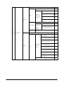
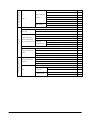
Table of Contents
Chapter
Chapter
1
1.1
1.2
2
2.1
2.2
2.2.1
2.2.2
2.2.3
2.3
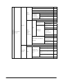
3
3.1
3.1.1
3.1.2
3.1.3
3.1.4
3.1.5
3.1.6
3.1.7
3.1.8
3.2
3.2.1
3.2.2
3.2.3
3.2.4
3.2.5
3.2.6
3.2.7
3.3
3.3.1
3.3.2
3.3.3
3.3.4
3.3.5
3.3.6
3.3.7
3.3.8
3.3.9
3.4
3.4.1
3.4.2
3.4.3
Editorial Record
Preface
Product Overview
Features
Available Options
Applications
System Configuration by Application
Operation by User
Basic Operations
Operation with Multiple Options
Intended Application by Device
Application Development Environment
Functions
Basic Functions
WindowsCE Version 5.0
Displays
Keys
Touch Panel
Audio
Buzzer
Memory Management
LED
Laser Scanner (DT-X11M10E/M10RC)
Basic Specifications
Scanning Method
Scanning Parameters
Scanning Output Format
Scan Result Notification
Expanded Features
Power Control
CMOS Imager (DT-X11M30E/M30U/M30RC)
Basic Functions
Readable Symbologies
Read Assisting Functions
Image Capture Function
Signature Index Functio
Streaming Display Function
LED Intensity
Imager’s APO
Scan Result Notification
USB
Basic Specifications
COM Port
Product ID
2
6
7
8
9
11
12
12
14
14
15
17
20
21
21
21
39
41
49
50
51
52
54
56
56
58
59
61
68
69
73
74
74
74
76
78
78
79
79
80
80
81
81
81
81
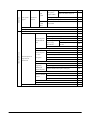
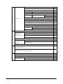
Chapter
3.5
3.5.1
3.5.2
3.6
3.6.1
3.6.2
3.6.3
3.6.4
3.6.5
3.6.6
3.6.7
3.6.8
3.6.9
3.7
3.7.1
3.7.2
3.7.3
3.7.4
3.7.5
3.7.6
3.8
3.8.1
3.8.2
3.8.3
3.8.4
3.8.5
3.8.6
3.8.7
3.8.8
3.9
3.9.1
3.9.2
3.9.3
3.9.4
4
4.1
4.1.1
4.1.2
4.1.3
4.1.4
4.1.5
4.1.6
4.1.7
4.1.8
4.1.9
IrDA
Communication Speeds
COM Port
Bluetooth
Basic Functions
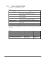
Communication Profiles
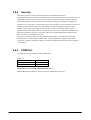
Security
COM Port
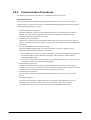
Communication Procedures
Communication Procedures by Profile
Process after Communication Interruption
Processing During Suspend/Resume
Setting SR Mode Parameter
WLAN
Basic Specifications
Expanded Features
Roaming
Zeroconfig
Channels
WLAN Setting with Configuration File
Power Control
Reset Controls
Memory Corruption Check
Low Voltage Monitoring
Power ON Factors
Power OFF Factors
Power Saving
CPU Power State Control
Charging/Supplying the Power
Security
Setting Password for Terminal
Setting Password for Date/Time Properties
Setting Individual ID
Setting Distributor ID
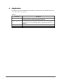
Application
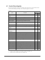
Control Panel Applets
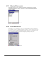
Bluetooth Connection
BuiltInWLanPower
WLAN Settings
CPU Speed
Error Reporting
PC Connection
Remove Programs
Internet Options
Keyboard
3
82
83
83
83
84
84
85
85
86
87
88
88
88
89
89
90
91
92
93
93
98
98
99
100
101
102
103
104
105
106
106
106
106
106
107
108
109
109
110
114
115
116
117
118
123
4.1.10
4.1.11
4.1.12
4.1.13
4.1.14
4.1.15
4.1.16
4.1.17
4.1.18
4.1.19
4.1.20
4.1.21
4.1.22
4.1.23
4.1.24
4.1.25
4.1.26
4.1.27
4.1.28
4.1.29
4.1.30
4.2
4.2.1
4.2.2
4.2.3
4.2.4
4.2.5
4.2.6
4.2.7
4.2.8
4.2.9
4.2.10
4.2.11
4.2.12
4.2.13
4.2.14
4.2.15
4.2.16
4.2.17
4.2.18
4.2.19
4.2.20
4.2.21
4.3
4.3.1
4.3.2
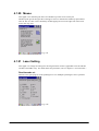
System
Stylus
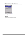
Terminal Server Client Licenses
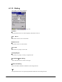
Dialing
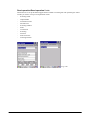
Network and Dial-up Connections
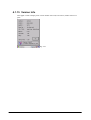
Version Info
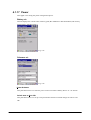
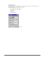
Password
Power
Buzzer
Volume & Sounds
Mouse
Laser Setting
Imager Setting
Display
Storage Manager
Owner
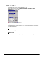
Certificates
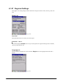
Regional Settings
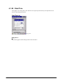
Date/Time
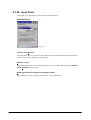
Input Panel
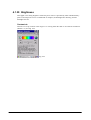
Brightness
Application Programs
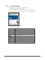
Internet Explorer
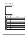
Microsoft WordPad
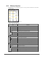
Windows Explorer
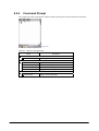
Command Prompt
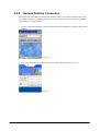
Remote Desktop Connection
Transcriber
Inbox
Calculator
Voice Recorder
Notes
Backup Tool
Laser Scanner Demo
Laser Scanner Read
Image Scanner Demo
Image Scanner Read
Copy Devices
FLCE
ActiveSync
LAN ActiveSync
Terminal
NetSearch
Utilities
Utilities
Auto Setup
4
125
127
128
129
131
134
135
136
138
139
140
140
145
153
155
158
160
161
163
164
165
169
170
172
174
176
177
179
180
182
185
186
188
193
193
194
196
197
200
201
201
202
204
208
208
209
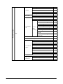
Chapter
4.3.3
4.3.4
4.3.5
4.3.6
4.4
4.4.1
4.4.2
4.4.3
5
5.1
5.2
5.3
5.4
5.5
Auto Recovery Tool
Welcome Wizard
HandWriting
Input Panel (SIP)
Applications
ActiveSync
LMWIN
FCHK
Precautions on Using CMOS Imager
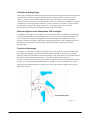
Imaging Performance by Camera’s Optical Operability
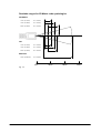
Readable Ranges
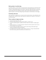
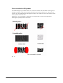
Imaging Performance by Print Quality
Imaging Performance by Settings
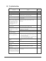
Troubleshooting
210
211
211
211
212
212
212
212
213
214
217
221
224
226
No part of this document may be produced or transmitted in any form or by any means, electronic
or mechanical, for any purpose, without the express written permission of CASIO Computer Co.,
Ltd. in Tokyo Japan. Information in this document is subject to change without advance notice.
CASIO Computer Co., Ltd. makes no representations or warranties with respect to the contents or
use of this manual and specifically disclaims any express or implied warranties of merchantability
or fitness for any particular purpose.
© 2006 CASIO Computer Co., Ltd. All rights reserved.
5
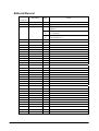
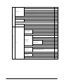
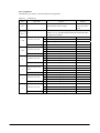
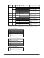
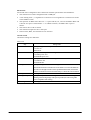
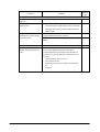
Editorial Record
Manual
Version no.
0.90
1.00
1.01
Date edited
February 2006
April 2006
September 2006
Page
Content
Tentative version
Original version
The content about the AC adaptor is added in Table 1.2 of
Chapter 1.2.
The “ “ notations in Table 3.23 of Chapter 3.2.4 are changed
to “T” notations.
The explanation about “T” notation is added in Table 3.24 to
3.36 of Chapter 3.2.4.
10
61 to
63
63 to
65
6
Preface
This reference manual describes a product overview of the DT-X11 series handheld terminals.
7
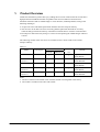
1.
Product Overview
CASIO has extended its product line-up by adding this successor model of DT-X10 series that is
high-performance handheld terminal compatible with various industrial communication
standards and with a built-in CMOS Imager or Laser Scanner (model dependant) aiming at the
following challenges.
• Acquire new users and fulfill replacement demands from the transport industry.
• The successor to the DT-X10 series in meeting fulfill replacement demand for inventory
search/ordering terminals and factory automation terminals that use wireless communication.
• Develop new market that may emerge as a result of incorporating the CMOS Imager and laser
scanner.
The following models of the new series are available to meet various needs in the world’s
transport industry.
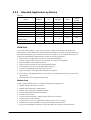
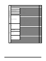
Table 1.1
DT-X11M10E
Laser Scanner
Wireless Communication
Bluetooth IEEE802.11b
Integrated
No
DT-X11M10RC
(see note 1)
DT-X11M30E
Laser Scanner
Integrated
Integrated
No
CMOS Imager
Integrated
No
Integrated
CMOS Imager
Integrated
No
Integrated
CMOS Imager
Integrated
Integrated
No
Model
DT-X11M30U
(see note 2)
DT-X11M30RC
(see note 1)
Scan Engine
PC Card
slot
Integrated
Remark
Equivalent to
DT-X10M10E
Equivalent to
DT-X10M10RC
Equivalent to
DT-X10M30E
Equivalent to
DT-X10M30U
Equivalent to
DT-X10M30RC
Notes:
1. The PC Card slot on the model comes with the WLAN card integrated in the factory.
2. The model is available in the USA and Canada.
8
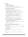
1.1 Features
Incorporates .NET technology
•
•
•
Uses WindowsCE 5.0 Operating System.
Makes effective use of the .NET resources developed by other parties.
Employment of Embedded OS makes it possible to build a flexible WindowsCE system.
Enhanced communicating functions
•
•
•
•
•
Covers GPRS/WLAN, etc. by using various communication cards.
Built in Bluetooth Ver 1.1 module.
The target transfer rate of the WLAN is 5 Mbps, which is the maximum rate of
communication for peer-to-peer connection with PC.
The following protocol stacks are available for Bluetooth interface: GAP (Generic Access),
SDP (Service Discovery), SPS (Serial Port), Dialup Network, File Transfer.
Security function for WLAN
WPA PSK, WPA EAP (EAP-TLS, PEAP-EAP-TLS, PEAP-MS-CHAP-V2, MD5)
Superb scanning capability (for DT-X11M10E/M10RC)
•
•
•
With the integrated laser scanner it is possible to read industrial standard bar code
symbologies.
Scanning performance is compatible with the DT-X10 series handheld terminal.
Multi-step bar code read function.
Superb scanning capability (for DT-X11M30E/M30U/M30RC)
•
•
•
•
With the integrated CMOS imager it is possible to scan 2D code symbologies/1D bar code
symbologies/OCR fonts and to capture images.
Image capturing function (2 to 256 monochromatic tones).
1D bar code symbology scanning performance is compatible with the DT-X10 series handheld
terminal.
Multi-step bar code read function.
Support of outstanding development environment
Ample Microsoft development tools provided for easy application development and an advanced
debug environment.
• Visual Studio 2005
• Visual Studio .NET 2003 (Windows® CE .NET Utilities v 1.1 for Visual Studio .NET 2003)
• eMbedded Visual C++ 4.0
High expandability
The standard PCMCIA slot makes it possible to use various standard peripheral cards.
Font
Simplified Chinese, Traditional Chinese, and Korean fonts as well as English fonts are
preinstalled.
9
Aiming to a full compliance with the “Restriction of the use of certain
Hazardous Substances in electronic equipment (RoHS)” set mandatory
on July 1 2006
The following products have been assembled with devices, components and parts manufactured
using Lead (Pb) free solder.
• DT-X11M10E
• DT-X11M10RC
• DT-X11M30E
• DT-X11M30U
• DT-X11M30RC
10
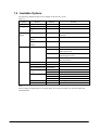
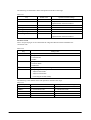
1.2 Available Options
The following dedicated options are available for the DT-X11 series.
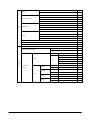
Table 1.2
Option
Cradle
Battery
Battery
charger
AC adaptor
Product
Bridge Satellite Cradle
Battery pack (Standard)
Large-capacity battery
pack
Dual battery charger
Cradle-type battery
charger
Car Mounted Battery
Charger
AC adaptor
Model no.
DT-160IOE
HA-A20BAT
DT-5025LBAT
DT-5022CHG
DT-167CHGE
MPC-577ADP
AD-S45150AU
AD-S42120AE
Car Power Cable
Wall Mount Unit
CF Card Extension Unit
Communication Card
Cover
RS-232C Cable
RS-422 Cable
USB Cable
Maximum 3 units of DT-5022CHG can be
connected.
DT-169CHGE
AD-S45150AE
Others
Remark
DT-827CAC
DT-891WH
DT-894CFU
DT-892TCV
DT-893LTCV
DT-882RSC
DT-883RSC
DT-887AXA
DT-888RSC
DT-380USB
See note.
For DT-5022CHG, input AC110V to 230V,
with US power cord
For DT-5022CHG, input AC110V to 230V,
with Europe power cord
For DT-160IOE/DT-169CHGE, input
AC110V to 230V
For DT-167CHGE
Standard size
Large size
For connection between cradle and PC.
For connection between cradle and PC.
For connection between cradle and PC.
For daisy chain connection.
For connection between cradle and PC.
Note:
The AC adaptor is phased out as of August 2006. The successor models are AD-S45150AE and
AD-S45150AU.
11
2.
Applications
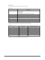
This chapter describes some of the usage scenarios for the DT-X11 series handheld terminal.
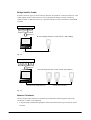
2.1 System Configuration by Application
1.
T
Terminal for automobile drivers
WWAN Card
• Transmits data in real time input at a customer to the center
• Receives/sends instruction e-mails to/from the center.
Car Mounted
Battery Charger
IrDA or Bluetooth
Portable printer
Fig. 2.1
2.
Terminal for warehouse application
WLAN Card
Transmits data in real time input in the
office via WLAN.
Charger
IrDA or Bluetooth
Portable printer
Fig. 2.2
12
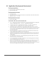
.
3. Terminal in WAN and LAN configuration
WLAN Card
WWAN Card
Transmits data in real time input in the
field through WWAN, and in the office
through WLAN.
Charger
IrDA or Bluetooth
Portable printer
Fig. 2.3
4.
Terminal in conventional configuration
• Temporarily stores input data in this
terminal without using a communication
card, then uploads it to connected PC.
Cradle
IrDA or Bluetooth
Portable printer
Fig. 2.4
13
2.2 Operation by User
Assuming actual operation is performed by the end user, this chapter describes the method of use
and restrictions that apply to the terminal, including the optional devices.
2.2.1
•
•
•
•
•
•
Basic Operations
For operating the touchpanel it is recommended to use the accompanied stylus, since direct
operation with your fingers may cause a malfunction or soil the screen.
The Trigger keys are designed and built so that the terminal can be held by single hand to scan
symbols.
The numeric keys should always be operated by fingers.
When replacing the battery pack, first turn off the terminal power then open the battery
compartment lid to perform battery replacement.
Do not operate the RESET switch on the back of terminal unless the terminal freezes, etc.
There is no guarantee that data currently held will be retained if the RESET switch is pressed
during normal operation.
14
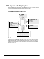
2.2.2
Operation with Multiple Options
Since many built-in devices and externally connected optional devices may co-exist, the user must
observe some precautions and restrictions when using them concurrently.
Optional devices available for the DT-X11
A
-PCMCIAWLAN card
GPRS CARD
B
D
-CF- (Expansion slot)
FROM CARD
WLAN CARD
GPRS CARD
Device recommended by CASIO
-IrDA-
Connecting Bridge Satellite
Cradles
Connecting HTs
Printer
D
C
-Bluetooth-
Printer
Cellular phone, etc.
-Charge terminals-
・Cradle-type battery charger
・Connecting Bridge Satellite Cradles
Fig. 2.5
A, B, C, and D can all be physically connected at the same time, since their connection ports are
different from one another. Devices included in the same boxes A, B, C and D above cannot be
used concurrently. The following describes the conditions that must be observed to use multiple
devices at the same time.
15
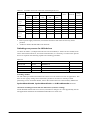
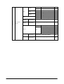
Table 2.1
Possible concurrent connection with multiple devices
PCMCIA
Application
CF (Extension slot)
Charge
IrDA
Bluetooth
-
Yes
Yes
Yes
-
-
Yes
Yes
Yes
Yes
-
Yes
Yes
Yes
-
Yes
Yes
Yes
WLAN
WWAN
FROM
WLAN
WWAN
card
card
card
card
card
Terminal
-
Yes
-
-
used by
-
Yes
Yes
driver
-
Yes
-
Terminal
Yes
-
-
-
used in
terminal
Yes
-
Yes
-
-
Yes
Yes
Yes
warehouse
-
-
-
Yes
-
Yes
Yes
Yes
Terminal
-
-
Yes
-
-
Yes
Yes
Yes
-
-
-
-
-
Yes
Yes
Yes
used for
others
Notes
• Due to power supply restrictions, concurrent connection with some devices may not be
possible.
• “WWAN” denotes World Wide Area Network.
Switching over process for LAN devices
As shown in Table 2.1, multiple LAN devices can be installed (i.e. the drivers are loaded) at one
time in the terminal. However, for actual communication, it is necessary to switch to the specific
device as required. The following explains the switching procedure:
Table 2.2
Device
WLAN card
WLAN card
LAN card
LAN card
Slot
CF slot
PCMCIA slot
CF slot
PCMCIA slot
Feature/Protocol
Remark
IEEE802.11b
IEEE802.11b
LAN connection via 10BASE-T networking
LAN connection via 10BASE-T networking
Switching method
An API will be provided which enables the switch over of LAN devices from an application. This
does not use registry settings and it is therefore possible to switch over instantly without
performing a reset. For further details, refer to the Common Device Control Library Manual for
SysCardDetectDisable , SysCardDetectEnable and CLBCardDetectGet functions.
T
T
T
T
T
T
Automatic switching between WWAN and WLAN (seamless roaming)
If both WWAN and WLAN are to be used, a function to change over is not supported by the OS.
The application should use the method described above to switch over.
16
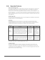
2.2.3
Intended Application by Device
Table 2.3
Device
FROM card
Modem card
LAN card
WLAN card
Printer
Cellular phone
Battery charge on Cradle
Connecting to Bridge
Satellite Cradle
Connecting HTs
PCMCIA
CF
Bluetooth
IrDA
Yes
Yes
Yes
-
Yes
Yes
Yes
-
Yes
Yes
-
Yes
-
Charge
terminal
Yes
-
-
-
Yes
Yes
-
-
Yes
Yes
-
FROM Card
Used as the storage memory. Since it has a memory configuration that does not require any
backup battery, which differs from the RAM disk installed in the terminal, it can store data even
when the terminal battery power has been consumed. In addition, it can easily be removed and
replaced so that handling of data with the CF card can be easily performed.
• Real-time data storage (the access speed is lower than RAM disk.)
• Storage of large-volume data such as master file, etc., that is never updated
• Batch installation (with SETUP function)
• Self-execution on startup by reset (with SETUP function)
• Self-execution at power on (with AUTORUN function)
• Possible to plug/unplug while terminal power is on.
• Stops accessing to secure data when the back lid is opened.
• Power OFF is suspended until the recovery process is completed if the Power key is pressed
during access.
• Improved speed for saving data into the card
Modem Card
Used to enable communication via a modem connected to telephone line.
• Modem card for connection via cable
• Modem Card with built-in fixed antenna
• Modem Card with built-in adjustable antenna
• Real-time upload/download of information
• Send and receive mail
• Call-in function (function to inform the user that mail is received)
• Security function (VPN (PPTP))
• To secure data, access is stopped when the battery pack cover is opened.
• Disables Power OFF if the Power key is pressed during communication.
• Sets up APO (disabled) to default to avoid interruption of in-progress communication.
17
LAN Card
Used to perform communication by connecting to the 10BASE-T Ethernet environment.
• Permanent LAN connection (operating the terminal as desktop unit)
• Independent LAN connection (connecting the LAN cable or LAN card as required)
• Real-time upload/download of information
• Send and receive mail
• Security function (VPN (PPTP))
• To secure data, access is stopped when the battery pack cover is opened.
• The application should implement the function to disable Power OFF when Power key is
pressed during communication.
• Possible to automatically re-establish communication when the terminal is restored through
the resume operation.
• Sets up APO (disabled) to default to avoid interruption of in-progress communication.
Integrated WLAN Card (applicable to DT-X11M10RC and DT-X11M30RC)
Used to communicate in WLAN that is compatible with IEEE802.11b.
• Real-time upload/download of information
• Send and receive mail
• Security function
VPN (PPTP), WEP128/64bit, WPA PSK, WPA EAP (EAP-TLS, PEAP-EAP-TLS,
PEAP-MS-CHAP-V2, MD5)
• To secure data, access is stopped when the battery pack cover is opened.
• The application should implement the function to disable Power OFF when the Power key is
pressed during communication.
• Possible to automatically re-establish communication when the terminal is restored through
the resume operation.
• Sets up APO (disabled) to default to avoid interruption of in-progress communication.
• Transmission rate speed is 5 Mbps.
Printer
It is possible to send print data to any IrDA-compatible printer or Bluetooth-compatible printer.
The Bluetooth serial profile is supported by the terminal.
Cellular Phone
It is possible to dial-up any Bluetooth-compatible cellular phone without using a cable. The
Bluetooth dial-up profile is supported by the terminal.
Cradle-type Battery Charger
This is the Cradle-type Battery Charger on which the terminal is mounted for charging the
installed battery pack. It is possible to install it on a wall (in wall mount configuration) indoor.
18
Bridge Satellite Cradle
It features with two types of serial interface, RS-232C and USB, for connection with a PC. This
cradle supplies power to the terminal as well as charging the battery pack. By connecting
cradle-to-cradle via RS-422 interface it is possible to chain-connect a maximum of 8 handheld
terminals.
Application 1
Data
Data
Data
Database
Between Bridge Satellite Cradle and HT : FIR (4Mbps)
Connection via RS-232C / USB interfaces
Fig. 2.4
Application 2
Data
Data
Data
Database
Between Bridge Satellite Cradle and HT: FIR (4Mbps)
..…
Via RS -232C/USB interfaces
Via RS -422 interface
Fig. 2.5
Between Terminals
The use of HT-to-HT connection is assumed for maintenance and development. HT to HT
connection via cable is not supported.
• Using the IrDA or Bluetooth capabilities, build a child terminal using a terminal as master
terminal.
19
2.3 Application Development Environment
Development platform
•
•
Microsoft Windows 2000 (SP2 or later release)
Microsoft Windows XP
Development environment
•
•
•
Visual Studio 2005
Visual Studio .NET 2003+WindowsCE Utilities for Visual Studio .NET 2003 Add-on Pack 1
eMbedded Visual C++ 4.0 +SP4
T
T
Development environment
•
DT-X11 Export SDK
Visual Studio .NET 2003 and Visual Studio 2005
•
•
•
•
•
•
•
•
VCC++ application development for the DT-X11 using Visual Studio 2005 is not supported.
Always use eMbedded Visual C++ for VCC++ application development.
Compact Framework 2.0 is implemented in the DT-X11. It is upper-compatible with
Compact Framework 1.0 implemented in the CASIO DT-X10 and IT-500.
The functions of the Common Device Control Library which control various individual
devices integrated in the DT-X11 have different name spaces and names from those available
for the previous CASIO handheld terminals. They are not compatible with the ones in the
previous CASIO library.
VB .NET application or C# application developed with Visual Studio .NET 2003, but not
with the CASIO dedicated libraries will run on the DT-X11.
Application developed with any functions of CASIO dedicated library must be rewritten by
replacing the dedicated functions with the appropriate functions from the Common Device
Control Library.
New application for the DT-X11 can be developed using either VB .NET or C# in Visual
Studio .NET 2003 or Visual Studio 2005.
It is recommended that Visual Studio .NET 2003 is used to modify applications developed
for other handheld terminals for the DT-X11.
However, if Visual Studio 2005 is used to make modification, the solution/project of Visual
Studio .NET 2003 is automatically changed by Visual Studio 2005. This may result in
different configuration of the output folder according to the parameter settings for the project
file. Process your application development with care focusing to this change.
20
3.
Functions
This chapter describes about detailed specifications of the functions implemented in the terminal
and the options.
3.1 Basic Functions
3.1.1
WindowsCE Version 5.0
The terminal integrates Microsoft WindowsCE Version 5.0 as its operating system.
Features at a glance
•
•
•
•
•
•
•
Easy-to-use user interface
.NET Compact Framework is supported
High-speed multitask processing
Large capacity memory support
Abundant peripheral equipment
Easy development thanks to open environment
PPC application operation with AYGShell
Note:
Microsoft applications such as PocketWord and PocketExcel are not implemented.
21
Core Modules
Microsoft core modules integrated in the terminal are as follows.
Table 3.1
Core OS Modules
-.NET Compact Framework 1.0
.NET Compact
Framework
--
SQL Server CE 2.0 .NET Data Provider
--
.NET Compact Framework 1.0 Related Matters
Yes
Smart Device Authentication Utility
Yes
.NET Compact Framework 2.0
Applications and Services Development
SQL Server 2000 .NET Data Provider
.NET Compact Framework 2.0
Yes
SQL Server CE 2.0 .NET Data Provider
Yes
String Safe Utility Function
Yes
Complete C runtime
Yes
C library and
Standard Input/Output (STDIO)
Yes
Runtime
Standard Input/Output ASCII (STDIOA)
Yes
Standard Character String Function - ASCII (corestra)
Yes
C++ Runtime Support for Exception Processing and Runtime Type Information
Yes
Exchange Client
Yes
LDAP (Lightweight Directory Access Protocol) Client
Yes
Microsoft Foundation Classes (MFC)
Yes
Pocket Outlook Object Module (POOM) API
SOAP Toolkit
Yes
Client
Yes
Server
--
SQL Server CE 2.0
--
Standard SDK for WindowsCE
Yes
Yes
XML
XML Core Service
XML
MSXML
3.0
and Document
Object Model
(DOM)
XML SAX
Yes
XML Error Character String
Yes
XML
Yes
Query
Language
(XQL)
XML Minimum Passer
Active Template Library (ATL)
Yes
HTTP
XML Style Sheet Language
Transformation (XSLT)
Yes
Yes
Yes
Continue.
22
OBEX Client
Yes
Object Exchange
Applications and Services Development
Protocol (OBEX)
Message Queue
(MSMQ)
Yes
OBEX Server
OBEX File Browser
Yes
OBEX Receive Tray
Yes
Yes
MSMQ ActiveX Wrapper
Yes
SOAP Reliable Message Protocol (SRMP)
Yes
Yes
COM
COM Storage Area
CoCreateGuid Function for OLE32
Yes
Yes
Yes
Component Service
(COM and DCOM)
Component Object
DCOM
Model
COM
Storage
Area
-DCOM Remote Access
---
Minimum COM (OLE
COM Storage Area
unsupported)
CoCreateGuid Function For
OLE32
Voice Interface
Speech API (SAPI) 5.0
---Yes
Applications - End User
ActiveSync
Pocket Outlook Database Sync
--
File Sync
Yes
Receive Tray Sync
Yes
CAB File Installer/Uninstaller
Yes
FLASH Update Sample Application
--
Windows Messenger
--
Game
Freecell
--
Solitaire
--
Terminal Emulator
File Viewer
Yes
Microsoft Excel Viewer
--
Microsoft Image Viewer
--
Microsoft PDF Viewer
--
Microsoft PowerPoint Viewer
--
Microsoft Word Viewer
--
Help
Yes
Continue.
23
Yes
Audio Playback Redirect
--
Applications - End User
Serial and Parallel Port Redirect
Yes
Smart Card Redirect
---
Remote Desktop
Remote Desktop
Printer Redirect
Connection
Protocol (RDP)
User Interface Dialog Box
Yes
Cut/Copy/Paste Clipboard Redirect
Yes
File Storage Area
Redirect
Yes
Filtered File Storage Area
Redirect
Yes
Word Pad
Yes
Receive Tray
Yes
PNP Notification
Yes
Yes
USB Human Input
Device (HID)
USB Host Support
Class Driver
-USB HID Keyboard and Mouse
--
USB HID Keyboard Only
--
USB HID Mouse Only
--
Core OS Services
USB Printer Class Driver
USB Remote NDIS Class Driver
--
USB Memory Location Class Driver
--
Internet Function (IABASE) Support
--
FormatMessage
Yes
API
Kernel Functions
--
FormatMessage API - System Error Message
Yes
Target Control Support (Shell.exe)
Yes
Fiber API
Yes
Message Queue - Point-To-Point
Yes
Memory Map File
Yes
Serial Port Support
Yes
Display Support
Yes
Device Manager
Yes
Continue.
24
Core OS Services
Debug tool
LMemDebug Memory Device Hook
--
Keyboard Test Application
--
Touch Driver Test Application
--
Tool Hint API
Yes
Remote Display Application
--
Small Kernel Test Sample Application
--
Battery Driver
Yes
Parallel Port Support
--
Notification (select
UI Base Notification
Yes
one)
Non-UI Base Notification
--
Notification LED Support
Yes
Power Control (select
Yes
one)
Power Control (full)
Power Control (minimum)
--
FTP Server
Yes
RAS Server/PPTP Server (receive)
--
Simple Network
SNTP Client With DST
Time Protocol
SNTP Server
Yes
--
(SNTP)
SNTP Auto Update and Server Sync
--
Communication Services and Networking
Telnet Server
Yes
Yes
Web Server
(HTTPD)
Web Server Control ISAPI
--
WebDAV Support
--
Active Server Page
Server
(ASP) Support
-JScript 5.6
--
VBScript 5.6
--
Device Control ISAPI Extension
Web Proxy
---
Windows
Peer-To-Peer
Network
Peer Name Resolve Protocol (PNRP)
--
Personal Information Control
--
Core Server Support
Yes
--
File Server
File Server Customizable UI
--
Print Server
--
Guardian Implemented Restrictions
--
Continue.
25
Native Wi-Fi WLAN Access Point Component
--
Network - Local Area
Native Wi-Fi WLAN STA
Yes
Network (LAN)
Wired Local Area Network (802.3, 802.5)
Yes
Wireless LAN (802.11) STA - Auto Configuration and 802.1x
Yes
Bluetooth HID Device
Bluetooth HID - Keyboard
Support
Bluetooth HID - Mouse
--
Bluetooth DUN - Gateway
--
Bluetooth HS/HF and Audio
Bluetooth Profile
Gateway Service
Support
Bluetooth LAP and
Communication Services and Networking
Configuration Utility
Bluetooth PAN
Bluetooth Stack With
Network - Personal
Bluetooth
Universal Writable Driver
Area Network (PAN)
Bluetooth Protocol
Driver
Stack With Transport
Bluetooth Stack With
Driver Support
Integrated SDIO Driver
Bluetooth Stack With
Integrated UART Driver
Bluetooth Stack With
Integrated USB Driver
IrDA
----
--
---Yes
Telephony API
Yes
(TAPI 2.0)
Network (WAN)
--
Bluetooth Stack With
Integrated CSR Chip Set
Network - Wide Area
--
Unimodem Support
Yes
Ethernet Point-To-Point Protocol (PPPoE)
Yes
Yes
Dial Up Network
Standard Modem Support for Dial Up Network
Yes
Auto Dial
Yes
Virtual Private
L2TP/IPSec
Yes
Network
PPTP
Yes
(RAS/PPP)
Continue.
26
IPSec v4
Yes
NDIS Packet Capture DLL
Yes
NDIS User Mode I/O Driver
Yes
Yes
TCP/IP
IP Help API
Yes
TCP/IPv6 Support
Yes
Communication Services and Networking
USB Flash Configuration Tool
--
Windows Network API/Redirect (SMB/CIFS)
Yes
Winsock Support
Yes
Internet
Yes
Connection Share
Gateway Log
(ICS)
--
Gateway User Interface Reference
Network Functions
--
Domain Search
Yes
Network Driver Configuration (NDIS)
Yes
Network Bridge Function
Yes
Network Utility (IpConfig, Ping, Route)
Yes
Firewall
-UPnP Audio -Video
DCP
AV Control Point API
--
AV Device (API)
--
AV Renderer Sample
--
Universal Plug and
UPnP Tool
--
Play (UPnP)
Control Point API
--
Sample UPnP IGD Schemer Mounting
--
Device Host API
--
Device Host API (minimum subset)
Remote Configuration Framework
Expansion DNS
--Yes
Query and Update
(DNSAPI)
Security Protected DDNS
Expandable Authentication Protocol
Continue.
27
-Yes
File Systems and Data Store
System Password
Yes
Database Support
Yes
File system - Internal (select
File System Applicable for RAM and ROM
one)
File System Only Applicable for ROM
--
Duplication of File and
Count Base
--
Database (select one)
Bit Base
Yes
Registry Storage Area (select
Hive Base Registry
Yes
one)
RAM Base Registry
--
Compression
Yes
Yes
Storage Area Manager
Arial
Comic Sans MS
CD/UDFS File System
--
EDB Database Engine
Yes
FAT File System
Yes
Transaction Safe FAT File System (TFAT)
--
Binary ROM Image File System
--
Partition Driver
Yes
Storage Area Manager Control Panel Applet
Yes
Arial (Subset 1_30)
--
Arial Black
--
Arial Bold
--
Arial Bold Italic
--
Arial Italic
--
Comic Sans MS
--
Comic Sans MS Bold
--
Courier New (Subset 1_30)
Fonts
Yes
Courier New
Georgia
Yes
Courier New Bold
--
Courier New Bold Italic
--
Courier New Italic
--
Georgia
--
Georgia Bold
--
Georgia Bold Italic
--
Georgia Italic
--
Impact
--
Kino
--
MSLogo
--
Continue.
28
Tahoma (Subset 1_07)
Tahoma
Yes
Tahoma Bold
--
Times New Roman (Subset 1_30)
Fonts
Times New Roman
Trebuchet MS
Verdana
Yes
Times New Roman Bold
--
Times New Roman Bold Italic
--
Times New Roman Italic
--
Trebuchet MS
--
Trebuchet MS Bold
--
Trebuchet MS Bold Italic
--
Trebuchet MS Italic
--
Verdana
--
Verdana Bold
--
Verdana Bold Italic
--
Verdana Italic
--
Webdings
--
Wingding
Yes
Symbol
Yes
Unicode Script Processor Supporting Complex Scripts
-English (American) Only Support for Languages
Local Service (select one)
Support for Languages (NLS)
Keyboard
International
Arabic
Local Specific
Font
Kanarese
Support
Gujarati
India
Tamil
Telugu
Continue.
29
-Yes
Arabic Keyboard (101)
--
Arial (Subset 1_08)
--
Arial Bold (Subset 1_08)
--
Courier New (Subset 1_08)
--
Tahoma (Subset 1_08)
--
Tahoma Bold (Subset 1_08)
--
Keyboard
Kanarese Keyboard
--
Font
Tunga
--
Keyboard
Gujarati Keyboard
--
Font
Shruti
--
Keyboard
Tamil Keyboard
--
Font
Latha
--
Keyboard
Telugu Keyboard
--
Font
Gautami
--
Punjabi
India
Hindi
Marathi
International
Thai
Local Specific
Support
German
Input System
French
Input System
Keyboard
Punjabi Keyboard
--
Font
Raavi
--
Keyboard
Hindi Traditional Keyboard
--
Font
Mangal
--
Keyboard
Marathi Keyboard
--
Font
Mangal
--
Keyboard
Thai Kedmanee Keyboard
--
Font
Tahoma (Subset 1_08)
--
Transcriber Handwriting Recognition
Application
Transcriber Handwriting Recognition
Application
Keyboard
Hebrew
English
(Global)
English
(American)
Font
Input System
Input System
Continue.
30
--
Hebrew Keyboard
--
Arial (Subset 1_08)
--
Arial Bold (Subset 1_08)
--
Courier New (Subset 1_08)
--
Tahoma (Subset 1_08)
--
Tahoma Bold (Subset 1_08)
--
Handwriting Recognition Engine (HWX)
Transcriber Handwriting Recognition
Application
--
Yes
Yes
Agfa AC3 Font Compression
--
GB18030 Data Conversion
--
SC_Song
-SimSun and NSimSun
SimSun and NSimSun (Subset
2_20)
SimSun and NSimSun (Subset
SimSun
Font
and
NSimSun
(select one)
2_50)
SimSun and NSimSun (Subset
2_60)
SimSun and NSimSun (Subset
2_70)
SimSun and NSimSun (Subset
2_80)
International
SimSun and NSimSun (Subset
Local Specific
Simplified
Support
Chinese
2_90)
Pocket
IME
---Yes
-----
Double Spell Software
Keyboard - Small
---
1.1MB Minimum
MSPY 3.0
Input System
Editor (select
MSPY 3.0
one)
for
Windows
CE
Database for
WindowsCE
(select one)
--
Database
1.3MB Compact
--
Database
1.7MB Standard
--
Database
Double Spell (Shuang Pin)
Software Keyboard - Large
Double Spell (Shuang Pin)
Software Keyboard - Small
Continue.
31
---
Agfa AC3 font compression
--
Gulim (GL_CE)
Gulim and GulimChe (Subset
1_30)
Font
Gulim and
GulimChe
(select one)
Korean
Gulim and GulimChe (Subset
1_40)
Gulim and GulimChe (Subset
1_50)
Gulim and GulimChe (Subset
1_60)
Input System
--Yes
---
Korean Software Keyboard Sample
--
Handwriting
--
Recognition
Engine
MboxKOR HWX Sample UI
--
(HWX)
International
Input System
Editor
Local Specific
IME 97
--
Agfa AC3 Font Compression
Support
-MS Gothic, MS P Gothic and
MS UI Gothic
MS Gothic, MS P Gothic and
MS UI Gothic (Subset 1_50)
MS Gothic, MS P Gothic and
MS UI Gothic (Subset 1_60)
MS Gothic
Japanese
Font
(select
one)
MS Gothic, MS P Gothic and
MS UI Gothic (Subset 1_70)
MS Gothic, MS P Gothic and
MS UI Gothic (Subset 1_80)
MS Gothic, MS P Gothic and
MS UI Gothic (Subset 1_90)
MS Gothic and MS P Gothic
(Subset 30)
MS Gothic and MS P Gothic
(Subset 30_1_19)
MS Mincho and MS P Mincho
Continue.
32
--
T
T
---------
Kana Keyboard
--
View of All Characters
--
T
Alphanumeric/English Software Keyboard
--
T
Stroke Count Search
Input
System
Handwriting
Recognition
Engine (HWX)
T
T
--
T
T
--
T
Multibox HWX Sample UI
T
--
T
Character Auto Complete - HWX
T
--
T
Sample UI
Radical Search
T
---
IME 3.1 Database
Compact Database
--
(select one)
Standard Database
--
System Tray Icon
Japanese
IME
International
3.1
Input
Local Specific
System
Support
Editor
--
Manager
Property Dialog Box
Optional UI
[Detail Settings]
Component
Dialog Box
--
--
(transverse mode
only)
(select one)
Dictionary Tool
---
T
Pocket IME (select additional
database)
Personal-Local
Name Dictionary
Appended
Dictionary
Test IME
MingLiU and PMingLiU (Subset
Font
MingLiU and
2_70)
PMingLiU (select
MingLiU and PMingLiU (Subset
one)
2_80)
MingLiU and PMingLiU (Subset
2_90)
MS Ming
Continue.
33
T
--
T
TTT
-MingLiU and PMingLiU
Chinese
--
T
--
Agfa AC3 Font Compression
Traditional
T
--Yes
---
Handwriting
Recognition
International
Input
Local Specific
Traditional
Support
Chinese
Engine (HWX)
System
-MboxCHT HWX Sample UI
--
Phonogramic Input (Bopomofo)
--
Radical Input (Chang Jei)
--
Pocket IME
--
Input
System
Editor
Input System Manager (IMM)
Yes
Multilingual User Interface (MUI)
--
Pocket Internet Explorer HTML View (WEBVIEW)
Yes
Yes
Internet Explorer HTML Application
Yes
Internet Explorer
Internet Explorer Theme Library
Yes
HTML/DHTML
Internet Explorer
Yes
API
Plug In Image
Internet Explorer PNG Image
Decoder API
Decoder
Filter and Translation
Internet Explorer RPC Support
Yes
Yes
Yes
Internet Client Services
Yes
Internet Explorer 6.0
Component for
WindowsCE
Internet Explorer
Customizable Font Range
Yes
TV Style
Fixed Width Layout
Yes
Navigation
Disable Vertical Scroll Bar and Event
Yes
Direction Tab
Yes
Internet Explorer Browser Control Host
Yes
Basic API
Yes
Supporting
Multilingual
Internet Explorer
Full API Support for Multilingual Internet Explorer
Yes
Character Set/Encode of Options in Registry
Yes
URL Moniker Service
Windows Internet
Service
XML MIME Viewer
XML Data Island
Control Panel’s [Internet Option]
Yes
Yes
P3P (Platform for Privacy Preferences)
Yes
Passport SSI 1.4 Authentication
Yes
--Yes
Continue.
34
Yes
Internet Client Services
JScript 5.6
Script Encode (Jscript)
Script Authoring (Jscript)
Script
MagBox and InputBox Support
Yes
Script Encode (VBScript)
Yes
Script Authoring (VBScript)
Yes
Pocket Internet Explorer
-Yes
Internet Explorer 6.0
for WindowsCE -
Internet Explorer 6.0 Sample Browser
Yes
Standard Component
TV Style Navigation Component
Yes
Waveform Audio
Audio
Yes
--
Audio Compression
Manager
GSM 6.10 Codec
--
MSFilter Codec
--
Alphablend API (GDI Version)
--
Direct3D Mobile
--
Multimedia Technologies
DirectDraw
Yes
V1 Font Compatibility
--
Static Image Codec Support (Encode and Decode)
Graphics
Yes
Yes
VBScript 5.6
Browser Application
Yes
Yes
BMP Encoder
Yes
Static Image
GIF Encoder
Yes
Encoder
JPG Encoder
Yes
PNG Encoder
Yes
BMP Decoder
Yes
GIF Decoder
Yes
ICO Decoder
--
JPG Decoder
Yes
PNG Decoder
Yes
Imaging
Static Image
Decoder
Gradation Support
Yes
Rasta Font Support
--
Multiple Monitors Support
--
Continue.
35
DirectShow
ACM Wrapper Filter
--
DirectShow Error Message
--
DirectShow Core
DVD - Video
Yes
DirectShow Display
--
DMO Wrapper Filter
--
DVD - Video
--
DVD - Video Sample
--
Windows Media Player
--
Windows Media Player OCX
---
Windows Media
Multimedia Technologies
Player
ASX v1 and M3U File Support
--
ASX v2 File Support
--
ASX v3 File Support
--
Windows
HTTP Windows Media Streaming
--
Media
MMS Windows Media Streaming
--
Technology
NSC File Support
--
Windows Media Multi Cast and Multi
Bit Rate
Media
Windows Media Streaming From Local
Storage Area
---
WMA and MP3 Streaming
--
WMA and MP3 Local Playback
--
G.711 Audio Codec
--
GSM.6.10 Audio Codec
--
IMA ADPCM Audio Codec
--
MP3 Codec
--
Audio Codec and
MPEG-1 layer 1 and 2 Audio Codec
--
Renderer
MS ADPCM Audio Codec
--
Wave/AIIF/au/snd File Parser
Yes
Waveform Audio Renderer
Yes
WMA Codec
--
WMA Voice Codec
--
Streaming Media Playback
Digital Copyright
Management
Continue.
36
--
Digital Rights Management (DRM)
--
DRM License Acquisition OCX
--
Portable Device DRM
--
Multimedia Technologies
Media
DirectShow Video Renderer
--
MPEG-1 Video Codec
--
Video Codec and
MS RLE Video Codec
--
Renderer
WMV/MPEG-4 Video Codec
--
Overlay Mixer
--
Media Format
Video/Image Compression Manager
--
AVI Filter
--
MPEG-1 Passer/Splitter
--
Microsoft Certificate Registration Tool Sample
Yes
Local Authentication
Yes
Subsystem
Password Local Authentication Plug in
Yes
Yes
Security
Powerful Encrypting
Provider’s Encrypting
Service (CryptoAPI 1.0)
Diffie-Hellman/DSS Provider
Smart Card Encryption Provider
Yes
-Yes
Certificate
(CryptoAPI 2.0)
Personal Information Exchange Standard (PKCS #12)
Yes
Encryption Messaging (PKCS #7)
Yes
Capability Information Manager
Yes
Shell and User Interface
Yes
Authentication Service
Kerberos
Yes
(SSPI)
NTLM
Yes
Schannel (SSL/TLS)
Yes
Minimum GDI Configuration
Yes
Graphics, Windowing
Minimum GWES Configuration
Yes
and Event
Minimum Window Manager Configuration
Yes
Shell
Minimum Input Configuration
Yes
AYGShell API Set
Yes
Graphic Shell
Windows Thin Client Shell
(select one)
Standard Shell
Command Shell
Continue.
37
-Yes
Command Processor
Yes
Console Window
Yes
Quarter VGA Resource Longitudinal Mode
Yes
Overlap Menu
--
Controls Option B
Customizable UI
-Sample Skin Resembling Windows XP screen
-Shell and User Interface
Control Panel Applet
User interface
-Yes
Software Input
Software Base Input Panel
SIP for Small Screen
Panel
(SIP) (select one or more)
SIP for Big Screen
Yes
--
Software Base Input Panel Driver
Yes
Touch Screen (stylus)
Yes
Network User Interface
Yes
Mouse
--
Menu Hint
Yes
User Aid
-Animation Control
Shared Control
Shared Control
Shared Dialog Support
PC Authentication
-Yes
Yes
---
Voip Service
VoIP Application
Interface Layer (VAIL)
VAIL Database Store
--
Reference Media Manager
---
Real Time
--
Client API
Device Manager
--
Telephony User Interface
Communication (RTC)
WCE Error Report
Phone Provisioner
SIREN/G.722.1 Codec
--
Phone IME
--
Device Management Client
--
Simple Network Management Protocol (SNMP)
--
Error Report Control Panel
Yes
Error Report Formation Program
Yes
Error Report Transfer Driver
Yes
Report Upload Client
-Report Upload Client User Interface
38
--
3.1.2
Displays
Basic Specifications
The QVGA (320 x 240 dots) mode is supported for the terminal.
Table 3.2
Display specification
X direction
Display size
Y direction
65,536 colors 2-way TFT (16 bpp, Red: 5 bits, Green: 6 bits, Blue: 5 bits)
240 dots
320 dots
Contrast
• Can be set in the range of 1 to 9 (Default = 5).
• Can be set in application with ExtEscape()API function.
• Setup values can be modified in the Brightness properties.
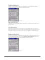
Backlight brightness
A brightness of the backlight can be changed in the Control Panel.
• Setting can be made in one of nine grades for power source either when the power is provided
by an external power supply (by the dedicated AC adaptor via cradle) or when the power is
provided by the installed lithium-ion battery pack.
• Setting can be made in application by using ExtEscape()API function.
• If the brightness is set to 1 (minimum), the backlight is turned OFF.
• The default is 9 (maximum) when an external power source is used or 7 when lithium-ion
battery pack is used.
Backlight Auto Dimmer (Only effect when the terminal is powered by battery pack.)
The Control Panel can be used to set up whether or not the auto dimming function is used and the
waiting time until when dimming begins. Auto dimming is effect only when the power is provided
by the lithium-ion battery pack. It will not function when an external power supply is used.
•
If the terminal is left over in idle state - absolutely no key input or touching on the touch panel
- while the power is turned on, the backlight will be automatically dimmed to save the power
after a given period of time has been elapsed.
• When the terminal is in the auto dimmed state, a press of key or a touching on the touch panel
will disable the auto dimming function to resume the brightness.
• While the auto dimming function has been set enabled, brightness can be set in one of eight
grades. The default is 3.
During the auto dimming function being set enabled, brightness cannot be set any brighter than
the brightness illuminated by the backlight. The defaults are “Enable the auto dimming function”
and “1 minute” for waiting time period until when the auto dimming function activates.
39
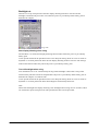
Auto Backlight OFF (in both cases powered by battery pack and via Cradle/Battery
charger)
The Control Panel can be used to set up whether or not the auto backlight off function is used and
the waiting time until when the auto backlight off function activates. The auto backlight off
function is effect for both when the power is provided by an external power source and when it is
provided by lithium-ion battery pack.
•
•
•
If the terminal is left over in idle state - absolutely no key or touch panel inputting - with the
power being turned on, the backlight will be automatically turned off to save energy.
When the terminal is in the auto backlight off state, a press of key or a touching on the touch
panel will disable the auto backlight off function to resume the brightness.
While the power is being provided by lithium-ion battery pack and both the auto dimming
function and the auto backlight off function have been set enabled, either one of the functions
with preset time period shorter than the other will have the priority. The default is “Enable the
auto backlight off function” and “5 minutes for the waiting time” until when the auto backlight
off function activates.
Backlight brightness control by thermal sensor (in both cases powered by battery pack and
via Cradle/Battery charger)
When the thermal censer detects high temperature of the terminal, brightness of Backlight will be
restricted automatically.
• There are two kinds of restrictions. The first one is to restrict steps of brightness control (9
steps) to up to 8 steps. The second one is to restrict steps of brightness control up to 6 steps.
• If the brightness of normal condition or dimmed brightness set by Automatic Backlight
Dimmer (only battery operation) is set greater than brightness which is beyond the range of
the restricted steps, brightness will be restricted automatically to the inside of the restricted
range. However, when the temperature drops and restriction is released, brightness will
recover to the normal setting level automatically.
• It is possible to confirm if the restriction is effective or not by checking the following registry.
[ HKEY_LOCAL_MACHINE\Drivers\Display\CM7200F1 ]
DispSensorLevel : DWORD (0: Normal, 1, 2)
Rotating Display
The rotate display function for rotating the screen at 180 degree is supported. When the screen is
rotated, the touch panel coordinates system rotates in unison.
•
•
The Common Device Control Library can be used to set up this display rotation feature in
application.
ChangeDisplaySettingEx() API function can be used to set up this display rotation feature
in application.
See Microsoft Help for details about ExtEscape() and ChangeDisplaySettingEx() API
functions.
40
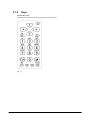
3.1.3
Keys
Keyboard Layout
The following is the keyboard layout employed in the DT-X11.
Fig. 3.1
41
Key Assignments
The following are the key codes and functions assignments.
Table 3.3
Control keys
KEY
Input mode
Operation
Remarks
Fn mode is released
Fn/□
----
Specialized key operation (toggle)
when a key input is
made.
Programm
able (○)
CLR
Returns the VK code set in the registry (Default: VK_F25).
ProgKeyCode : DWORD
Character input mode
Function mode
ENT
[HKEY_LOCAL_MACHINE\HARDWARE\DEVICEMAP\KEYBD]
----
Character input mode
Function mode
1
Deletes 1 character..
A
Perform as “!@#$%~&*()”
a
Perform as “_~`+=|\:;”“
F
Perform as “ESC operation”.
1
Perform as “Enter key”.
A
Perform as “Enter key”.
a
Perform as “Enter key”.
F
1
↑
Character input mode
Function mode
During character input
←
mode
Function mode
→
Character input mode
During Function mode
↓
Character input mode
Function mode
No effect.
Perform as “Cursor up key”.
A
Perform as “Cursor up key”.
a
Perform as “Cursor up key”.
F
Perform as “Cursor up key”.
1
Perform as “Cursor left key”.
A
Perform as “Cursor left key”.
a
Perform as “Cursor left key”.
F
Perform as “Cursor left key”.
1
Perform as “Cursor right key”.
A
Perform as “Cursor right key”.
a
Perform as “Cursor right key”.
F
Perform as “Cursor right key”.
1
Perform as “Cursor down key”.
A
Perform as “Cursor down key”.
a
Perform as “Cursor down key”.
F
Perform as “Cursor down key”.
42
Table 3.4
Function key
KEY
Input mode
Character input mode
F1/BS
Operation
Remarks
Deletes 1 character to left.
Initiate application registered in the registry below.
Function mode
[HKEY_LOCAL_MACHINE\Software\Microsoft\Shell\Keys\40C1]
Character input mode
Perform as “Hyphen”.
Default:sz (path of the application to be initiated)
F2/-
Initiate application registered in the registry below.
Function mode
[HKEY_LOCAL_MACHINE\Software\Microsoft\Shell\Keys\40C2]
Default:sz (path of the application to be initiated)
Character input mode
F3/.
Perform as “Period”.
Initiate application registered in the registry below.
Function mode
[HKEY_LOCAL_MACHINE\Software\Microsoft\Shell\Keys\40C3]
Default:sz (path of the application to be initiated)
Character input mode
F4/Alpha
Input mode switchover
Numeric → Alphabet (U)→ Alphabet (L)
Initiate application registered in the registry below.
Function mode
[HKEY_LOCAL_MACHINE\Software\Microsoft\Shell\Keys\40C4]
Default:sz (path of the application to be initiated)
Table 3.5
Trigger key
KEY
Input mode
Operation
Remarks
Starts reading symbols.
T1/T2
----
Can be set so that the user is informed of the fact the key is pressed.
Turns ON the power if the key is pressed longer than the specified
period of time when the power is OFF.
Setting turning ON the power with key
The Power key and Trigger keys can be assigned to turn on the power (turning on the power and
then invoking application software). Application and function can be freely assigned to other keys
on the keyboard.
Setting the prohibition on turning on the power with key
The function to turn on the power with Trigger keys after the power has been turned off can be
disabled. Using the Common Device Control Library, turning on the power with Trigger keys can
be set enabled or disabled. The default setting is “Disable turning on the power”.
43
Table 3.6
KEY
0
Ten key
Input mode
Character input mode
Character input mode
Function mode
2
3
5
Perform as “‘<,>?/{[]}”.
F
Display or not display SIP.
1
Perform as “1”.
A
No effect.
a
No effect.
Turn on or off the backlight.
Perform as “2”.
Character input mode
A
Perform as “ABC”.
a
Perform as “abc”.
Function mode
F
Decreases the contrast.
1
Perform as “3”.
Character input mode
Character input mode
A
Perform as “DEF”.
a
Perform as “def”.
F
Increases the contrast.
1
Perform as “4”.
A
Perform as “GHI”.
a
Perform as “ghi”.
Function mode
F
Initiate the calibration.
1
Perform as “5”.
Character input mode
A
Perform as “JKL”.
a
Perform as “jkl”.
Character input mode
Function mode
Character input mode
7
Remarks
No effect.
1
Function mode
6
Perform as “0”.
F
Function mode
4
1
A
a
Function mode
1
Operation
F
Darken the backlight.
1
Perform as “6”.
A
Perform as “MNO”.
a
Perform as “mno”.
F
Brighten the backlight.
1
Perform as “7”.
A
Perform as “PQRS”.
a
Perform as “pqrs”.
Initiate application registered in the registry below.
Function mode
F
[HKEY_LOCAL_MACHINE\HARDWARE\DEVICEMAP\KEYBD]
Fn7LaunchPath:sz (path of the application to be initiated)
Continue.
44
KEY
Input mode
Operation
1
Character input mode
8
Remarks
Perform as “8”.
A
Perform as “TUV”.
a
Perform as “tuv”.
Initiate application registered in the registry below.
Function mode
F
[HKEY_LOCAL_MACHINE\HARDWARE\DEVICEMAP\KEYBD]
Fn8LaunchPath:sz (path of the application to be initiated)
1
Character input mode
9
Perform as “9”.
A
Perform as “WXYZ”.
a
Perform as “wxyz”.
Initiate application registered in the registry below
Function mode
F
[HKEY_LOCAL_MACHINE\HARDWARE\DEVICEMAP\KEYBD]
F9LaunchPath :sz (path of the application to be initiated)
45
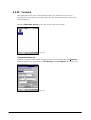
Key Input Mode Switchover
The F4/Alpha Key on the keyboard can be used to change the key input mode.
Indication of Key Input Mode
Key input mode currently specified appears in the task tray. The modes that can be displayed are
“L” as Lock, “F” as function, “1” as numeral, “A” as alphabets in uppercase, and “a” as alphabets
in lowercase.
L
F
1
A
a
Fig. 3.2
Turnover Key Auto Confirmation
After inputting a turnover key, if the preset time period has been elapsed from the time when the
turnover key is released, the turnover character input will be automatically made. The control
panel can be used to set up “enable” or “disable” for the auto confirmation on the turnover
character input and to set up the time period until when its confirmation is made.
Key Repeat
Continued pressing of any of “0” to “9” keys will repeat the key input.
Key Click Sound
The key click sound is generated when a key is pressed. However, it is not generated when the key
is released or in mid-course of repeating the key input. The control panel can be used to set up the
sound to mute, low or loud.
46
Enabling/Disabling Fn Key
For keys that perform specialized operations while the key input mode has been set to Function
mode, “Enable” or “Disable” can be set on each individual key in the registry below to control the
operations.
[HKEY_LOCAL_MACHINE\HARDWARE\DEVICEMAP\KEYBD]
Table 3.7
Key
DisableFn9
DisableFn8
DisableFn7
DisableFn6
DisableFn5
DisableFn4
DisableFn3
DisableFn2
DisableFn1
DisableFn0
DisableFnCLR
DisableFnF4
DisableFnF3
DisableFnF2
DisableFnF1
Setting Value
dword: 0/1
dword: 0/1
dword: 0/1
dword: 0/1
dword: 0/1
dword: 0/1
dword: 0/1
dword: 0/1
dword: 0/1
dword: 0/1
dword: 0/1
dword: 0/1
dword: 0/1
dword: 0/1
dword: 0/1
Meaning
Enable/Disable
Enable/Disable
Enable/Disable
Enable/Disable
Enable/Disable
Enable/Disable
Enable/Disable
Enable/Disable
Enable/Disable
Enable/Disable
Enable/Disable
Enable/Disable
Enable/Disable
Enable/Disable
Enable/Disable
Note:
Perform a reset on the terminal to make the changes in the registry effect in the actual operations.
Function Mode Notification
When the Fn key is pressed, the WM_USER+0x502 message is issued to the application. This
enables the application to detect whether the Function mode has been set up enabled or disabled.
Enable/Disable the Fn/□Key
The Common Device Control Library can be used to make the setting on “Enable” or “Disable”
for switching over the key input mode in application.
F4/Alpha Key Notification
When the F4/Alpha key is pressed, the WM_USER+0x506 message is issued to the application.
Using this notification, the application can detect whether the key input mode has been changed.
Permit/Prohibit Key Locks
The device library can be used to permit or prohibit the operations of keys except for the Power
and Trigger keys.
47
User Settable Keys
• Initiating application
The following registry can be used to assign any application to the Fn+7, Fn+8 and Fn+9 keys.
[HKEY_LOCAL_MACHINE\HARDWARE\DEVICEMAP\KEYBD]
Table 3.8
Key
Fn7LaunchPath
Fn8LaunchPath
CardLaunchPath
Setting Value
sz: Target application in full path to initiate
sz: Target application in full path to initiate
sz: Target application in full path to initiate
The following registry can be used to assign any application to the F1, F2, F3 and F4 keys.
[HKEY_LOCAL_MACHINE\Software\Microsoft\Shell\Keys]
Table 3.9
Key
40C1
40C2
40C3
40C4
Setting Value
sz: Target application in full path to initiate
sz: Target application in full path to initiate
sz: Target application in full path to initiate
sz: Target application in full path to initiate
• Programmable key codes
Returns the VK code set in the registry (Default: VK_F25).
[HKEY_LOCAL_MACHINE\HARDWARE\DEVICEMAP\KEYBD]
Table 3.10
Key
ProgKeyCode
Setting Value
DWORD
• Setting key codes
The Common Device Control Library can be used to assign any key code to all the keys except
the Fn key. Setting on “Enable” or “Disable” for assigning key code is possible either using the
Common Device Control Library or at the control panel.
The key codes after setting are effect only when the numeral input mode is set enabled.
48
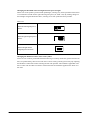
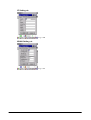
3.1.4 Touch Panel
An input can be made into any portion of the screen on the touch panel. The touch panel has the
following resolutions.
Table 3.11
Resolution
•
•
X direction
Y direction
240 dots
320 dots
Capturing touch coordinates, X and Y directions, and controlling the pointing are possible by
application.
Prior to using the touch panel for the first time, calibrating the touch panel is required.
Tap Sound
The Control Panel can be used to set up the tap sound to mute, low or loud.
Tap and Hold
By tapping and holding onto a specific object on the screen, the related pop-up menu will appear.
Rotating Touch Panel Coordinates
When the screen is rotated, the coordinates of the touch panel will also rotate in unison.
Touch Panel Calibration
Calibration on the touch panel can be initiated either using the Welcome wizard appeared after
full reset or by pressing simultaneously Fn and 4 keys.
The touch panel may require periodical calibration if it slipped off due to aged deterioration,
voltage fluctuation and/or temperature change, etc. If it does, adjust the calibration using one of
the methods.
49
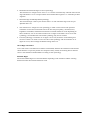
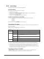
3.1.5 Audio
Basic Specifications
WAV playback, and voice recording are supported.
Stereo data is converted into mono data and then output. By using the Microsoft SoftwareMixer
function, output sounds from multiple applications can be mixed and output (in 44.1 KHz, 16-bit
stereo mixing).
The terminal supports WAV standards.
Playback
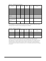
Table 3.12
Sampling
frequencies
Stereo/Mono
KHz
8
11.025
12
16
22.05
24
Mono
Yes
Yes
Yes
Yes
Yes
Yes
Stereo
Yes
Yes
Yes
Yes
Yes
Yes
Sampling frequencies other than those above are not supported.
8-bit or 16-bit
In reality, mono speakers do not playback in stereo.
32
Yes
Yes
44.1
Yes
Yes
48
Yes
Yes
KHz
8
11.025
12
16
22.05
24
Mono
Yes
Yes
Yes
Yes
Yes
Yes
Sampling frequencies other than those above are not supported.
8-bit or 16-bit
Mono input only via microphone
32
Yes
44.1
Yes
48
Yes
Recording
Table 3.13
Sampling
frequencies
Stereo/Mono
Setting Sound Volume
The Control Panel can be used to set up sound volume in six grades from loud to low and
ON/OFF of mute. Note, however, that the shutter sound setting is not allowed to change. A sound
volume also can be set up using Win32 API function in application.
50
3.1.6 Buzzer
Basic Specifications
The buzzer can be used to output various sounds such as scanning confirmation, key click, tapping,
alarm, warning and any other available sounds.
The buzzer sounds are not output to the headphones. To output them to the headphones, instead of
the buzzer sound, use PlaySound() API function which uses the audio driver. The sounds have
the following six attributes and default values.
Table 3.14
Sound Type
Tap sound
Key click sound
Alarm sound
Warning sound
Scan end sound
User defined sound
Frequency
(Hz)
2200
2600
2800
3000
3100
--
Time
(millisecond)
25
50
150
100
75
--
Individual Mute
Attribute
ON/OFF
ON/OFF
ON/OFF
ON/OFF
ON/OFF
ON/OFF
B_TAP
B_CLICK
B_ALARM
B_WARNING
B_SCANEND
B_USERDEF
Setting Volume
The Control Panel can be used to set up volume in three grades from loud, medium and low and
ON/OFF of mute. Setting the volume is also possible using the Common Device Control Library
in application.
51
3.1.7 Memory Management
RAM
The integrated RAM has a total capacity of 64 Mbytes and is used for the following purposes.
• Program memory to be used by the OS and programs.
• Object store used for temporary file saving, etc.
• Other program and OS resident areas beyond the control by the OS
• Buffers for display and camera
• Driver work area
The user can make unrestricted use with the object store, but data stored in it may be lost due to
battery exhaustion, etc. To avoid such incident it should be used just as a temporary storage area,
and use FlashDisk to store important data files.
Table 3.15
Initial memory status
Memory
Program memory capacity
Object store capacity
•
•
Initial Status
Total capacity; 30.85 MB
Total capacity; 30.85 MB
5.2 MB used
0.3 MB used
Of the 64Mbytes of RAM, apart from the above, it is used for OS resident area, buffers for
display and camera and driver work.
In a situation where there is a small open area in the program memory capacity, but a large
user application, the Control Panel can be used to reallocate the memory capacity. However,
in this case, back up for the setting after the change made for allocating the memory capacity
is not possible. If backup for the setting made on the Control Panel is required, use a “Backup
Tool” available from CASIO.
52
FlashDisk
The Flash Disk has 128MB as its total capacity. The disk is released as user disk and can be
accessed as FlashDisk folder. The user disk is available to freely read/write user data such as user
application, master data, transaction data, etc.
The Flash Disk different from RAM does not require a power to back up data in the disk, so data
is not lost even if the terminal’s memory backup battery is exhausted. Be sure to back up
important data files in the RAM to the Flash Disk.
The storage manager in the Control Panel is used for formatting and its management for the Flash
Disk. It is approximately 120MB when the default settings are used to format on the disk. (The
size may alter depending on the Flash Disk conditions.)
If the disk cannot be recognized, it is automatically formatted. This failure to recognize the disk
may not mount the disk itself. The failure does not allow the storage manager in the Control Panel
to perform formatting, and consequently there is no way of mounting the disk again.
To avoid this difficulty, the disk is automatically formatted if it cannot be recognized at time of
resetting. Prior to starting the formatting, a message will appear to ask the user “Yes” or “No” to
continue.
53
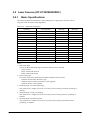
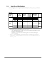
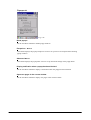
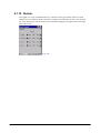
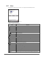
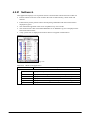
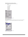
3.1.8
LED
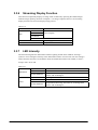
Basic Specifications
There are two LEDs integrated in the terminal, one for the user notification on the right and the
other for charging the battery complete on the left.
Table 3.16
LED
Right-side LED
Left-side LED
Color
Red
Green
Red
Green
Orange
Description
Charging battery pack
Charging battery pack complete
User notification (alarm)/Scanning a bar code
Scanning a bar code
None
Notes:
• The user notification LED can be used to indicate various notifications by the OS and other
notifications defined by the user.
• All colors available in the LEDs are indicated by using the Common Device Control Library.
• The charging battery complete LED cannot be controlled for its ON/OFF state with software.
User Notification (Alarm)
This indication mode is used for alarm notification, etc. The LED can be lit for a specific time
using CeSetUserNotification()API function.
Table 3.17
Specifications
Operating mode
Blink interval
Specification
ON for 1 second in red, OFF for 2 seconds
Note:
Indication for scanning a bar code has the priority over other indications.
Scanning
This is used for notification of a scanning result which is controlled by use of the Common Device
Control Library.
Table 3.18
Specifications
Operating mode
Scanning complete
Scanning in error
Specification
ON in green for a specified period of time, then OFF.
ON in red for a specified period of time, then OFF.
54
Attribute
L_SCANOK
L_SCANERR
User Definition
This indication mode is used for other notifications freely defined by the user. The ON/OFF state
can be controlled by use of the Common Device Control Library.
Table 3.19
Specifications
Operation mode
User definition
Specification
Color selection from green, blue, or orange.
Programmable for ON and OFF time periods
Note:
Indication for scanning a bar code has the priority over other indications.
55
3.2 Laser Scanner (DT-X11M10E/M10RC)
3.2.1
Basic Specifications
The following industrial standard bar code symbologies are supported by the laser scanner
integrated in the terminal (model dependant).
Table 3.20
Supported symbologies
Symbology
EAN, JAN,UPC-A/B
EAN, JAN,UPC-A/B Addon
UPC-E
UPC-E Addon
Code39
NW-7
Interleaved 2of5
Industrial 2of5
Code93
Code128
MSI
IATA
RSS-14
RSS Limited
RSS Expanded
Check Digit Sum
Enable/Disable
Enable/Disable
Enable/Disable
Enable/Disable
Enable/Disable
Enable/Disable
Enable/Disable
Enable/Disable
Enable/Disable
Enable/Disable (note 1)
Enable/Disable (note 2)
Enable
Enable
Enable
Min Digits
8 (fixed)
10 (fixed)
7 (fixed)
9 (fixed)
2 (note 3)
2 (note 4)
4 (note 5)
2
1
1
1
1 (note 6)
14 (fixed)
14 (fixed)
1
Max Digits
13 (fixed)
18 (fixed)
7 (fixed)
12 (fixed)
47
62
92
55
77
98
67
44 (note 6)
14 (fixed)
14 (fixed)
74 (note 7)
Notes:
1. MSI check digit
One of the three MSI check digit calculation methods can be selected.
- 1 digit, mod10
- 2 digit, mod10 and mode10
- 2 digit, mod10 and mod10
2. IATA check digit
One of the three IATA check digit calculation methods can be selected.
- Calculate number other than end 1 digit
- Calculate coupon number and numeric value segment
- Calculate numeric value segment
3. Minimum digit on Code39 symbology
The minimum no. of digits can be set to one only when scanning on Code39 symbology is
enabled.
4. Minimum digit on NW-7 symbology
The minimum no. of digits can be set to one only when scanning on NW-7 symbology is
enabled.
5. Minimum digit on Interleaved 2of5
The minimum no. of digits can be set to two only when scanning on Interleaved 2of5
symbology is enabled.
56
6. Minimum and maximum digits on IATA symbology
The minimum no. of digits can be set to 15 or 17 for the maximum only when the IATA check
digit calculation is set to “Coupon number and Calculate data segment” or “Calculate just data
segment”.
7. Maximum digit on RSS Expanded symbology
The maximum digit count for just numeric data is 74. The maximum digit count for just
alphabet data is 41.
•
•
The maximum no. of digits for each symbology in Table 3.20 is based on the optimum
conditions of each relevant element such as the bar code print quality, resolution, PCS,
brightness surrounded, and distance between the terminal and the bar code. Depending on
these conditions, even if one of the maximum no. of digits in the table is set to a bar code
symbology, an individual bar code of that symbology may not be scanned.
If IATA symbology’s minimum no. of digits is set to one, the chance of misreading will
increase. If there is no need to scan a bar code of the symbology with its minimum no. of
digits set to one, do not change the default setting which is 4.
Check Digit Calculation
A bar code value is calculated in accordance with method, and then the calculation result and the
check character at a specific position are compared. If they match, the scanning data is deemed
correct. The calculation method differs according to each symbology.
Readable Digits
The actual readable digit on a bard code differs depending on the resolution and the scanning
distance between the terminal and the bar code.
57
3.2.2
Scanning Method
The laser scanner has “scanning state” (emits laser beam to read a bar code) and “standby state”
(scanning is halted and in standby state). These two states are controlled to start scanning bar code
and stop the scanning.
Table 3.21
Scanning methods
Scan method
Single scan
Continuous scan
(controlled with
trigger key)
Continuous
scanning
(controlled by
program)
Description
Conditions for scanning to end
Press the trigger key to start
scanning. Scanning is stopped
when either scanning is
succeeded or one of the scan end
conditions is met.
Press the trigger key to start
scanning, and scanning will
continue as long as the trigger
key is pressed down.
Scanning will stop when either
scanning is completed for just
preset no. of times for scanning
or one of the scan end conditions
is met.
Scanner library functions are
used to start and stop scanning.
The previous scanning data and
scanning data overlapped with
other scanning data will be
disregarded. Also, to save the
power during scanning, emitting
laser beam will be turned off
between laser emissions. (see
note)
Timeout
Yes/No
- Timeout time has elapsed.
- OBRClose function is called.
Yes
- Timeout time has elapsed after scanning
a bar code.
- Scanning for the number of preset times
is complete.
- The trigger key is released.
- OBRClose function is called.
- Timeout time has elapsed after scanning
the precious scanning.
- Scanning end function is called while
scanning continues.
- OBRClose function is called.
Yes
Yes
Note:
The scanning method set as default is with “Continuous scanning (controlled with trigger key)”
and “No. of preset times for continuous scanning = 1”.
Step Scan
This method is for scanning a designated number of bar codes. Once scanning for the designated
number of bar codes has been completed, the scanner will close and not scan again until reopened.
Also, the same bar codes that have been scanned previously cannot be scanned again.
58
3.2.3
Scanning Parameters
Conditions that allow scanning a symbology in specific modes can be set for each readable
symbology.
Readable Symbology
Bar code symbologies that are enabled or disabled for scanning can be specified.
If only specific symbologies are to be scanned, set “Enable” for scanning on these symbologies
only and “Disable” on the other symbologies. This will reduce decode processing time and lower
the error rate. The default is “Enable scanning on all the symbologies”.
Readable Digits
The no. of readable digits can be set for each symbology.
If only specific no. of digits is to be scanned, specify it for each readable symbology. This will
reduce decode processing time and lower the error rate.
Enable/Disable Check Digit
Check digit can be set to “Enable” or “Disable” for each readable symbology. Setting the check
digit will lower the error rate.
Table 3.22
Symbology
EAN, JAN,UPC-A/B
EAN, JAN,UPC-A/B Addon
UPC-E
UPC-E Addon
Code39
NW-7
Interleaved 2of5
Industrial 2of5
Code93
Code128
MSI
IATA
RSS-14
RSS Limited
RSS Expanded
Check Digit Calculation
Enable/Disable
Enable/Disable
Enable/Disable
Enable/Disable
Enable/Disable
Enable/Disable
Enable/Disable
Enable/Disable
Enable/Disable
Enable/Disable
Enable/Disable
Enable
Enable
Enable
Default
Enable
Enable
Enable
Enable
Disable
Enable
Enable
Enable
Enable
Enable
Disable
Enable
Enable
Enable
Validation
Validation is carried out for a specified number of times to check if scanned data is valid, and then
the data is output only if it is valid. The number of validations can be set in the range of 1 to 9
either at the Control Panel or using the Common Device Control Library. The default is 3.
59
No. of Scanning Times
In “Continuous Scanning” mode, scanning continues for the preset number of scanning times and
then it will stop in waiting mode. The number of times for scanning can be set in the range of 1 to
9 either at the Control Panel or using the Common Device Control Library. The default is 1.
Scanning Period
Valid time period of scanning after the trigger key is pressed down can be set in the range of 1 to
9 either at the Control Panel or using the Common Device Control Library. After the preset time
has elapsed, the scanner will go into standby mode waiting for the trigger key to be pressed down
again. The default is 3 seconds.
Double Scanning Prevention
This is used to prevent double scanning of the same bar code during the “Continuous Scanning”
mode is being set. Scanning the same bar code again will be prohibited as long as the scanning
continues for the preset number of times. However, it can be scanned when a new “Continuous
Scanning” starts.
60
3.2.4
Scanning Output Format
Formats for outputting results of scanned bar codes can be set.
Table 3.23 Output Formats
Symbology
Standard
digits
Output Format
JAN-13
13
FFMMMMMNNNNNCT
EAN-13
13
FFMMMMMNNNNNCT
JAN-8
8
FFMMMNCT
EAN-8
8
FFMMMNCT
15
FFMMMMMNNNNNCAAT
15
FFMMMMMNNNNNCAAT
18
FFMMMMMNNNNNCAAAAAT
18
FFMMMMMNNNNNCAAAAAT
10
FFMMMMNCAAT
10
FFMMMMNCAAT
13
FFMMMMNCAAAAAT
JAN-13
addon+2
EAN-13
addon+2
JAN-13
addon+5
EAN-13
addon+5
JAN-8
addon+2
EAN-8
addon+2
JAN-8
addon+5
EAN-8
WPC
No. of
Remark
See Table 3.24 "WPC symbology” for
meanings of the notations.
Excluding UPC-B, check digit (mod
10) calculation is always performed
13
FFMMMMNCAAAAAT
UPC-A
12
0SMMMMMNNNNNCT
UPC-B
12
0SMMMMMNNNNNNT
14
0SMMMMMNNNNNCAAT
14
0SMMMMMNNNNNNAAT
17
0SMMMMMNNNNNCAAAAAT
17
0SMMMMMNNNNNNAAAAAT
12
SMMMMMNNNNNCT
14
SMMMMMNNNNNCAAT
17
SMMMMMNNNNNCAAAAAT
JAN-13
14
0FFMMMMMNNNNNCT
GTIN
EAN-13
14
0FFMMMMMNNNNNCT
GTIN
addon+5
UPC-A
addon+2
UPC-B
addon+2
UPC-A
addon+5
UPC-B
addon+5
UPC-A
UPC-A
addon+2
UPC-A
addon+5
JAN-8
14
0000000FFMMMNCT
GTIN
EAN-8
14
0000000FFMMMNCT
GTIN
UPC-A
14
00SMMMMMNNNNNCT
GTIN
Continue.
61
Symbology
Standard
UPC-E
UPC-E
UPC-E
(see note)
No. of
digits
NW-7
Remark
(7),8
0MMNNNMCT
(7),8
0MMMNN3CT
(7),8
0MMMMN4CT
(7),8
0MMMMMNCT
Last N: 5 to 9
(6),7
MMNNNMCT
Last M: 0 to 2
(6),7
MMMNN3CT
(6),7
MMMMN4CT
(6),7
Last M: 0 to 2
MMMMMNCT
Last N: 5 to 9
14
0000000MMNNNMCT
GTIN Last M: 0 to 2
14
0000000MMMNN3CT
GTIN
14
0000000MMMMN4CT
GTIN
14
0000000MMMMMNCT
GTIN Last N: 5 to 9
(9),10
0MMNNNMCAAT
Last M: 0 to 2
(9),10
0MMMNN3CAAT
(9),10
0MMMMN4CAAT
UPC-E
(9),10
0MMMMMNCAAT
Last N: 5 to 9
addon+2
(8),9
MMNNNMCAAT
Last M: 0 to 2
(8),9
MMMNN3CAAT
(8),9
MMMMN4CAAT
(8),9
MMMMMNCAAT
Last N: 5 to 9
(12),13
0MMNNNMCAAAAAT
(12),13
0MMMNN3CAAAAAT
(12),13
0MMMMN4CAAAAAT
UPC-E
(12),13
0MMMMMNCAAAAAT
Last N: 5 to 9
addon+5
(11),12
MMNNNMCAAAAAT
Last M: 0 to 2
(11),12
MMMNN3CAAAAAT
(11),12
MMMMN4CAAAAAT
(11),12
Code39
Output Format
Last M: 0 to 2
MMMMMNCAAAAAT
Last N: 5 to 9
3 to Max
SBBB ------- BBCST
See Table 3.25 "Code39 symbology”
3 to Max
SAAA ------- AACST
for meanings of the notations.
1 to Max
BBB ------- BBCT
1 to Max
AAA ------- AACT
3 to Max
SDDD ------- DDDST
See Table 3.26 "NW7 symbology” for
1 to Max
DDD ------- DDDT
meanings of the notations.
See Table 3.27 "Interleaved 2of5
Interleaved
2of5
symbology” for meanings of the
2 to Max
DDD ------- DDDCT
notations.
Only the no. of digits in even number
is allowed for readable digits.
See Table 3.28 "Industrial 2of5
Industrial
2of5
symbology” for meanings of the
2 to Max
DDD ------- DDDCT
notations.
Only the no. of digits in even number
is allowed for readable digits.
Continue.
62
Code93
Code128
Code128
AAA ------- AAAT
1 to Max
AAA ------- AAAT
1 to Max
SBBB ------- BBCST
See Table 3.30 "Code128 symbology”
1 to Max
AAA ------- AAAT
for meanings of the notations.
1 to Max
SBBB ------- BBCST
1 to Max
FAAA ------- AAAT
1to Max
GAAA ------- AAAT
MSI
1 to Max
DDD ------- DDCCT
IATA
1 to Max
EAN-128
See Table 3.29 "Code39 symbology”
1 to Max
RSS-14
RSS
Limited
RSS
Expanded
for meanings of the notations.
See Table 3.31 "EAN128 symbology”
for meanings of the notations.
See Table 3.32 "MSI symbology” for
meanings of the notations.
DDDDDDDDDD ------- CT
See Table 3.33 "IATA symbology” for
PADDDDDDDDDDDDDDCT
meanings of the notations.
16
01DDDDDDDDDDDDDCT
See Table 3.34 "RSS-14 symbology”
14
DDDDDDDDDDDDDCT
for meanings of the notations.
16
01DDDDDDDDDDDDDCT
See Table 3.35 "RSS Limited
14
DDDDDDDDDDDDDCT
1 to74
DD ------- DDDT
1 to 41
AAA ------- AAT
symbology” for meanings of the
notations.
See Table 3.36 "RSS Expanded
symbology” for meanings of the
notations.
Note:
If the no. of scanning digits described in parentheses, “C” will not be appended to the output.
Table 3.24 WPC symbology
F
M
N
S
A
T
C
Country flag
Manufacturer code
Product code
Number system character
Addon data
Termination code
Check digit (mod 10)
Table 3.25 Code39 symbology
A
B
ASCII conversion post data
ASCII conversion pre data
C
Check digit (mod 43)
Becomes data if there is no check digit
S
T
Start/Stop character
Termination code
Table 3.26 NW7 symbology
S
D
T
Start/Stop character (any of a, b, c, d)
Data
Termination code
63
Table 3.27
D
C
T
Data
Check digit (mod 10)
Becomes data if there is no check digit
Termination code
Table 3.28
D
C
T
Interleaved 2of5 symbology
Industrial 2of5 symbology
Data
Check digit (mod 10)
Becomes data if there is no check digit
Termination code
Table 3.29 Code39 symbology
A
B
ASCII conversion post data
ASCII conversion pre data
C
Check digit (mod 47)
Becomes data if there is no check digit
S
T
Start/Stop character
Termination code
Table 3.30 Code128 symbology
A
B
T
ASCII conversion post data
ASCII conversion pre data
Termination code
Table 3.31 EAN128 symbology
C
S
F
G
T
Check digit (mod 47)
Start/Stop character
Code ID (only “]C1”, EAN128)
GS (only 1Dh, EAN128)
Termination code
Table 3.32 MSI symbology
D
C
T
Data
Check digit (mod 10, mod 11)
Becomes data when there is no check digit
Termination code
Table 3.33
D
C
P
A
T
IATA symbology
Data
Check digit (IATA)
Becomes data when there is no check digit
Coupon No
Airline No
Termination code
64
Table 3.34 RSS-14 symbology
D
C
T
Numeric data
Check digit (mod 10)
Termination code
Table 3.35 RSS Limited symbology
D
C
T
Numeric data
Check digit (mod 10)
Termination code
Table 3.36 RSS Expanded symbology
D
A
T
Numeric data
Alphabet data
Termination code
65
Termination Codes
Select one of the following five termination codes to attach to the end of decoded data.
- CR
- LF
- CR+LF
- TAB
- No termination code
The default is “No termination code”.
Output Buffer
The scanner scans a bar code and outputs the scanned data using one of the following methods
described in the table below.
Table 3.37
Output Method
OBR buffer output
(see note)
Key message output
Clipboard output
Keyboard output
-
Description
Scanned data is output to memory in the laser scanner driver.
Scanned data already output to the memory can be captured using the Common
Device Control Library.
Scanned data can be output with the window message to the specified window handle.
The window handle is specified using the Common Device Control Library.
Scanned result is copied to the clipboard and then output to the edit control focused by
caret.
Scanned result is output as a keyboard event to the edit control focused by caret.
Note:
When a bar code is scanned, the decoded data including the symbology and data size are stored to
the memory in the laser scanner driver. This output method has the following features.
• Can capture the bar code symbology and data size.
• Can capture the data at any timing the user prefers.
• One piece of data can be a maximum of 98 characters long and up to nine labels can be stored
in the memory. If any new data scanned after exceeding over nine labels stored already in the
memory will be disregarded.
Conditions for Terminating Scanning
Scanning will be terminated when any of the following conditions is met.
• Scanning is succeeded.
• Preset timeout period has elapsed.
• OBR buffer becomes a full.
• An abnormal condition is detected in the scan module.
66
Scan Completion Notification
When scanning is completed, a notification is issued to the application using one of the methods
described in the table below. Each notification method can be set to “Enable” or “Disable”. The
default is “Notification with window message”.
Table 3.38
Method
Window message
Event
None
Description
A window message is issued to the specified window handle. Also, the conditions for
scanning completion can be fetched by referring to wParam parameter of the window
message.
A predefined event in the registry is issued. The conditions of scanning completion can
be fetched using the Common Device Control Library.
No message or event is issued when scanning is complete.
Event Name
The predefined event name which is issued for event notification can be changed in the registry
described below. If there is no value set in the registry, the default event name
OBRScanningEvent will be used.
[HKEY_LOCAL_MACHINE\Drivers\CASIO\Laser]
Table 3.39
Key Name
EventName
Setting Value
sz: Any name
Capturing Event Factors
When a notification for scanning completion is issued with “Event”, factors which made the
scanning succeeded are automatically recorded. The recorded factors are also fetched using the
Common Device Control Library.
67
3.2.5
Scan Result Notification
When scanning a bar code is completed, a notification about the scanning result can be indicated
to the user with either LED or buzzer or vibration. Each indication method can be set to “Enable”
or “Disable”.
Table 3.40
Indication
method
Setting
LED
Mode 1
Mode 2
Mode 3
(disable)
Buzzer
Vibration
Enable
Disable
Enable
Disable
When
succeeded
When failed
(see note 1)
ON in green
ON in green
None
ON in red
Scanning
interrupted
(Trigger key
released)
None
None
None
None
None
None
None
None
Warning sound
None
None
None
None
None
None
None
None
None
Scan
completion
sound
None
Vibrate
None
OBR buffer full
(see note 2)
ON in green
ON in green
Default
Mode 1
Enable
Disable
Notes:
• Scanning will fail when one of the following errors occurs.
A bar code with the number of digits which exceeds over the specified range is scanned.
Check digit calculation error occurs.
Full ASCII conversion error occurs in scanning bar code of Code39 symbology or
Code128 symbology.
• During the “OBR buffer output” method has been set as scanned data output method, this
condition occurs if scanning takes place while nine labels worth of data are stored already in
the memory buffer.
68
3.2.6
Expanded Features
Power ON with Trigger Key
If the Trigger key has been set to “Enable turning on the power with Trigger key”, the power can
be turned ON (while the power was being turned off) when it is pressed down. This function
allows the user to achieve three-step operation with only one action, (1) turn on the power → (2)
press the Trigger key → (3) scan a bar code. This feature is a perfect idea when the user wishes to
resume scanning after the power has been turned off. The default is “Disable turning on the power
with Trigger key”.
Setting Trigger Key
4-way cursor key and side trigger keys can be set as the Trigger key. The default is only both left
and right side keys are set as the Trigger key.
Noise Filter
If the background of a bar code is white color, a noise tends to be generated easily during
scanning causing the error rate to increase. To reduce such the noise, the noise filter function is
available with the terminal. Two methods are available to set the function operable.
Table 3.41
Filter
Description
Merit
Demerit
A software process removes noise. In determining the
Effective when
If initial bar is
blank at the leading edge of the bar code, if there is a
scanning leading
extremely thin, it
bar width smaller than a certain value, it will be
edge blank of bar
will be determined
Software
bonded to the fore and aft data, the noise eliminated
code using laser
as noise and
noise filter
and the determination made. Also, the time from scan
module noted for
eliminated, which
start to “enable” of software filter can be set in the
easily picking up
may mean that the
range of 1 to 8 seconds. The default is 3 seconds.
noise.
bar code cannot be
scanned.
A noise is removed with the laser module process by
Effective for bar
Not recommended
Hardware
narrowing the frequency band width of detecting bars
code symbol with
for bar code symbol
noise filter
of a bar code symbol. This process makes a noise to
poor resolution.
with high resolution.
be generated less.
Note:
The software noise filter is not effect with the DT-X11 series.
Configuration File
The various setting parameters related to scanning bar code symbols can be stored in a file
(configuration file) and then resumed. The configuration file storage path and its file name are
“\FlashDisk\System Settings\OBRDRV.ini”. If there is no such the configuration file existed, the
default values are used to initiate scanning.
69
Dual Decoder System
The dual decoder system integrated in the terminal initially decodes a scanned bar code data using
the standard decoder, but if the decoding fails, it will use the additional decoder described below
to decode the same bar code data. This dual decoders system supports the bar code symbologies
listed below.
- Code39 symbology
- Code128 symbology
- EAN symbology
With the decoding system used for the previous CASIO handheld terminals, decoding is processed
with a mean value of one module adding bar thickness of each black bar and white bar for one
character when performing binaryzation or quardruplzation of bar thickness. However, this
method does not accurately decode a bar code if it is formed with unbalanced bar thickness
between white bars and black bars.
The dual decoder system can solve it by calculating separately each mean value of black bars and
white bars for such a bar code with unbalanced thickness of white and black bars by changing the
threshold level of decoding.
Customizing the Decoder
According to the scan environment and the bar code printed material’s quality, the integrated
decoder can be customized for efficient scanning performance. First, to maintain scanning
performance with the ordinary decoding logic, perform decoding using the decoder and if it does
not succeed, customize it by tuning the elements in the table below so that the decoding can be
performed better.
Table 3.42 Customizing the elements
Element
Change margin of the right/left
threshold values
Change of compensation values
of the thickness of bars of a bar
code symbol.
Description
Used to change the threshold values for right and left side marginal
spaces of a bar code symbol printed inside quadrangle.
Used to thicken or thin each bar of a bar code symbol for a specified
value and then decode it.
Value for thickening or thinning bars that form a bar code symbol can be
changed.
70
Changing the threshold values for Right and Left space margins
When a bar code symbol is printed inside quadrangle, scanning may not be possible because there
is not sufficient left side and/or right side marginal space (see Table 3.43). By making change on
the left/right marginal threshold values, scanning a bar code symbol becomes possible.
Table 3.43
When the left marginal space is
narrow.
When the right marginal space is
narrow.
When both right and left
marginal spaces are narrow.
Changing the thickness of bars of bar code symbol
If bars of a bar code are printed thick because blurring or scratchy white bars (spaces between two
bars) are printed thinly, the bar ratio will not be correct causing scanning incorrectly. By adjusting
the thickness of these bars makes scanning the bar code possible. This method is applicable if all
bars of a bar code are either too thick or too thin because the method is applied to the whole of a
bar code.
71
Decoder learning function
This function is to automatically change parameters for criteria and threshold level used to judge
on decoding bar code data so that scanning a bar code printed in poor quality can be improved.
However, after changing the relevant parameters for the decoder learning function, the individual
scanning characteristics of each terminal may be degraded. To avoid such degrade, the integrated
decoding system starts decoding with the standard decoder and then changes with the customized
decoder if decoding at the first stage fails. If the decoding at the end of the process does not
succeed, the decoder learning function is used to ensure it to be succeeded. Setting either “Enable”
or “Disable” for the function to be effect can be set. See the decoding process flow in Fig. 3.3.
Decoding starts
With standard decoder
Yes
Decoding OK?
No
With customized decoder
Yes
Decoding OK?
No
Decoding with decoder learning function
Yes
Decoding OK?
No
Decoding fails
Decoding succeeds.
Fig. 3.3
72
Symbologies supported by the decoder learning function
Scanning performance can be improved with the decoder learning function for the following bar
code symbologies.
EAN, JAN,UPC-A/B
EAN, JAN,UPC-A/B Add on
UPC-E
UPC-E Add on
Code39
NW-7
Interleaved 2of5
Industrial 2of5
Code93
Code128
MSI
IATA
Parameter Precedence Change function
The operating order of the relevant parameters used in success decoding bar code data with the
decoder learning function can be advanced for precedence. This advance will result in quick
response of continuously scanning multiple bar codes with similar quality. Since the precedence
order will be stored in the RAM memory, it will be reset to the default order if RESET is
performed on the terminal.
Erratic Scanning Avoidance function
This function fetches the bar code quality rank by calculating the decoder easiness when scanning
a bar code. If the quality rank of scanned bar code is relatively low, the error rate will become
high causing an erratic scanning to occur. To suppress the error rate, the function automatically
makes judgment on scanning with such the bar code as “Failure”.
3.2.7
Power Control
In order to save the power, the power will not be supplied to the laser scan module and the ASIC
module for laser beam control during the laser beam is not irradiating. It will be supplied to these
modules when the laser beam is to be irradiated, and turned off again when the laser beam is not
irradiated.
73
3.3 CMOS Imager (DT-X11M30E/M30U/M30RC)
3.3.1
Basic Functions
With a monochrome CMOS imager, decoding and capturing of 1D bar code symbologies and 2D
code symbologies as well as images are supported. Not only a CMOS sensor, but also a red LED
for illumination and green LED for aiming are integrated.
3.3.2
Readable Symbologies
Table 3.44
1D bar code symbologies
Symbology
Minimum
Maximum
Check
digits
digits
character
Check
character
Output format/Add-on
function
output
EAN8/JAN8
8 (+2/5)
Enable
Enable/Disable
2 digits/5 digits added-on
EAN13/JAN13
13 (+2/5)
Enable
Enable/Disable
2 digits/5 digits added-on
UPC-A
12 (+2/5)
Enable
Enable/Disable
NS output
2 digits/5 digits added-on
UPC-E
6 (+2/5)
Enable
Enable/Disable
NS output
UPCA conversion
2 digits/5 digits added-on
Code39
1
22
Enable/Disable
Enable/Disable
Output of start/stop bit
Full ASCII conversion
Add-on code
Codabar(NW7)
2
26
Enable/Disable
Enable/Disable
Output of start/stop bit
Interleaved2of5
4
42
Enable/Disable
Enable/Disable
Code93
1
35
Enable
Disable
Code128/EAN128
1
28
Enable
Disable
Code A/B
Code C
(ITF)
1
56
Enable
Disable
MSI(Plessey)
4
26
Enable
Enable/Disable
IATA
4
24
Enable
Disable
Code11
1
40
RSS-14
Enable(2)
Disable
14
Enable
Disable
14
Enable
Disable
(Standard/Truncate
d)
RSS Limited
RSS Expanded
1
40
Enable
Disable
1
28
Enable
Disable
(Standard)
ISBT (see note)
Note:
ISBT symbology is decoded as Code128 symbology.
74
Table 3.45
2D Stacked code symbologies
Check
Minimum
Maximum
Check
digits
digits
character
Code49
1
81
Enable
Disable
PDF417
1
2,000
Enable
Disable
Symbology
character
Output format / Add-on
function
output
MicroPDF
1
366
Enable
Disable
Codablock F (see note)
0
200
Enable
Disable
EAN8/13 Composite
1
300
Enable
Disable
RSS Composite
1
135
Enable
Disable
UCC/EAN128
1
300
Enable
Disable
Composite
TLC39
-
RSS-14 (Stacked type)
279
14
Enable
Disable
Enable
Disable
Enable
Disable
included Standard Omni
directional
RSS Expanded (Stacked
1
20
type)
Note:
Since Codablock F is a stacked code of the Coda128 symbology, a part of symbol of the Code128
symbology may be read if the Code128 symbology is set to “Enable”.
Table 3.46
2D Matrix symbologies
Symbology
Minimum
Maximum
Check
digits
digits
character
Check
Output format / Add-on
character
function
output
Aztec
1
2,000
Enable
Disable
QR Code
1
1,500
Enable
Disable
Maxicode
1
138
Enable
Disable
DataMatrix
1
1,000
Enable
Disable
Model 2 only
ECC000/050/080/100/140/2
00
Note:
The maximum numbers of digits listed in the above table apply to cases where the entire
symbology consists of numeric characters only. The maximum number will be reduced to 2/3 of
each maximum no. of digits for alpha-numeric characters; and reduced to 1/3 for Kanji characters
and binary numbers. These are merely reference, and the actual range of readable symbologies
varies according to the conditions (resolution, PCS, etc.) of individual symbol and the surrounding
environment.
75
3.3.3
Read Assisting Functions
Multi-step Read
This function is used to continuously perform decoding as long as one of the Trigger keys (R) and
(L) is held down. Once bar codes are decoded they will not be read any more. This function is
useful for reading all bar codes without repeating the same action when more than one bar code is
printed on one slip.
Package Read
This function is used to output the read result obtained from more than one bar code in a package.
With the multi-step read function, once bar codes are decoded they will not be read any more.
This is useful for handling multiple pieces of bar code data. However, if any of the following
unfavorable conditions occur, all the bar codes may not be read in one capture:
• The objective bar code of read is not contained in the captured image.
• The focus is not sharp enough.
• The exposure is not correct.
Table 3.47 Difference between Multi-step and Package Reads
Performance
Maxi. no. of bar codes to read
Multi-step Read Mode
Package Read Mode
10
10
Max. no. of digits to read
4,095
4,095 (see note below.)
Total no. of digits to read
4,095 x 10 = 40,950
4,095
Continuously reads the specified
Multiple bar codes are read in a single scan.
number of bar codes as long as the
Neither the buzzer sounds nor the LED
Program key is held down. Different
turns on until the specified no. of bar codes
from Package read in which multiple
has been read.
(Max. no. of read steps)
Read method
bar codes are read at a single scan, a
single kind of a symbol will be
continuously read through multi read
steps. If one bar code is read, the buzzer
sounds and the LED turns on.
Recommended method
of use
This mode is suitable in the following
This mode is suitable in the following case:
cases:
- If multiple bar codes with small number
- If the bar code has many digits.
- If the target bar codes are spaced.
- To positively confirm a read.
of digits are adjacent to one another.
Note:
This terminal has been designed so that a maximum of 10 bar codes or 4,095 digits of bar codes
can be read. However, it is not recommended for the user to use the package read mode for
reading bar codes consisting of a large number of digits. If the number of bar codes is greater than
4, or if the total number of digits is greater than 100, use the multiple-step read mode as much as
possible.
76
Decode Deliberation
The deliberation of decoding can be set up in five scales. If it is set up to “Very Quick” or
“Quick”, the decoding speed becomes fast though the number of symbols to be decoded is limited
instead. Or, if it is set up to “Deliberate” or “Very Deliberate”, the speed becomes slow though the
number of symbols to be decoded is increased.
Table 3.48
Deliberation
Very Quick
Quick
Normal
Deliberate
Very Deliberate
Symbol to be read
1D bar code with a good quality
1D bar code with a bad quality
PDF417 in 500 digits or less.
PDF417, DataMatrix, QR, Aztec Code, MicroPDF, Code49,
Codablock F, Composite code and Maxicode in 1,000 digits
or less,
PDF417, DataMatrix, QR, Aztec Code in 1,000 to 2,000
digits. TLC39 in 80 digits or less.
RSS-14 Stacked /RSS Expanded Stacked
PDF417, DataMatrix, QR, Aztec Code in 2,000 digits or more
TLC39 in 80 digits or more
Decoding speed
Very fast
Fast
Normal
Slow
Very slow
Automatic Combination
The terminal supports the automatic combination of symbols for certain symbologies. The
supported symbologies are Code93, Code49 and QR Code. When the combination end symbol is
read or all symbols of any of these symbologies are read, the data are saved in the buffer and then
all the data are combined and then output.
Table 3.49
Symbology
Code93
Condition
A symbol with space at the
forefront of data
Code49
A symbol starting with the
mode 1(M=1) at the
forefront of data
A symbol with the
combination identifier
included
QR Code
Process to combine
- If a symbol with space at the forefront of data is read, the data is
saved in the internal buffer.
- And, other symbols with the space at the forefront are continued
to be read. All the read data are saved in the buffer and then
combined in order. The data are not output.
- Lastly, if a symbol staring with non-space data at the forefront is
read, the last symbol data is combined into other symbols in the
buffer and then all the combined symbols are output
The method of the process is the same with that of Code93
symbology. The difference is the forefront of data starting with
“M=1”.
Each symbol of the combination QR Code symbology
includes an identifier that can identify the number of
separations and “n th” symbol for the symbol. The decoder will
combine all the data in order by interpreting each identifier included
in the symbols after reading all the symbols, and output.
Note:
The three symbologies in the table are read only in the normal read mode. Reading the combine
symbologies in the multi-step read and package read modes is not possible.
77
Reading Binary data
Decoded data of scanned symbol can be output in binary data instead of character string data. This
enables to scan ciphered data and image, voice sound in binary data, character string delimited
with NULL character.
3.3.4
Image Capture Function
This function is used to capture image data and save it as a JPEG file.
Table 3.50
Reduction
Size
Scale
3.3.5
1/1, 1/2, 1/4
1/1 reduction
752 x 480 pixels
1/2 reduction
376 x 240 pixels
1/4 reduction
188 x 120 pixels
Partial extraction is possible.
2- or 256-gray scale
Signature Index Function
This function scans both symbol and signature at one time and outputs the symbol data and
indexed signature at the same time. The position and size of a signature can be specified in the
user application based on the position of the symbol. The applicable symbologies are Code39,
Nw7 (Codabar), Code128, PDF417 and Aztec.
Fig. 3.3
As shown above, a rectangular area relative to the center of the symbol will be indexed and output
as an image file.
78
3.3.6
Streaming Display Function
This function sequentially displays an image while continuously operating the CMOS Imager.
With the image capturing function in Chapter 3.3.4 “Image Capture Function”, the streaming
display function can be used to display image preview.
Table 3.51
Reduction
1/1, 1/2, 1/4
1/1 reduction
Size
Scale
Frame rate
3.3.7
188 x 120 pixels
1/2 reduction
1/4 reduction
Partial extraction is possible.
2- or 256-gray scale
30 fps or less
LED Intensity
The terminal integrates the illumination LED for lighting and the aimer LED for focusing a
symbol to scan. Setting the intensity of the illumination LED to zero will turn off. This setting is
useful when the terminal is used outdoor where the illumination LED is not needed, or when a
stamp in red is to be read.
Table 3.51
Illumination
Type
ON, OFF
Intensity adjustment
Aimer
Type
ON, OFF
Intensity adjustment
LED in red
Possible
Not possible for fine tuning. Set to either “0” for turning off the
LED or “100” for turning on.
LED in green
Possible
Not possible for fine tuning. Set to either “0” for turning off the
LED or “100” for turning on.
79
3.3.8
Imager’s APO
This function will shut down the power to the imager automatically if the imager has not been
used for a while. After activating the APO (Automatic Power OFF) function, the imager’s power
can be turned on again if one of the following functions is invoked. The time period of the APO
function can be set up in the range of 0 to 1,800 seconds. Specifying “0” will disable it. The power
consumption by the imager can be curbed while the APO function is activating. However, note
that it takes about 30 milliseconds to put the power back on.
•
•
•
•
•
•
•
3.3.9
Scan a symbol.
Assist scanning symbol.
Scan an OCR font.
Capture an image.
Index a signature.
Stream display.
Adjust CMOS imager.
Scan Result Notification
The notification of the read completion of a symbol can be posted using one of the following two
integrated devices. The buzzer sound level can be set up at the Control Panel.
Table 3.52
Device
LED
Buzzer
Setting
Read succeeded
Read failed
Mode 1
Mode 2
Invalid
Valid
Invalid
Lit in green
Lit in green
None
Sound
None
Lit in red
None
None
None
None
80
Read terminated
(release the Trigger key)
None
None
None
None
None
Remark
Default
Default
3.4 USB
3.4.1
Basic Specifications
USB Client (USB Function)
• Supports the USB 1.1 full speed.
• Communication with PC can be established via “wceusbsh.dll”.
• Communication with PC can be established via ActiveSync.
• Communication with PC can be established via FLCE / LMWIN (ActiveSync must be
disabled.)
T
3.4.2
COM Port
COM port used via USB is as follows.
Table 3.52
USB Function
3.4.3
COM5
Product ID
The USB product ID is as follows.
Table 3.53
USB Client
0x3303
81
T
T
T
3.5 IrDA
3.5.1
Communication Speeds
The IrDA supports the following physical communication speeds.
Table 3.54
Via
IrDA protocol
RAW IR
SIR
9600, 19.2K, 38.4K, 57.6K, 115.2K bps
9600, 19.2K, 38.4K, 57.6K, 115.2K bps
FIR
4M bps
-
Notes:
• A speed of communication via IrDA protocol is automatically determined by negotiation with
the partner device.
• The maximum communication speed supported commonly by both parties (the terminal and
the partner device) will be determined as communication speed.
• Communication speed cannot be set in application.
3.5.2
COM Port
COM ports used via IrDA are as follows.
Table 3.55
IrDA protocol
RAW IR
COM3
COM4
82
3.6 Bluetooth
3.6.1
Basic Functions
Master
The terminal (“Master”) establishes a connection with a Bluetooth equipment in slave mode.
Slave
The terminal (“Slave”) is in waiting mode for communication to be established by the master.
Security/Encryption
Performs security (PassKey exchange) and encryption as laid down in the Bluetooth standard.
AFH
Automatically or manually limits and controls radio wave frequency band to be employed in
Bluetooth communication.
Fast Connection
This is to convert radio frequency for Bluetooth communication into transmission pattern which
allows connection establishment quickly.
83
3.6.2
Communication Profiles
The following are supported Bluetooth profiles.
Table 3.56
Function
GAP (General Accessible Profile)
SDP (Service Discovery Profile)
Serial Profile (Client)
Serial Profile (Server)
DUN (Dial-Up Network)
PAN (Personal Area Network)
OBEX Object Push Profile
File Transfer Profile
Purpose
Used in the substructure segment of Bluetooth communications such
as device discovery, link establishment and security.
Used to search for currently usable services provided by the partner
Bluetooth equipment.
In Bluetooth serial communication, this is used for connection to other
Bluetooth equipment.
In Bluetooth serial communication, this is used for acceptance of
connection request from other Bluetooth equipment.
This is used in dial up communication via Bluetooth mobile phone.
This is used in network communication via Bluetooth PAN
Access-Point.
This is used as easy file send/receive.
This is used as file send/receive regulated by the Bluetooth standard.
Bluetooth communication application and communication method as well as profile relationships
are as follows.
Table 3.57
Partner Bluetooth Equipment
Communication Application
Bluetooth mobile phone, Bluetooth modem, etc.
Bluetooth access point (PAN Profile support)
Bluetooth printer
PC for Bluetooth + Active Sync
Between handheld terminals, PDA that supports
Bluetooth, PC that supports Bluetooth, etc.
Dial up
LAN connection
Printing to printer
Connection with host PC
File transfer between
Bluetooth equipment
84
Profile
DUN
PAN
Serial Profile
Serial Profile
OBEX Object Push
File Transfer
3.6.3
Security
This feature supports security functions laid down in the Bluetooth standard.
The Bluetooth security is divided into authentication and encryption. These are realized by the use
of PassKey (otherwise known as PIN code). PassKey is a shared (common) authentication key
used when forming a connection and trust relationship (bonding) with Bluetooth equipment. A
maximum of 16 characters (in ASCII code) can be used, but there may be limitations on the no. of
digits and usable characters due to the specifications of partner Bluetooth equipment. Also
PassKey input must be done within 30 seconds from a time when PassKey input request is
generated. Note that PassKey input is not required once “device trust” has been established with
Bluetooth equipment in previous connection. However, the partner Bluetooth equipment must
have also the trust relationship in memory.
Encryption is executed using a link key generated after PassKey exchange and a cipher key
generated from a 128-bit random number. Here, the partner Bluetooth equipment also must
support the encryption. PassKey exchange is required for Bluetooth connection when encryption
is set enabled.
3.6.4
COM Port
The following are the COM ports used via Bluetooth.
Table 3.58
Serial Profile (Client)
Serial Profile (Server)
DUN (Dial-Up Network)
COM6
COM7
BTP1
Simultaneous Use of multiple Bluetooth COM Ports
Multiple Bluetooth COM ports cannot be opened simultaneously and used.
85
3.6.5
Communication Procedures
The following are the basic procedures for using Bluetooth to communicate.
Initializing Bluetooth
This function initializes the Bluetooth using either the Bluetooth tool or the Common Device
Control Library. It will turn ON the power to the Bluetooth module integrated in the terminal and
initialize the Bluetooth protocol stack.
1. Searching a Bluetooth equipment
Searches a Bluetooth equipment using the Bluetooth tool or the Common Device Control
Library. This sends out an equipment search radio wave and captures information from
Bluetooth equipment operable in the vicinity.
2. Capturing service information
Captures service information using either the Bluetooth tool or the Common Device Control
Library. This captures the current usable service (profile) information of the partner Bluetooth
equipment.
3. Security authentication with PassKey exchange
The partner Bluetooth equipment may request a PassKey at a time of capturing service
information and establishing Bluetooth connection.
• In case the Bluetooth tool is used, the same PassKey is input for both Bluetooth equipments
(the terminal and the partner Bluetooth equipment) when a dialogue window appears
requesting PassKey input.
• In case the Common Device Control Library is used, the PassKey must be set in advance by
executing the relative functions for setting PassKey.
4. Establishing the connection
Establishes a Bluetooth connection using either the Bluetooth tool or the Common Device
Control Library. After the connection has been established, communication in Bluetooth can be
continued using the selected profile until the connection is terminated.
5. Terminating the connection
Terminates the connection using either the Bluetooth tool or the Common Device Control
Library.
6. Closing the Bluetooth
Closes the communication via Bluetooth either by ending use of the Bluetooth tool or by
executing relative functions of the Common Device Control Library for closing the
communication, and then turns off the power to the integrated Bluetooth module.
86
3.6.6
Communication Procedures by Profile
While Bluetooth communication takes place, there is a chance that the communication link may
be interrupted due to the air condition, so the retry process is always recommended in application
to verify the communication. In general, it is recommended also that the retry process should be
carried out in any wireless communication including WLAN if it takes place within the vicinity by
other equipment using the same frequency band (“ISM” band) such as microwave oven.
Serial Profile
Bluetooth connection can be managed using either the Bluetooth tool or the Common Device
Control Library.
DUN (Dial-Up Network)
Bluetooth connection can be managed using either the Bluetooth tool or the Common Device
Control Library. The communication will take place with RAS setting using “BTP1”. After the
connection has been established, communication via the TCP/IP protocol is possible.
PAN (Personal Area Network)
Once connection to Access-Point has been established using the Bluetooth tool, communication
via the TCP/IP protocol is possible.
OBEX (Object Push Profile)
File transmission or reception using the Bluetooth tool is possible.
FTP (File Transfer Profile)
File transmission or reception using the Bluetooth tool is possible.
87
3.6.7
Process after Communication Interruption
With Bluetooth communication, there is a chance that the communication link may be interrupted
due to the radio wave condition in air. An error occurred during the communication is detected by
executing WriteFile API function or ReadFile API function, etc.
In case where the communication is interrupted, carry out the normal Bluetooth interruption
process using the Bluetooth tool or in application and then retry to establish the same connection
for communication.
If the normal Bluetooth interruption process is not made, unconformity in the Bluetooth stack will
occur so that the lower layer is disconnected whereas the upper layer is still being connected
causing the retry of establishing the connection is not possible.
3.6.8
Processing During Suspend/Resume
When the terminal goes into suspend mode while Bluetooth is being used, the power to the
Bluetooth module integrated in the terminal will be automatically turned off. After that, when the
terminal resumes operation mode, the power to the Bluetooth module also will be turned on
automatically. Once the power is turned off, all the parameters related to Bluetooth
communication return to their initial states. These parameters must be set again in the Bluetooth
module by initializing the Bluetooth stack.
If the Bluetooth tool is used, it will automatically detect “suspend” and “resume” modes, and
automatically initialize the Bluetooth stack. Note, however, that if WakeOn Bluetooth function
has been set enabled, the power to the Bluetooth module will remain on even if suspend is
executed. This will not initialize the Bluetooth stack.
3.6.9
Setting SR Mode Parameter
When executing Bluetooth communication, the connection will be established by transmitting
radio waves by master Bluetooth equipment to slave Bluetooth equipment. Note that it may take
time sometime to make the establishment depending on a type of the partner Bluetooth equipment.
Here, by altering the SR mode parameter (used in Bluetooth connection), radio waves sent out
when the master Bluetooth equipment makes the establishment will change, and may reduce the
time required to establish the communication. The SR mode parameter can be set in the following
registry.
[HKEY_CURRENT_USER\SOFTWARE\RXBT\HCI]
Table 3.59
Key
DEFAULT_PAGE_SCAN_REP_MODE
Setting Value
dword:0/1/2
Meaning
0:R0, 1:R1, 2:R2
Notes:
• Change the SR mode parameter prior to Bluetooth connection.
• Even if the SR mode parameter is changed, the time required to establish connection with the
partner Bluetooth equipment may not be reduced.
88
3.7 WLAN
The IEEE802.11b WLAN is operable on the models, DT-X11M10RC and DT-X11M30RC. The
IEEE802.11b standard utilizes unlicensed 2.4 GHz ISM (Industry, Science, and Medical)
frequency band, which is used for close range wireless communication.
Device Name
On the terminal, the device name used to capture data for the WLAN driver with
DeviceIoControl function is “GWCF1”.
3.7.1
Basic Specifications
Roaming
This function automatically switches Access-Point in environment where two or more
Access-Points with identical SSID code exist.
Power Saving
This saves the power by automatically turning OFF the power to the integrated WLAN module in
the terminal when communicating does not take place.
AdHoc
This operation mode provides a direct communication between wireless equipments without the
use of Access-Point. Note, however, that the AdHoc mode is not recommended because
connection problem may occur.
WEP
This is an encryption function that uses RC4 method for safe communication. It supports 40-bit
(64-bit)/104-bit (128-bit).
TKIP
TKIP is supported to combat the weakness with WEP encryption.
IEEE802.1x Security
This can strengthen authentication and establish a safer WLAN. Usually, this is interlinked with
TKIP. It supports WPA PSK and WPA EAP (PEAP-EAP-TLS, PEAP-MS-CHAP-V2, MD5, and
EAP-TLS.
89
3.7.2
Expanded Features
Power ON/OFF Control
The power to the integrated WLAN module can be controlled in application. Turning OFF the
power when the WLAN module is not in use can save power, prevent line congestion and allow
the on-board use in aircraft (consult first with a flight attendant for the use in aircraft).
Operation Configuration File
The operation configuration file can be used to set each default value of the WLAN settings.
However, if IEEE802.1x is set enabled, the configuration file cannot be used to set the default
values.
Resume Operation
After the terminal went into suspend mode and then returned in resume mode during wireless
operation, this will automatically establish connection again with the Access-Point to enable
continuous wireless communication.
Out of Range/In Range
This will automatically establish connection again with the Access-Point to enable continuous
wireless communication when the terminal returns within the range from out side of the range of
the Access-Point during wireless operation.
This will automatically reconnect to the Access-Point if connection establishment with the
Access-Point cannot be maintained due to noise or interference, or roaming is not possible for
some reason.
90
3.7.3
Roaming
This feature automatically switches the Access-Point located in environment where multiple
Access-Points with the identical SSID code exist.
1.
2.
3.
4.
Searches for Access-Points that can be communicated with the terminal, and lists up radio
wave status of each Access-Point.
Compares radio wave status of the currently connected Access-Point with those for the listed
Access-Points.
If the comparison proves that one of the listed Access-Points has a better radio wave status
than the one currently being connected with the terminal, the terminal will make a request of
roaming to that Access-Point.
If roaming permission comes from the Access-Point to the terminal, the roaming will
complete. Note that if the roaming fails, the connection establishment will be disconnected
and then connected again.
Notes:
• In some cases, the Access-Point may request the terminal for forcible roaming or reconnection
with other Access-Point.
• If connection establishment of the Access-Point being connected with the terminal is
terminated due to some reasons such as turning OFF the power on the Access-Point, the
terminal may be forced to make a connection with other Access-Point.
• If it takes time for Access-Point to correspond for roaming request made by the terminal, the
reconnection process may be initiated.
• If DeAuthentication or DisAssociation message issued by the Access-Point that is being
connected with the terminal after roaming, the connection establishment between the
Access-Point and the terminal may be interrupted temporarily and then connected again.
91
3.7.4
Zeroconfig
This feature coordinates with the module firmware and the WLAN driver to perform some of the
WLAN link management and the Network management.
1. If multiple SSIDs are registered as prioritized connections, attempt to establish connection will
be performed to each registered SSID. In this case, the interval of time period for reconnecting
will become prolonged. If the reconnection time is considered to be as importance, register
one SSID only as prioritized connection.
2. Reconnection loop process will initiate when a disconnection notification is issued by the
module, or when Association fails.
3. The reconnection loop process will end when the terminal succeeds connection establishment
with one of the multiple SSIDs registered as prioritized connections.
Connection Process
Zeroconfig will instruct the WLAN driver and the WLAN module to make connection when
finding an Access-Point registered in the prioritized SSID list. Each firmware of the driver and the
module both instructed initiates necessary process following the rules of IEEE802.11b standards
to make connection with the Access-Point. If multiple SSIDs are registered as prioritized
connections in the prioritized SSID list, attempt to establish connection with each SSID will be
made.
Disconnection Process
In the following cases, the connection establishment with Access-Point will be disconnected.
Firmware in the WLAN module judges on the disconnection and the roaming process.
1. When the quality of radio wave in air deteriorates because of interference from other WLAN
equipment, noise, similar causes, or on-air communication by other WLAN devices.
2. When the Access-Point locates far from the terminal, or when radio waves are weakened due
to obstacles.
3. When other Access-Point that can allow roaming to avoid the poor environment described in
the situations 1 and 2 above cannot be found.
Resume Process
The following processes are performed when the terminal goes into resume mode.
-
Unloading the driver
Loading the driver
Initializing
Scanning Access-Point
Creating the Access-Point list
Establishing connection with Access-Point
Changing the Task tray icon
92
3.7.5
Channels
The factory set default the no. of channels is set to “1CH-13CH” (13 channels).
3.7.6
WLAN Setting with Configuration File
The configuration file can be used to set the default values for the WLAN settings. By loading the
configuration file into the terminal, settings required for WLAN operation can be easy.
•
•
•
The path of the configuration file is “\FlashDisk\System Settings\WLANCFG.ini”.
If no configuration file is available, WLAN operation is initiated with the default settings.
When the IEEE802.1x standard is set enabled, the default values cannot be changed using the
configuration file.
Timing to Load the File
The timing for incorporating the configuration file is when a reset or a full reset is performed on
the terminal. When loading the configuration, if the file itself does not exist, its format is wrong,
or the file has been specified as “Disable configuration file”, the default settings will not be made
using the configuration file.
Creation Method
The net search utility can be used to set and change the default settings. Editor available generally
also can be used to set the default settings. Note, however, that the WEP key has to be described
as being in encryption status, so use the net search utility to create an encrypted character string in
advance and copy it. The WLAN settings made using Microsoft’s “WLAN setting” will not be
reflected in the configuration file.
93
File Format
File format of the configuration file is INI format with the specifications described below.
• The maximum size of the configuration file is 60Kbytes.
• A line starting with “;” is regarded as a comment. It is not regarded as a comment if it locates
in the middle of a line.
• The separator for KEY and VALUE is “=“. Space and tab, etc., also are included in KEY and
VALUE. If a space is inserted after “=“ in “SSID=□tunami”, the SSID value is space +
tunami.
• The end of a line is CR or CR/LF.
• The maximum length of a line is 256 bytes.
• Section name, KEY, and VALUE are case sensitive.
WLAN section
All WLAN settings are made here.
Table 3.60
Key
WLANPOWER
POWERSAVE
WLANCFG
RoamingRSSILevel
RoamingAvailableTime
RoamingRSSISpan
BandConfig
Setting Value
Specify turning on or off the power to the WLAN module.
1: Power on
0: Power off
Specify the WLAN power save setting.
1: Enable power save.
0: Disable the power save.
Specify “Enable/Disable” on the configuration file itself.
1: Enable the file.
0: Disable the file.
Specify roaming threshold value in the range of 0 to 154. This threshold value is
used for the terminal to roam between Access-Points. As soon as the difference
of radio wave strength exceeds over the specified threshold value, the terminal
switches to another Access-Point located nearby to continue the communication.
None (ignored)
Specify intensity difference in the range of 0 to 154 for radio wave during
roaming. The more high range of the span is specified, the more strong radio
wave is requited to start roaming.
None (ignored)
94
The following are the default values and operations outside of the range.
Table 3.61
Key
WLANPOWER
POWERSAVE
Default Value
Not set
Not set
WLANCFG
RoamingRSSILevel
RoamingAvailableTime
RoamingRSSISpan
BandConfig
“1”: Enable
Not set
Not set
Not set
Not set
Operation Outside of Range
Not set
Sets just as it is
Operation relies on the WLAN driver.
“1”: Enable
Sets just as it is
Operation relies on the WLAN driver.
STATIC section
This is for specifying an Access-Point that the integrated WLAN module establishes the
connection with.
Table 3.62
Key
SSID
ADHOC
WEP
KEYINDEX
KEYDATA
Setting Value
Specify SSID.
Specify Infrastructure mode or AdHoc mode.
1: Infrastructure
0: AdHoc
Specify “With/Without” of WEP.
1: Without WEP
0: With WEP
Specify WEP key INDEX in the range of 0 to 3.
Specify encrypted WEP key data.
- 20bytes for 40-bit WEP
- 52bytes for 108-bit WEP
- Create using the Net Search utility.
The following is the default values and operations outside of the range.
Table 3.63
Key
SSID
ADHOC
WEP
KEYINDEX
KEYDATA
Default Value
Ignore all of the STATIC section.
“1”: Infrastructure mode
“1”: Without WEP
Ignore all of the STATIC section.
Ignore all of the STATIC section.
95
Operation Outside of Range
Ignore all of the STATIC section.
“1”: Infrastructure mode
“1”: Without WEP
Ignore all of the STATIC section.
Ignore all of the STATIC section.
TCIP section
This is for setting the integrated WLAN module’s IP address.
Table 3.64
Key
DHCP
IPADDRESS
SUBNETMASK
DEFAULTGATEWAY
DNS1
DNS2
WINS1
WINS2
Setting Value
Specify “Enable/Disable” on the DHCP.
1: Enable DHCP.
0: Disable DHCP.
The following settings are disabled if “Enable” is specified.
Specify IP address.
Specify subnet mask.
Specify default gateway.
Specify primary DNS server address.
Specify secondary DNS server address.
Specify primary WINS server address.
Specify secondary WINS server address.
The following are the default values and operations outside of the range.
Table 3.65
Key
DHCP
IPADDRESS
SUBNETMASK
DEFAULTGATEWAY
DNS1
DNS2
WINS1
WINS2
Default Value
“1”: DHCP enabled
Not set.
Not set.
Not set.
Not set.
Not set.
Not set.
Not set.
Operation Outside of Range
“1”: DHCP enabled
Set as it is.
Set as it is.
Set as it is.
Set as it is.
Set as it is.
Set as it is.
Set as it is.
Note:
IP address is set as it is without validity check carried out on it.
96
Example of Configuration File
The following is an example of what is described generally in configuration file.
[WLAN]
WLANPOWER=1
POWERSAVE=1
WLANCFG=1
RoamingRSSILevel=-78
RoamingRSSISpan=1
RoamingAvailableTime=60
BandConfig=1
[STATIC]
SSID=tunami
ADHOC=0
WEP=1
KEYINDEX=0
KEYDATA= 5C1E1455A2D504920483C59EA19AC2AB3F12821273BD2A17A9BE
[TCPIP]
DHCP=0
IPADDRESS=192.168.1.100
DEFAULTGATEWAY=192.168.1.100
SUBNETMASK=255.255.255.0
DNS1=192.168.1.101
DNS1=192.168.1.102
WINS1=192.168.1.103
WINS2=192.168.1.104
97
3.8 Power Control
3.8.1
Reset Controls
Power ON Reset
In the condition that the power on the terminal is not supplied by AC adaptor and the battery pack
and the memory backup battery are not being installed (including the state that the capacity of the
battery pack has been discharged), this occurs if the battery pack is installed and then the power is
turned ON. All of memory - DRAM data storage memory (data saved by the user, database,
applications installed in the DRAM, etc.), program execution memory and memory used by
drivers - will be initialized (cleared). Data in the FROM will be maintained.
Reset
This occurs when the Reset switch is pressed while the terminal is operating (power ON status).
Care must be taken before performing the reset because if it takes place while operation continues
on the terminal, in-progress data and files being accessed may be corrupted.
If the Reset switch is pressed when the power is turned off, the power will be turned on and the
terminal starts up. Memory for executing DRAM programs and unsaved in-progress data will be
cleared, but data storage memory and data in the FROM will be maintained.
Full Reset
This occurs if the power key is held down at the same time and the Reset switch is pressed for a
period of one second or more while the terminal is in operation.
For the full reset, the following two different messages will appear to confirm whether or not it is
okay to continue the reset of operations.
To cancel the full reset operation, press the Trigger L key. Pressing the Trigger R key will cause
the message in Fig. 3.4 to appear. Pressing the Trigger R key at the second time will clear all data
in the memory (for data storage, working area for the OS and programs), and initialize the
memory.
Fig. 3.3
Fig. 3.4
98
3.8.2
Memory Corruption Check
At a time of reset under WindowsCE OS, RAM data corruption is detected if any. If a RAM data
corruption is detected, the memory will be unconditionally initialized without issuing a warning
message to the user.
To prevent this memory initialization without issuing a message, check the status of data used for
memory check in the driver before the process for OS booting up. If a memory corruption is
detected, the following message, asking for confirmation of whether it is okay to implement
recovery (reset), will appear.
Fig. 3.5
The Trigger R key is pressed to continue the rest of operations (reset). Once the Trigger R key is
pressed while the confirmation message is on the screen, the reset process will be executed and
the recovery process is attempted.
99
3.8.3
Low Voltage Monitoring
Four levels of the low voltage monitor control are provided for the terminal.
Table 3.66
Level
VDET1
Description
Warning against low voltage
of the battery pack
VDET2
Turning off the power due to
low voltage of the battery
pack
Emergency turning off the
power due to low voltage of
the battery pack
Turning off the power due to
low voltage of card
VDET3
VDETCF
Action
Issues warning message
for low voltage of the
battery pack
Turns off the power.
Next Startup
-
Resume (with warning at time of
startup)
Forces the terminal to
turn off the power.
Warm boot (with warning at time of
startup)
Turns off the power.
Resume (with warning at time of
startup)
Battery Pack
The following shows statuses and levels available for the battery pack (HA-A20BAT or
DT-5025LBAT). Normally the battery status is checked once every five seconds. However, it will
be performed every second when the power management property is displayed. Taking last
immediate ten data of the power voltage from the AD converter, its average is calculated to
classify the status in three levels, either “Almost exhausted (10 % of the capacity or less)”, or
“Low (30 % of the capacity or less)”, or “O.K. (30 % of the capacity or more)”. The level is 10 %
of the capacity when VDET1 occurs.
Table 3.67
Status
Level
Status/Level
External
Notation
External
Recharge
Charging
Normal
1
Main battery
Good
2
Low
Description
Power by AC adaptor is being supplied, and charging the
battery pack is complete.
Power by AC adaptor is being supplied, and charging the
battery pack continues.
Power by the battery pack is being supplied.
The battery pack has been fully charged or has a sufficient
capacity.
The battery voltage level is half or less.
3
Very low
“VDET1” has been detected.
100
User Notification Methods
When VDET1 status occurs, the PBT_APMBATTERYLOW is issued periodically by
WM_POWERBROADCAST message to the application.
GetSystemPowerStatusEx2() API function is used to monitor voltage in application
capturing values listed below. Detailed values can be fetched using the WIN32 API.
-
3.8.4
ACLineStatus
BatteryFlag
BatteryLifePercent
BatteryChemistry
Power ON Factors
The followings are the power ON factors. These factors can be set enabled or disabled using the
Common Device Control Library.
•
•
•
•
The Power key is pressed while the power is off.
A time period set for the Alarm function has been elapsed.
The terminal is mounted on the cradle while the power is being supplied by AC adaptor via
the cradle.
Trigger key has been pressed.
Note:
Turning ON the power with the Power key cannot be controlled using the Common Device
Control Library.
Power ON Disable Factors
Factors that do not allow turning on the power are as follows.
• When the battery pack’s voltage level is not sufficient enough to start up the terminal (VDET2
level or lower).
• The battery cover lock is open.
101
3.8.5
Power OFF Factors
The following are the power OFF factors.
• The Power key is pressed while the power is on.
• Neither key input, touching on the touch panel, disk access, card access, nor communication is
performed within a preset time period.
• Output voltage from the battery pack is low (VDET2, VDET3) (see note).
• The battery cover lock is open. (BCVR) (see note)
• An excess of load on the CF card lowers voltage (VDETCF) (see note).
Note:
Warning message will appear a next time when the power is turned on.
Power OFF Time
When either VDET2, BCVR, VDETCF or VDET3 occurs, the power will be turned off after its
time period listed in the following table elapses.
Table 3.68
VDET2
BCVR
VDETCF
VDET3
Turning off (resume OFF) the power after 200 milliseconds.
Forced to turn off the power after 500 microseconds.
102
3.8.6
Power Saving
Idle
The power consumption will be saved by putting the CPU into idle state when event standby
status is detected by either the terminal or application running on the terminal. The peripheral
devices will run while the CPU is in the idle state.
APO (Auto Power OFF)
The power is automatically turned OFF when the state of no key input, or no touching on the
touch panel, is detected within a preset time period. Setting the APO function enabled or disabled,
or a time period to activate the function can be performed using the Common Device Control
Library.
Dimming and ABO (Auto Backlight OFF)
The backlight is automatically dimmed or turned off when a preset time period has elapsed if the
state of no key input, or no touching on the touch panel, is detected within the period. Setting a
time period before starting dimming and a time period before turning off the backlight (Auto
backlight OFF), and setting “Enable/Disable” on the dimming and auto backlight OFF functions
can be set using the Common Device Control Library.
CPU Clock Frequency Control
The method of moving to the Turbo mode can be set by each user, and the CPU clock frequency
can be switched from 200 MHz to 400 MHz.
103
3.8.7
CPU Power State Control
The following shows the power states operable on the terminal.
Table 3.69
State
Discharge
Contents
State in that the battery pack has been discharged, and the super capacity has been
also discharged. Neither RAM nor RTC will be backed up.
State in that only the RTC is being backed up. RAM is not backed up.
State in that the power on the terminal is turned OFF, and peripheral devices are also
turned OFF. RTC and RAM are backed up.
State in that the terminal is running or application is running on the terminal.
The CPU is running at 200MHz.
State in that the terminal or application is waiting for an event to occur.
The CPU is running at 400MHz.
RTC backup
SLEEP mode
RUN mode
IDLE mode
TURBO mode
Discharge
Operating/Memory Backup
Battery Insertion
RTC backup
Memory backup battery run down
Operating battery run down
Power ON
Power ON
Wakeup
SLEEP mode
Power ON
VDET2/3
Battery cover open
RUN mode
Turbo bit ON
Turbo bit OFF
TURBO mode
Interrupt
No Activity
IDLE mode
Fig. 3.6
104
3.8.8
Charging/Supplying the Power
The optional DT-5022CHG Dual Battery Charger can be used to charge battery packs (two at a
time). Mounting the terminal on the DT-160IOE Bridge Satellite Cradle or on the DT-169CHGE
Cradle-type Charger allows charging the battery pack installed in the terminal and supplying the
power to the terminal.
105
3.9 Security
3.9.1
Setting Password for Terminal
This is the password setting implemented in the WindowsCE OS. A password can be set at the
Control Panel.
3.9.2
Setting Password for Date/Time Properties
This is to enable setting a password for accessing the date and time setting in order to prevent the
user from changing the settings of the terminal. Use PASSTOOL located under Windows folder
to make the setting. Password registered will be saved in the FlashROM along with individual ID
setting, etc.
3.9.3
Setting Individual ID
Individual ID is written into a predetermined area in the FlashROM at time of shipping the
terminal from the factory. Distributor code (a code used to protect distributor developed software
from illegal copying by unauthorized party) is saved in other area different from the individual ID.
The individual ID incorporates the product code and serial number etc. and always becomes a
unique code different from other units. The Common Device Control Library can be used to read
the individual ID set on each unit of the terminal.
3.9.4
Setting Distributor ID
The individual ID and distributor ID can be used by the distributor and user to prevent illegal use
of application by unauthorized party at a time of installing or executing the illegally copied
application by checking these preset codes. The distributor code is saved in the FlashROM area,
and read using the Common Device Control Library.
106
4.
Application
This chapter explains about applications available in the terminal. They are classified into several
groups described in the table below.
Table 4.1
Classification
Control Panel Applets
Application programs
Utilities
Host applications
Description
Start up the applets at the Control Panel. The applets are used to set the
parameters required for the terminal and integrated devices.
Start up applications by accessing the menus in order of Start → Program.
Operational screens of each application appear and then the related processes are
executed.
The utilities are executed as co-process or auxiliary program in user applications.
Application programs used by host PC.
107
4.1 Control Panel Applets
The control panel applets are programs that display each content of the various parameters for the
terminal itself and change the settings. The control panel applets are as follows.
Table 4.2
Applet
Description
Bluetooth Connection
BuiltInWLanPower
(note 1)
CPU Speed
Error Reporting
PC Connection
Remove Programs
Internet Options
Keyboard
Executes connection establishment with Bluetooth device.
Sets up the powers for CF card and WLAN.
System
Stylus
Terminal Server Client
Licenses
Dialing
Network and Dial-up
Connections
Version Info
Password
Power
Buzzer
Volume & Sounds
Mouse
Laser Setting (note 2)
Imager Setting (note
1)
Display
Storage Manager
T
T
T
Sets up the CPU’s clock frequency.
Sets up error report.
Changes the desktop settings of connection with PC.
Deletes application program installed in the terminal.
Changes internet settings.
Changes the speed of key repeat input and the maximum waiting
time.
Displays system information and changes memory settings.
Calibrates the touch screen and adjusts double taps speed.
Displays authentication license for registered terminal service client.
Proprietary of
CASIO
MS
Yes
-Yes
-Yes
------
-Yes
Yes
Yes
Yes
Yes
----
Yes
Yes
Yes
---
Yes
Yes
Displays the terminal version information.
Changes owner password and security options.
Changes the power management options.
Sets up buzzer sound volume.
Sets up type and its sound volume.
Adjusts double click speed.
Changes the scanner settings.
Changes the imager settings.
---Yes
--Yes
Yes
Yes
Yes
Yes
-Yes
Yes
---
Changes the desktop background.
Manages storage location and its disk partition.
---
Yes
Yes
-----Yes
Yes
Yes
Yes
Yes
Yes
--
Changes telephony settings.
Connects the terminal to other PC, network or internet.
T
Owner
Certificates
Regional Settings
Date/Time
Input Panel
Brightness
Changes owner’s personal profile.
Displays and changes the terminal’s system and its digital certificate.
Changes display methods of numeric value, currency, date and time.
Changes settings for data, time and time zone.
Changes the current input method and options.
Changes the backlight brightness.
Notes:
1. Available on DT-X11M30E, DT-X11M30U and DT-X11M30RC only.
2. Available on DT-X11M10E and DT-X11M10RC only.
108
4.1.1
Bluetooth Connection
This applet executes connection establishment with other Bluetooth device. For detailed
explanation on the Bluetooth settings, refer to “DT-X11 Series Bluetooth Setting Manual”
separately available.
Fig. 4.1
4.1.2
BuiltInWLanPower
This applet is to set up the settings for power to the integrated WLAN module (applicable to
DT-X11M10RC and DT-X11M30RC). Set up the checkbox of “Enable” effect for Power Save
Mode to save the power to the integrated WLAN module. The power save mode will save the
power consumed by the WLAN module and consequently prolong the battery life.
Fig. 4.2
109
4.1.3
WLAN Settings
This applet is to set up the parameters for WLAN connection.
Wireless Information tab
This tab displays a list of networks (SSID codes) connectable to the terminal and the current
network being connected and the radio wave signal strength. See Fig. 4.3.
Fig. 4.3
Double tap a network on the screen you wish to display the Wireless Property screen.
TU
C onnect Button
UTT
T
This button displays the Connection Setting screen to set up the parameters required to connect
the terminal with Access-Point.
TU
A dvanced... Button
UTT
T
This button displays Advanced Setting screen to set up the detailed parameters for WLAN
connection.
L og... Button
TU
UTT
T
This button displays operation logs for the WLAN operation.
110
Wireless Properties screen
Fig. 4.4
Network n ame (SSID)
T
TTU
UTT
This field is to specify a network (SSID) name.
This is an ad h oc network
Set the checkbox enabled to communicate in AdHoc mode. Note, however, that the AdHoc mode
is not recommended because a communication difficulty may occur.
U
U
E ncryption
Using the pull-down menu, set E ncryption to either “Disabled” or “WEP”. When “WEP” is
selected, specify the subsequent parameters in the fields listed below and set the checkboxes
enabled or disabled as needed. See Fig. 4.4.
Aut h entication
Network k ey
Key inde x
The key is provided a utomatically
Enable 802.1x a u thentication
EAP type
U
U
U
U
U
U
U
U
U
U
U
U
U
U
111
Connection Setting Screen
IP Address tab
Fig. 4.5
Obtain an IP address via DHCP
Set this radio button enabled if the DHCP server is used.
Specify an IP address
Set this radio button if an IP address is specified directly without using the DHCP server. In this
case, enter codes in each field of IP Address, Sub Net Mask and Default Gateway.
Name Servers tab
This tab is to specify Primary DNS, Secondary DNS, Primary WINS and Secondary
WINS as required.
Fig. 4.6
112
Advanced Wireless Settings screen
Fig. 4.7
Use Windows to configure a network
Set this checkbox enabled if Windows is used to configure the network parameters. In this case,
specify the appropriate items in the fields listed below and set the checkbox enabled or disabled as
needed. See Fig. 4.7.
- Preferred Networks
- Automatically connect to non-preferred networks
- Networks to access
113
4.1.4
CPU Speed
This applet is for setting the CPU operating mode.
Fig. 4.8
TURBO
This mode sets the CPU’s clock frequency to 400MHz.
STANDARD
This mode sets the CPU’s clock frequency to 200MHz.
114
4.1.5
Error Reporting
Error information is recorded in the log file when an error occurs in the terminal or when an
application is running.
Fig. 4.9
E nable error reporting
U
U
Set the checkbox enabled to create an error log file.
File system usage
This parameter is to specify the maximum size of an error log file selecting one of the values
listed in Fig. 4.9 by setting its radio button enabled.
115
4.1.6
PC Connection
This tab is to set connecting method with PC.
Fig. 4.10
Enable direct connections to the desktop computer
Set the checkbox enabled to establish a connection in ActiveSync with PC via USB Cradle.
Change Connection … Button
This button displays a window (Change Connection) to change the method of connection method
with PC. To set the connection establishment with PC in ActiveSync via USB Cradle, select
USB Default in the pull-down menu.
Fig. 4.11
116
4.1.7
Remove Programs
This applet is used to delete installed application programs in the terminal.
Select an application program in the list appeared in the tab to be deleted and then press Remove.
button to delete it. Programs burnt in the ROM in the terminal cannot be deleted.
Fig. 4.12
117
4.1.8
Internet Options
This applet is to set up Internet Explorer options. Refer to the descriptions below about the fields
and the buttons in the tab.
General tab
Fig. 4.13
S tart Page
U
U
This field is to specify the start page of URL.
Sea r ch Page
U
U
This field is to specify URL used with search page.
User A g ent
U
U
This field is for selecting user agent.
Start in full screen mode
Set the checkbox enabled to display the full screen when the Internet is initiated a next time.
C ache Size (in KB)
U
U
This field is to specify the cache size in Kbytes.
Clear C a che Button
U
U
Press this button to clear the cache memory.
Clear His t ory Button
U
U
Press this button to clear the history.
118
Connection tab
Fig. 4.14
Us e LAN (no autodial)
U
U
Set the checkbox enabled to connect the terminal in LAN mode.
A utodial name
U
U
Select an autodial name in the pull-down menu when communication is made without the use of
LAN.
Access the Internet using a proxy server
Set the checkbox enabled when a proxy server is used for accessing to Internet. In this case,
specify the appropriate items and value in the fields below as needed.
A d dress
P ort
B ypass proxy server for local address
U
U
U
U
U
U
119
Security tab
This tab is to set up security by zone for Internet, Local intranet, Trusted sites and
Restricted sites. See Fig. 4.15.
Fig. 4.15
S i tes... Button
U
U
This button displays the site adding screen to enable adding the specified site specified in Add
this web to the zone field to the selected zone.
S ettings... Button
U
U
This button displays advanced setting screen for detail security setting by zone.
120
Privacy tab
Fig. 4.16
P rivacy level
U
U
This pull-down menu is to select a privacy level.
D efault Button
U
U
This button returns the setting contents to the default values.
A dvanced Button
U
U
This button displays the advanced privacy settings screen to set advanced settings of the privacy.
S ites Button
U
U
This button displays the per site privacy actions screen to set privacy by site.
Advanced tab
This tab is for setting “Enabled” or “Disable” for each parameter of the Internet Options as
required.
Fig. 4.17
121
Popups tab
Fig. 4.18
B lock popups
U
U
Set the checkbox enabled to disable popup windows.
E xceptions... Button
U
U
This button displays the popup exceptions screen to set up sites to be exempted from blocking
popup windows.
A dvanced Button
U
U
This button displays the popup filter screen to set up advanced settings of the popup block.
D isplay notification when a popup has been blocked
U
U
Set the checkbox enabled to display a notification when the popup has been blocked.
O pen new pages in the current window
U
U
Set the checkbox enabled to display new pages in the current window.
122
4.1.9
Keyboard
This applet is for setting parameters concerned with operations by the keyboard.
Repeat tab
Fig. 4.19
E nable character repeat
U
U
Set the checkbox enabled to set repeating key entry.
Repeat d elay
U
U
This adjustable slide is to set a waiting time period until when repeating key entry starts.
R epeat rate
U
U
This adjustable slide is to set an interval between repeating key entries.
T ap here and hold down a key to
U
U
The adjustments made in two parameters above with the adjustable slides can be checked by
entering an actual key. First, tap any where in the field (the box) and then enter a key and hold it
down to make entering the key repeated.
123
Others tab
Fig. 4.20
User definition key
This field is to set the user definition keys enabled and to specify the same user definition keys to
be used even if a reset is performed.
Turn-over key automatic decision
This is to set turn-over key to be confirmed after a given time period has been elapsed from when
the key is input. If the checkbox is set enabled, specify a time period in the range of 6 grades using
the slide in Fig. 4.20.
124
4.1.10 System
This applet is used for displaying and setting parameters concerned with the internal system of the
terminal.
General tab
This tab displays OS version, integrated CPU name and available RAM size.
Fig. 4.21
Memory tab
This tab is for setting proportional memory allocation between “Storage memory” and “Program
memory”.
Fig. 4.22
125
Device Name tab
Fig. 4.23
Device name (without spaces)
This field is for setting device name for the terminal itself. Spaces within the device name entered
in the field are not allowed.
Device description
This field is to enter text string for the device description.
Copyrights tab
This tab is for displaying the OS copyright information.
Fig. 4.24
126
4.1.11 Stylus
This applet is used to calibrate double tapping and touching on the screen.
Double-Tap tab
This tab is used to adjust the speed of double tapping and distance between points. Adjustment
can be checked by tapping the icon at the lower half of the screen.
Fig. 4.25
Calibration tab
Press Recalibrate button (see Fig. 4.26) to calibrate the touch screen and then follow the
operating guide appeared on the screen to complete the whole process.
Fig. 4.26
127
4.1.12 Terminal Server Client Licenses
This applet is used to display terminal server authentication licenses screen for client.
Fig. 4.27
Stored L icenses
U
U
This field is for specifying terminal server authentication licenses for client.
D elete Button
U
U
This button deletes a specified terminal server license.
Sa v e... Button
U
U
This button saves a specified terminal server license.
128
4.1.13 Dialing
This applet is for setting telephony.
Fig. 4.28
L ocation
U
U
This pull-down menu is to select telephony information to be set.
N ew... Button
U
U
This button creates a new call location.
R emove Button
U
U
This button removes a call location.
A rea code
U
U
This field is to specify an area code.
C ountry/Region
U
U
This field is to specify a country or regional code.
T one dialing/ P ulse dialing
U
U
U
U
These radio buttons are to select a line type.
D isable call waiting
U
U
Set the checkbox enabled to disable the call waiting function.
d i al
U
U
This pull-down menu is for specifying dial that disables the call waiting function.
129
E dit... Button
U
U
This button displays the edit dialing patterns window to set up the following dialing patterns.
For Local calls
For Long distance calls
For International calls
130
4.1.14 Network and Dial-up Connections
This applet is for setting connections used by dial up and LAN. The following connection types
can be created.
Table 4.3
Type
Dial up connection
Cable connection
Virtual private network
(PPTP)
Virtual private network
(L2TP)
PPPoE
(PPP over Ethernet)
Description
Establishes network connection via phone line or ISDN line.
Establishes network connection with the terminal via cable (IrDA, Bluetooth
included).
This is a protocol provided by Microsoft for cipher communications. Information
can be passed safely via the Internet because information is encrypted and
sent/received between two PCs.
This is a protocol that forms a virtual tunnel in the public line network (Internet,
etc.), and establishes a PPP connection via the network to configure VPN. This
protocol is the second layer (data link layer) of OSI basic reference model, and it can
be used not only via IP network but also via various paths such as frame relay and
ATM.
This enables the use of PPP (needed for calls for phone and ISDN lines) in “constant
connection” environment such as LAN.
131
A new connection is established following the steps (1 to 4) below.
1.
Double tap Make New Connection icon shown in Fig. 4.29 to establish a new connection.
Fig. 4.29
2.
Specify name in T ype a name for the connection field and select a type of connection
and then tap N ext > button. See Fig. 4.30.
U
U
U
U
Fig. 4.30
3.
Set the modem information in the modem screen and then tap N ext > button.
U
Fig. 4.31
132
U
4.
Set all information about a phone number and then tap Finish button.
Fig. 4.32
133
4.1.15 Version Info
This applet is used to display each version number of the OS, boot section, loader and service
pack.
Fig. 4.33
134
4.1.16 Password
This applet is to set up a password that is used when the terminal starts up.
Fig. 4.34
Password
This field is for entering the password. Only numerals can be used for the password.
Confirm password
This field is for entering the same password again specified in Password field for confirmation
purposes.
Enable password protection at power-on
Enable the checkbox if password input is required when the terminal starts up. The box and the
parameter’s name are grayed unless a password is entered in both Password and Confirm
password fields.
135
4.1.17 Power
This applet is for setting the power management options.
Battery tab
This tab displays the current status of battery pack (HA-A20BAT or DT-5025LBAT) and memory
backup battery (Backup battery).
Fig. 4.35
Schemes tab
Fig. 4.36
P ower Schemes
U
U
This pull-down menu is to select the power source from either “Battery Power” or “AC Power”.
Switch state to U ser Idle
U
U
This pull-down menu is to set up a time period until when the terminal changes its state to User
idle.
136
Switch state to S y stem Idle
U
U
This pull-down menu is to set up a time period until when the terminal changes its state to System
idle.
Switch state to S uspend
U
U
This pull-down menu is to set up a time period until when the terminal changes its state to
Suspend. The selection will be disabled if the power source is set to “AC Power”.
A time period until when the auto power OFF function is performed will be a sum of adding time
periods of Switch state to U ser Idle, Switch state to S y stem Idle and Switch state to
S uspend. The minimum time period is 3 minutes.
U
U
U
U
U
U
Device Status tab
This tab displays device power levels for the integrated devices.
Fig. 4.37
137
4.1.18 Buzzer
This applet is to set up “Enable/Disable” for 4 buzzer sound types and the respective sound
volumes in one of the three grades (minimum, medium, and maximum) for the events listed in
Fig. 4.38. Setting each sound volume can be checked by tapping its triangle button in the right
side of the screen.
Fig. 4.38
138
4.1.19 Volume & Sounds
This applet is to set up “Enable/Disable” for sound types for each event listed in Fig. 4.40. Use
the slide to adjust the sound volume for all the events. Enable the checkbox of event you wish to
set up the sound effect. The radio buttons are to set up either “Soft” or “Loud” for the event
sounds.
Volume tab
Fig. 4.39
Sounds tab
This tab is for setting the sound file that the terminal uses.
Fig. 4.40
139
4.1.20 Mouse
This applet is for calibrating the interval of double-tap on the screen with stylus.
Double tap the grid in the right side of the upper screen to calibrate the double tap speed and its
interval. The set value can be checked by double tapping the icon in the right side of the lower
screen. See Fig. 4.41.
Fig. 4.41
4.1.21 Laser Setting
This applet is to change the settings for the integrated laser scanner (applicable to DT-X11M10E
and DT-X11M10RC only). For detail about each parameter, refer to Chapter 3.2 “Laser Scanner”.
Read barcode tab
This tab is for specifying bar code symbologies to scan. Multiple symbologies can be specified.
Fig. 4.42
140
Driver Mode tab
This tab is to set up “Enable/Disable” for scanning each symbology of the symbologies listed in
Read barcode tab and its parameters listed below.
Min (Minimum no. of read digits)
Max (Maximum no. of read digits)
Output format
Check-digit
Check-digit output
Fig. 4.43
141
Read operation/Read operation 2 tabs
These tabs are to set up the following parameters related to scanning bar code symbologies. Select
a mode you wish to set up in each pull-down menu.
Scanning mode
Output buffer
Termination code
Decode level
Scanning method
Filter
Verification
Scanning
Timeout
Filter start time
Learning Decode
Fig. 4.44
142
Notification tab
This tab is to set up notification methods selecting from the listed methods below. The notification
is issued when scanning a bar code is complete.
- LED light up
- Buzzer sound
Fig. 4.45
Scanning Key tab
This tab is to set up “Enable/Disable” for each key of the keys listed below activating as scan
trigger key.
- Left Trigger Key
- Right Trigger Key
- [L] Key
- [R] Key
- [U] Key
- [D] Key
Fig. 4.46
143
Others tab
Fig. 4.47
Restore default setting Button
This button resets setting contents and restores all the settings to the default settings.
Get logdata Button
This button captures log information for both the scanner and decoder units. The following are the
log file names.
Scanner unit: “\ObrLog.dat”
Decoder unit: “\DecodeLog.dat”
Version tab
This tab displays version information of the laser scanner setting tool.
Fig. 4.48
144
4.1.22 Imager Setting
This tool allows the user to change the parameters and operating modes required for reading 1D
and 2D symbologies. The changed parameters and modes are saved in ini file and become effect
automatically when the TDRead application invokes.
1D/2D tabs
These tabs are to set up the respective 1D bar code symbologies in 1D tab and 2D code
symbologies in 2D tab. The checkboxes with check mark enable the symbologies to be read. Or,
removing the check mark disables the symbology not to be read.
Fig. 4.49
145
Option tab
This tab is to set up relevant options for scanning a symbol of the specified symbology.
Fig. 4.51
Enable
With a check mark in the checkbox, it is possible to scan the symbology selected in the comb box.
Digit Range
This field is to set up the effective range of reading symbol of the selected symbology, the
pull-down menu box on the left side is for the minimum number of digits and the box on the right
side is for the maximum number of digits. A symbol of the selected symbology meeting these four
options (see Fig. 4.51) can only be scanned and decoded.
146
Decode tab
This tab is to set up options for decoding scanned bar code data.
Fig. 4.52
Print Weight
This field is to set up the intensity in the range of 1 to 7 for target printed symbol. Setting a value
higher will improve reading symbol printed in dark color, or lower will improve reading symbol
printed in pale color.
Decode Deliberation
This field is to specify decode deliberation mode by selecting one in the modes listed below. If it
is set up to “Very Quick” or “Quick”, the decoding speed becomes fast though the number of
symbols to be decoded is limited instead. Or, if it is set up to “Deliberate” or “Very Deliberate”,
the speed becomes slow though the number of symbols to be decoded is increased.
- Very Quick
- Quick
- Normal
- Deliberate
- Very Deliberate
147
Exposure/LED tab
This tab is to specify the intensity for both LEDs, Aimer and Illumination.
Fig. 4.53
Aimer LED
This field is to set up the intensity of Aimer LED to either “0” for turning OFF or “100” for
turning ON.
Illumination LED
This field is to set up the intensity of Illumination LED to either “0” for turning OFF or “100” for
turning ON.
148
Multi Step tab
This tab is to specify a reading mode by setting one of the radio buttons enabled in the table
below.
Fig. 4.54
Normal Mode
This radio button selects the normal read mode.
Multi Step Mode
This radio button selects the multi-step read mode which continuously reads multiple symbols
until when the Trigger key is released.
Package Mode
This radio button selects the package read mode which continuously reads multiple symbols until
when the Trigger key is released and then outputs a result of reading all the symbols.
Read Count
This field is to set up the number of symbols to read in the Multi-step and Package modes.
Separator
This field is to set up a character as the delimiter inserted in between decoded data of scanned bar
codes in the Package mode.
149
System tab
This tab is to set up a time period of the APO (Automatic Power OFF) function to activate and
“Enable/Disable” for turning ON the terminal with the Trigger key.
Fig. 4.55
Scanner APO
This filed is to set up a time period in the range of 0 to 1800 (in second) for the APO function to
activate. Setting “0” will disable the function.
Power up device with trigger key
This checkbox is to set “Turning ON the terminal with the Trigger key” enabled. With a check
mark in the checkbox, the power on the terminal can be turned on when one of the Trigger keys is
pressed down.
150
IMGRead tab
Fig. 4.56
Timeout
This field is to set up a time period for the Timeout to activate in scanning operation. Scanning
will terminate either when the Trigger key is released or when the time period set in this field
elapses.
Add Suffix
This field is to specify a suffix that is appended at the end of each decoded data.
Indicator
These two checkboxes are to set scanning completion notification method with either LED or
sound or both. Notification method with a check mark in the checkbox will activate when
scanning a symbol is complete.
Output
These two radio buttons are to specify an output method for decoded bar code data selecting either
one of the buttons.
151
About tab
This tab displays current version information of the imager setting tool.
Fig. 4.57
152
4.1.23 Display
This applet is for setting color scheme for the background and desktop (appearance).
Background tab
Fig. 4.49
I mage
U
U
This field is to select an image that appears in the ground.
Browse Button
This button displays the file reference dialog window used to specify an image that appears in the
background. In the dialog window, specify a file name in N ame field and its file format in T ype
field.
TU
UT
U
U
Tile image on background
This checkbox is used to set the specified tile image in I mage field effect on the background.
TU
153
UT
Appearance tab
Fig. 4.50
S cheme
U
U
This pull-down menu is for selecting a color scheme of the desktop.
Sa v e.... Button
U
U
This button saves the specified color scheme. After pressing the button, a dialogue window to
confirm the specified color scheme appears. Tap OK button to save it.
D elete Button
U
U
This button deletes the specified color scheme in S cheme field.
U
U
A pply Button
U
U
This button applies the specified color scheme immediately.
154
4.1.24 Storage Manager
This applet displays the FlashDisk information.
Fig. 4.51
P roperties Button
U
U
This button displays the Partition properties window (see Fig. 4.52) used to enable formatting
and management with the FlashDisk.
Partition Properties window
Fig. 4.52
M ount Button
U
U
This button mounts the partition.
D i smount Button
U
U
This button dismounts the partition.
155
F o rmat Button
U
U
This button displays the Format window used to set up the relevant parameters for formatting on
the partition. It is not possible if the partition is mounted. See also Fig. 4.52.
S can Button
U
U
This button displays the Scan window used to set up the relevant parameters for verification check
with the partition.
Def r ag Button
U
U
This button displays the Defrag window to set up the relevant parameters for the partition.
Format screen
This screen is for specifying the relevant parameters for formatting on the partition.
Fig. 4.53
Start Button
This button displays a confirmation dialog to confirm formatting on the partition.
Cancel Button
This button displays a confirmation dialog to confirm cancellation of the formatting.
156
Scan screen
This screen is to set up the relevant scan parameters for the partitions.
Fig. 4.54
Start Button
This button starts scan and then displays a result of the scanning.
Cancel Button
This button displays a confirmation dialog window to confirm cancellation of the scanning.
Defrag screen
This screen is to set up the relevant parameters for defrag.
Fig. 4.55
Start Button
This button starts defrag for the partition and then displays a dialog message indicating its
completion.
Cancel Button
This button displays a confirmation dialog window to confirm cancellation of the defrag.
157
4.1.25 Owner
This applet is for setting information related to the owner.
Identification tab
Fig. 4.56
Name
This field is for specifying the owner’s name by inputting alphabets from the Input Panel appeared
at the lower part on the screen.
Company
This field is for specifying company name of the owner.
Address
This field is for specifying company’s address.
Work phone
This field is for specifying a phone number at his or her work.
Home phone
This field is for specifying a phone number at his or her home.
Display owner identification
Set the checkbox enabled to display the owner information at a time when the terminal starts up.
158
Notes tab
Fig. 4.57
Notes
In this field, a memo can be freely written.
Display owner notes
This checkbox is to display the note written in Notes field at a time when the terminal starts up.
Network ID tab
Fig. 4.58
User Name
This field is for entering a user name to be used when accessing to network source.
Password
This field is for entering a password to be used when accessing to network source.
Domain
This field is for entering a domain to be used when accessing to network source.
159
4.1.26 Certificates
This applet is used for editing certificates trusted by the user.
Select certificate type from either Trusted Authorities, My Certificates, or Other
Authorities in the pull-down menu.
Fig. 4.59
I mport... Button
U
U
This button displays the “Import Certificate or Key” window to set up the relevant parameters for
importing certificate or key.
V iew... Button
U
U
This button displays the properties of certificate or key.
R emove Button
U
U
This button removes certificate or key highlighted in the field on the left side in Fig. 4.59.
160
4.1.27 Regional Settings
This applet is for setting display modes and format of region, numeric value, currency, date, and
time.
Region tab
Fig. 4.60
Your local
This pull-down menu is to select your local region.
C ustomize… Button
U
U
This button displays Number tab to set up various options for regional settings such as number,
currency, date and time, etc.
Language tab
This tab displays language for locale selected in Region tab. The language field in this tab is
grayed.
Fig. 4.61
161
Input tab
Set the checkbox enabled in Installed Input Languages field for prescribed language to make
selection.
Fig. 4.62
162
4.1.28 Date/Time
This applet is for setting date, time and time zone. Input of password may be requested if it has
been set with the password tool.
Date/Time tab
Fig. 4.63
A pply Button
U
U
This button applies all the settings made in this tab effect.
163
4.1.29 Input Panel
This applet is for changing the current input method and options.
Input Panel tab
Fig. 4.64
Current input m ethod
U
U
This pull-down menu is to select an input method. The input method selected in this pull-down
menu will become the default for the input panel.
O ptions... Button
U
U
This button displays the soft keyboard options screen for the input method selected in Current
input m ethod pull-down menu.
U
U
A llow applications to change the input panel state
U
U
This checkbox is to allow changes of input panel state in applications.
164
4.1.30 Brightness
This applet is for setting brightness where the power source is provided by either installed battery
pack or external power source via dedicated AC adaptor, the backlight auto dimming, and the
backlight auto off.
Contrast tab
This tab is to set up contrast in the range of 1 to 9 using either the slide or one of the arrow buttons.
(Default = 5). See Fig. 4.65.
Fig. 4.65
165
Brightness (Battery) tab
This tab is to set up brightness of the screen and brightness set by the auto display dimming
function where the power is provided by the installed battery pack.
Fig. 4.66
Battery Power Operation
This field to set up brightness of the display in the range of 1 to 9 using either the slide or one of
the arrow buttons.
Auto display dimming
This field is to set up brightness in the range of 1 to 8 using either the slide or one of the arrow
buttons. The brightness set in this field is effect when the auto display dimming function activates.
The function is operable only where the power source is provided by the installed battery pack.
Brightness (External) tab
This tab is to set up brightness of the display in the range of 1 to 9 using either the slide or one of
the arrow buttons. The brightness set in this field (External Power Operation in Fig. 4.67) is
effect only where the power is provided by dedicated AC adaptor via cradle.
Fig. 4.67
166
Backlight tab
This tab is to set up time periods of the auto display dimming function to activate and the
backlight to automatically turn off in case where the power is provided by either battery pack or
dedicated AC adaptor.
Fig. 4.68
Auto display dimming when using
The checkbox is to set the auto display dimming function effect where the power is provided by
battery pack.
A time period selected in the pull-down menu is for idle span starting when no access is made via
keyboard or via touch panel until when the auto display dimming function activates. The settings
made in this field are effect only where the power is provided by battery pack.
Turn off backlight when using
Two checkboxes are to set “Automatically turning off the backlight” effect after a time period
selected in the pull-down menu has elapsed where the power is provided by either battery pack or
dedicated AC adaptor via cradle or both.
A time period selected in the pull-down menu is for idle span starting when no access is made via
keyboard or via touch panel until when the backlight is automatically turned off.
Note:
When both “backlight auto display dimming” and “backlight auto turning off” are set effect, either
one with shorter preset time period for idle span than the other will be precedent.
167
Version tab
This tab displays the current information about the Brightness Properties.
Fig. 4.69
168
4.2 Application Programs
Once application program implemented in the terminal is launched by accessing Start →
Programs menus, its operation menu is displayed to guide the reset of processing. The following
are the application programs implemented.
Table 4.4
Application
Internet Explorer
Microsoft WordPad
Voice Recorder
Windows Explorer
Command Prompt
Remote Desktop Connection
Transcriber
Inbox
Calculator
Notes
Backup Tool
Laser Scanner Demo (note 1)
Laser Scanner Read (note 1)
Image Scanner Demo (note 2)
Image Scanner Read (note 2)
Copy Devices
FLCE
ActiveSync
LAN ActiveSync
Terminal
NetSearch (note 3)
Description
Displays Web pages for Internet and Intranet.
Rich text editor
Records and playbacks voice sound.
File management program
Operates the system with the DOS commands.
Remote desktop client
Natural handwriting recognition
Sends out and receives e-mails. POP3/IMAP4 are
supported.
Performs four arithmetical calculations in 12 digits
maximum.
Creates and displays hand writing notes.
Backs up and restores user data to/from FlashDisk.
Demonstrates the features of scanning bar codes.
Scans bar codes.
Demonstrates the features of scanning bar codes.
Scans bar codes.
Copies user data between two terminals.
Client for data upload/download
ActiveSync client
ActiveSync client via WLAN
TTY/VT-100 emulator
Displays a list of partners via WLAN.
Notes:
1. Operable with DT-X11M10E and DT-X11M10RC.
2. Operable with DT-X11M30E, DT-X11M30U, and DT-X11M30RC.
3. Operable with DT-X11M10RC and DT-X11M30RC.
169
CASIO
Yes
-Yes
----Yes
MS
-Yes
-Yes
Yes
Yes
Yes
--
Yes
--
Yes
Yes
Yes
Yes
Yes
Yes
Yes
Yes
---Yes
--------Yes
Yes
Yes
--
4.2.1
Internet Explorer
This application displays Web pages on the Internet and Intranet.
• The IE 6.0 module is integrated in the terminal.
• Kerberos, TLS Version 1.0, SSL Versions 2.0 and 3.0, and SGC are supported.
• JScipt 5.5 conforms to ECMA 262 language specification (ECMAScipt Edition 3).
Fig. 4.70
Table 4.5 Menus in the application
Menu
Open
Save As …
Edit
Full Screen
Fit to Screen
Address Bar
Text size
Encoding
History …
Find …
Options …
Properties
Exit
U
U
U
U
U
U
U
U
U
U
U
U
U
U
U
U
U
U
U
U
U
U
U
U
Description
Display of HTML and JPEG files.
Saves data in HTML, TEXT, GIF and BMP formats.
Edits text in a page.
Hides the main menu, toolbar, etc.
Changes the displayed page size to reduction mode.
Changes the address bar.
Specifies the displayed font size.
Specifies the displayed font.
Changes the display to a page listed in the history.
Searches text within page.
Sets up options for security, etc.
Displays the property of page.
Exits the browser.
170
Table 4.6
Toolbar Configuration
Function
Return
Description
Returns to the previous.
Advance
Changes the display to the previous page displayed prior to returning.
Update
Updates the current page to the latest information.
Homepage Returns to the homepage.
Favorites
Displays the Favorites menu.
171
4.2.2
Microsoft WordPad
This application is the Microsoft Word for WindowsCE edition. It displays and creates files in
Word, WordPad and rich text, and text formats.
Fig. 4.71
Table 4.7 Menus in the application
Menu
Description
File
U
U
New
Open …
Save
Save As …
Password …
Print …
Recent Files
Close
Creates new text.
Displays existing document file.
Saves document file by overwritten.
Saves document file with a specified name.
Attaches password to document.
Prints document.
Displays recently displayed document file names.
Ends the application.
Undo
Redo
Cut
Copy
Paste
Clear
Select All
Find …
Find Next
Replace …
Restores the previous operation.
Repeats the operation.
Cuts document in the selected range.
Copies document in the selected range.
Pastes document specified for cut or copy.
Deletes document in the selected range.
Selects the entire document.
Displays search dialog.
Searches for a next item.
Displays character replacement dialog.
U
U
U
U
U
U
U
U
U
U
U
U
U
U
U
U
Edit
U
U
U
U
U
U
U
U
U
U
U
U
U
U
U
U
U
U
U
U
U
U
Continue.
172
View
U
U
Normal
Displays in standard mode.
Outline
Displays outline.
Wrap to
Window
Full Screen
Displays document aligning its width with window’s width.
U
U
U
U
U
U
U
U
Zoom
U
U
Format
Font …
Paragraph …
U
Displays document in full screen.
Displays document in a size of either 50 %, 75 %, 100 %, 125 %, 150 % or custom (50
to 200 %).
U
U
U
U
U
Tabs …
U
U
Sets font type, font size, font style and color.
Sets alignment (left, Right, center), alignment style (none, bulleted, numbered) and
indentation.
Sets tab stop position (0 to 5.50”).
173
4.2.3
Windows Explorer
This application is a file management program. It can copy, transfer and delete files, create folders
and delete folders.
Fig. 4.72
Table 4.8 Menu in the application
Menu
Description
File
U
U
Open
Opens files and folders.
New Folder
Creates new folders.
Delete
Deletes specified file and folder.
U
U
U
U
U
U
Rename
Changes specified file and folder names.
Properties
Displays properties of specified file and folder.
U
U
U
U
Send To
U
U
Desktop as Shortcut
Creates shortcut for specified file and folder on the desktop.
My Documents
Copies selected file and folder to “My Documents”.
Close
Closes the application.
Undo
Cut
Copy
Paste
Paste Shortcut
Select All
Returns to the previous operation.
Cuts selected file and folder.
Copies selected file and folder.
Pastes file and folder that are cut or copied.
Creates shortcuts for file and folder that are cut or copied.
Selects all the files and folders that are displayed.
Large Icon
Displays with a large icon.
Small Icon
Displays with a small icon.
Details
Displays name, size, type and updated date/time.
U
U
Edit
U
U
U
U
U
U
U
U
U
U
U
U
U
U
View
U
U
U
U
U
U
U
U
Arrange Icons
U
U
Name
Lines up icons in order of name.
Type
Lines up icons in order of category.
Size
Lines up icons in order of size.
U
U
U
U
U
U
Continue.
174
Date
Auto Arrange
Refresh
Option …
Address Bar
Status Bar
Lines up icons in order of date.
Lines up icons in order of the method specified in “Arrange Icons”.
Updates the list with latest information.
Displays folder options screen.
Switches between “Display” and “Hide” for the address bar,
Switches between “Display” and “Hide” for the status bar.
Favorites
Add To Favorites …
Organize Favorites …
Back
Forward
My Documents
Registers URLs in Favorites folder.
Organizes files in Favorites folder.
Goes back to the previous screen.
Goes to a next screen.
Opens My Documents folder.
U
U
U
U
U
U
U
U
U
U
U
U
Go
U
U
U
U
U
U
U
U
U
U
U
U
U
U
175
4.2.4
Command Prompt
This application starts up the Pocket CMD to enable operating the terminal with DOS commands.
Fig. 4.73
Table 4.9 Menus in the application
Menu
Description
File
U
U
Close
Ends the application.
Copy
Paste
Clear Screen
Set Screen Buffer …
Copies text in selected range.
Pastes text cut or copied.
Clears the screen.
Displays screen for setting the screen’s buffer size.
About Console …
Displays version information.
U
U
Edit
U
U
U
U
U
U
U
U
U
U
Help
U
U
U
U
176
4.2.5
Remote Desktop Connection
This application is the RDP5.5 based remote desktop client. It can control a Windows PC remote
from the terminal that is executing terminal service using the Microsoft remote disk top function.
The following are the procedures.
1.
Specify a Windows based PC remote from the terminal by inputting its computer name and IP
address.
Fig. 4.74
2.
Log in the remote PC by inputting remote user name and password. See Fig. 4.75.
Fig. 4.75
177
3.
If the log in is complete, the display shows the desktop of remote PC.
Fig. 4.76
178
4.2.6
Transcriber
Transcriber is the natural handwriting recognition solution for your handy terminal. It recognizes
words from its integrated dictionary, and allows you to write in cursive, print, or mixed
handwriting. Transcriber works transparently in the background of all applications, providing
handwriting input without taking away precious screen space. When Transcriber is active, it
interprets pen movement across the screen as handwriting input
IconBar
The Iconbar, a set of buttons that appears at the bottom of the screen when Transcriber is active,
provides easy access to:
Table 4.10
Icon
Options
Letter Shape
Selector
Mini
Keyboard
Recognition
Mode
Description
Opens the Options dialog box, where you can set options such as writing
direction, inking, and shorthand.
Allows you to adapt your personal writing style to maximize recognition.
Allows quick input of numbers, punctuation, and other symbols.
Space
a – Lowercase alpha mode.
This is the default mode and usual method for optimum handwriting recognition.
123 - Numeric mode.
Numerals and some letters allowed and the Calculator is activated.
A - Uppercase alpha mode.
Transcriber automatically capitalizes all letters.
If you are in Uppercase or Numeric mode, recognition returns automatically to
Alpha mode once you lift stylus.
Inserts a space at the cursor position.
Return
Inserts a paragraph return at the cursor position.
Left Arrow
Moves the cursor one space to the left of the cursor position.
Right Arrow
Moves the cursor one space to the right of the cursor position.
Backspace
Moves the cursor one space back and erases any text.
Help
Opens this help file.
179
4.2.7
Inbox
This application sends and receives emails. It can support the POP3/IMAP4 protocols.
Fig. 4.77
Table 4.10 Menus in the application
Menu
Description
File
Open
Move to …
Copy to …
Delete
Folder
New Folder …
Rename Folder
Empty Deleted (local)
Address Book
Exit
Compose
New Message
Reply to Sender
Reply to All
Forward
Status …
Services
Connect
No installed service.
Offline Folder
Send/Receive Mail
Synchronize Folders
Clear All
Get Full Copy
Options ...
U
U
U
U
U
U
U
U
U
U
U
U
U
U
U
U
U
U
U
Creates new folder.
Changes folder name.
Empties deleted items.
Displays the address book.
Ends the application.
U
U
U
U
U
U
U
U
U
U
U
Displays mail files.
Moves mail file.
Copies mail file.
Deletes mail file.
U
Displays the compose screen to create a new message.
Displays the compose screen to return mail to its sender.
Displays the compose screen to return received mail to all initial receivers.
Displays the compose screen to transfer received mail to other person(s).
Displays the list of message statuses.
U
U
U
U
U
U
U
U
U
U
U
U
U
Connects to specified server.
Performs no service operation.
Disconnects from server and goes into offline mode.
Sends and receives mail to/from server.
Synchronizes with specified Outlook folder.
Clears inside of specified folder.
Copies all mails in server.
Displays the options screen for setting connections and other various processes.
180
C ompose screen
U
U
This screen is for editing mail text.
Fig. 4.78
Table 4.11 Menus in the Compose screen
Menu
Description
File
Send
Save
Attachments
Open attachment
Add Attachment …
Show Attachments
Large Font
Close
Sends emails.
Saves email as file.
Opens attachment file.
Adds attachment file to email.
Displays attachment file.
Enlarges font size.
Returns to the main menu screen.
Edit
Undo
Cut
Copy
Paste
Select All
Clear
Language
Compose
Check Names
Address Book
Show Full Header
Options …
Restores changes and corrections to their original states.
Cuts selected character string.
Copies selected character string.
Pastes character strings that have been cut or copied.
Selects all the displayed characters.
Deletes selected character string.
Selects character codes.
Moves focus to partner address input area.
Displays new address book.
Displays email header.
Displays options screen.
181
4.2.8
Calculator
This application performs four arithmetic calculations in a maximum of 12 digits. It supports
arithmetical calculation, constant calculation, inverse calculation, square root extraction
calculation, percentage calculation and memory calculation which conform to the Casio’s
calculator specifications.
The upper zone of the display area (see Fig. 4.79) displays the memory content, and the lower
zone displays calculation values including arithmetical operation signs and constant [K] when
calculating.
Tap COPY button to copy calculation values into clipboard.
Tap X button at the top right corner of the screen to close the application.
Fig. 4.79
Key Input
The number keys, decimal point “.”, operators and all clear (AC) can be also input using the
terminal’s keys.
Table 4.12
Keys on the calculator
0 to 9
Operator “÷×+-“
=
. (decimal point)
AC
Keys on the terminal
0 to 9
Up, down, left, right
Enter
- (F2)
CLR
182
Basic Calculations
Table 4.13
Calculation example
Operation
On the window
53.
176.
113.
2.3×6×5.2=71.76
53+
12363=
2.3×6×5.2=
71.76
(56×3-89)÷5.2+63=78.1923076923
56×3-89÷5.2+63=
78.1923076923
1234567890×741852=
915867892900170
1234567890×741853=
E
52+123-63=113
+
-
915.867892900
Constant Calculation
Table 4.14
Calculation example
12+23=35
45+23=68
7-5.6=1.4
2-5.6=3.6
2.3×12=
4.5×12=54
45÷9.6=4.6875
78÷9.6=8.125
17+17+17+17=68
(2.3)4 =27.9841
Operation
23++12=
45=
5.6 - -7=
2=
12××2.3=
4.5=
9.6÷÷45=
78=
17++= = =
2.3××= = =
K+
K+
KKK×
K×
K÷
K÷
K+
K×
On the window
35.
68.
1.4
-3.6
27.6
54.
4.6875
8.125
68.
27.9841
K÷
On the window
4.6875
Inverse Calculation
Table 4.15
Calculation example
45÷9.6=4.6875
Operation
9.6÷÷45=
Square Root Calculation
Table 4.16
Calculation example
3
Operation
5 =2.23606797749
5
81 =3
81
( 2 + 3 )×3=
On the window
2.23606797749
3.
9.43879310979
2
+3
183
×3=
Percentage Calculation
Table 4.17
Percentage
Increase
Decrease
Proportion
Ratio (Ratio of
increase or
decrease)
Setting selling
price
Calculation example
26% of ¥1500 is …
15% increase of ¥3620 is …
4% decrease of ¥4750 is …
What percentage is 75 items of 250
items ?
What is the increased percentage from
¥120,000 to ¥141,000 ?
What is the decreased percentage from
¥300 to ¥240 ?
When a 25% profit is expected from an
article with a purchase price at ¥3540,
what are the selling price and the profit?
Operation
1500 × 26 %
3620 ×15 %+
4750 × 4 % 75 ÷ 250 %
On the window
390.
4163.
4560.
30.
141 - 120 %
17.5
240 – 300 %
-20.
3540 + 25 %
4720.
(Continue by
subtracting) “-“
1180.
Memory Calculation
Table 4.18
Calculation example
80×9=720
-) 50×6=300
20×3= 60
(Total) 480
(2*3)+(2*3)+4.5+4.5-4.5
=16.5
193.2÷23=8.4
193.2÷28=6.9
123-193.2=-70.2
9×6+3
8×(7-2)
Operation
80×9 M+
On the window
720.
300.
60.
480.
AC MC
50×6 M20×3 M+
MR
AC MC 2×3 M+ M+ 4.5 M+ M+
M- MR
AC MC 193.2 M+ ÷ 23=
MR ÷28=
123-MR =
M
M
M
M
M
M
M
M
16.5
8.4
6.9
-70.2
AC MC 7-2×8 M+ 9×6+3÷ MR =
M
1425.
Error Calculation
Table 4.19
Calculation Example
1234567890 x 741852=
915867892900170
Operation
1234567890 x 741853=
On the window
E
915.867892900
Note:
“E” will appear on the window if an overflow occurs. The decimal point indicates 100 millionth
digit. After “E” is displayed, press either C button to continue the calculation, or AC button to
commence a new calculation.
184
4.2.9
Voice Recorder
This application records and playbacks voice sound.
Move the slide bar located lower portion in the screen (see Fig. 4.80) to any position to define a
playback start up position.
Fig. 4.80
Table 4.20 Menus in the application
Menu
Description
Tool
Option
Voice Recorder
Sets recording/playing formats
Sets up voice recorder settings.
About
Displays version information.
View
Table 4.21 Toolbar Configuration
Button
Record
Description
Records voice sound.
Stop
Stops recording/playback.
Play
Playbacks recorded voice sound.
Rewind/Fast Forward
Rewinds or forward the playback position.
Volume
Changes playback sound volume.
185
4.2.10 Notes
This application creates a note file using the methods of either handwriting or inputting text.
Observe the following restrictions.
• Text file size is up to 64KB.
• If a text file larger than 64KB is open, the character strings in that file exceeding over 64KB
will not be displayed.
• If a text larger than 64KB is saved by overwritten, the character strings in that file exceeding
over 64KB will be nullified.
Handwritten Input Screen
Fig. 4.81
186
Table 4.22 Menus in the application
Menu
Description
Edit
Undo
Cut
Copy
Paste
All Clear
Cancel
Thickness
Thin
Normal
Bold
Color
Black
Red
Green
Yellow
Blue
Pink
LightBlue
White
Restores correction to its original state.
Cuts selected portion.
Copies selected portion.
Pastes portion cut or copied.
Clears the entire screen.
Cancels creating a note.
Changes the line thickness to thin.
Changes the line thickness to normal.
Changes the line thickness to thick.
Changes the line color to black.
Changes the line color to red.
Changes the line color to green.
Changes the line color to yellow.
Changes the line color to blue.
Changes the line color to pink.
Changes the line color to sky blue.
Changes the line color to white.
Text Input Screen
Fig. 4.82
187
4.2.11 Backup Tool
This application backups and restores user data to/from the FlashDisk.
Backup/Restore Objects
-
Files in the RAM
Registry (password, and information about stylus correction excluded)
Received mails
Browser’s cookies and temporary files
Certificates
Data Storage Destinations
FlashDisk or memory card
Backup Password
In order to ensure the security, a password must be input when start to backup data.
Data cannot be recovered at a time of its restoration unless the correct password is input.
188
Backup Procedures
The backup procedures are as follows.
1.
Select backup destination in Location pull-down menu and then tap Backup now button.
Fig. 4.83
2.
Specify a password in Password field if necessary and then tap Yes button.
Fig. 4.84
3.
As soon as Yes button is pressed, the progress window appears (see Fig.4.85) and the
backup will be executed.
Fig. 4.85
189
4.
The backup is complete when the window in Fig. 4.86 appears. Tap OK button to close the
window.
Fig. 4.86
Restore Procedures
The following are the restore procedures.
1. Specify the backup destination in Location field (see Fig.4.87) and tap Restore now
button.
Fig. 4.87
2.
Input the password in Password field if it has been specified, and then tap Yes button.
Fig. 4.88
190
3.
As soon as Yes button is tapped, the restoration will take place with the progress window
(see Fig.4.89) shown.
Fig. 4.89
4.
When the restoration is complete, a confirmation window will appear. Tap OK button to
close the window.
Fig. 4.90
191
Starting up Backup Tool as Command Line
The following shows a method to start up the backup tool as command line.
CF_Backup.exe <option> <target> [<password>]
T
Parameters
option
B: Specifies the Backup.
R: Specifies the Restoration.
- Set up either “B” or “R”. It is not case-sensitive.
target
Directory that saves the backup file.
password
Password that has been specified. Specify it if necessary.
Notes
• Depending on the amount of data, operations of the backup and restoration may take several
tens of seconds to several minutes.
• Use dedicated AC adaptor to supply power to the terminal via cradle when performing the
backup.
192
4.2.12 Laser Scanner Demo
This application demonstrates the following scanning functions with the integrated laser scanner
(applicable to DT-X11M10E and DT-X11M10RC only).
•
Automatic permission of setting readable bar code symbologies
•
Scanning bar codes using one of the Trigger keys.
•
Displaying scanning result in the screen (see Fig. 4.91).
Fig. 4.91
4.2.13 Laser Scanner Read
After scanning a bar code by the integrated laser scanner, a result of the scanning is output. The
output method for the scanning result will be defined by settings made in “Laser Setting”. To
display the “Laser Setting” menu, tap the ( ) icon in the Taskbar and select Setting.
Operation Procedures
1.
2.
3.
4.
Start up laser scanning. The ( ) icon appeared in the Taskbar indicates that the scanning
application is being started up.
Start up an application that receives a result of scanning bar code.
Scanning a bar code will take place when one of the Trigger keys is pressed.
The scanning will end when the Trigger key is released or when the preset timeout elapses.
The scanning result will be output to the application.
Notes:
• To exit the laser scanning application, tap the ( ) icon in the Taskbar and then select Exit.
• The clipboard output method copies data of scanning bar code into the clipboard by pasting it
(by executing the keyboard event (Ctrl and V keys)). Therefore, data of scanning cannot be
output to application that does not support the paste operation (the keyboard event (Ctrl and V
keys)).
• These laser scanning applications cannot run simultaneously with other application that
occupies the integrated laser scanner.
193
4.2.14 Image Scanner Demo
This application demonstrates the performances of reading 1D bar code and 2D code symbologies
with the integrated CMOS Imager (applicable to DT-X11M30E, DT-X11M30U and
DT-X11M30RC only). The application consists of four menus;
-
Single Decode
Multi Decode
Image Capture
Sign Capture
Single Decode
This mode reads a single bar code symbol every time one of the Trigger keys is pressed and then
displays scanned bar code, symbology and the no. of digits. To exit this mode, tap Quit button.
Fig. 4.92
Multi Decode
This mode reads specified no. of bar code symbols at a time and then displays each scanned bar
code in the respective boxes in Fig. 4.93. The no. of symbols to continuously scan can be
specified is either 2, 3 or 4.
Fig. 4.93
194
Image Capture
This mode captures an image through the CMOS imager. Pressing the Trigger key first time will
display preview of image and then capture the image when the key is pressed second time to save
it in JPEG format in a storage area which is indicated at the lower part of the screen (see Fig.
4.94).
Fig. 4.94
Sign Capture
This mode reads bar code symbol and captures signature both located in the same vicinity and
then displays its result and captured signature on the screen. See Fig. 4.95.
Fig. 4.95
195
4.2.15 Image Scanner Read
After scanning 1D bar code symbol or 2D code symbol by the integrated imager, a result of the
scanning is output to application. The output method as well as other relevant parameters for
scanning can be determined by the settings made in “Settings”. To display the “Settings” menu,
tap the ( ) icon in the Taskbar and then select Settings.
Operation Procedures
1. Tap Image Scanner Read icon in the Utility folder. As soon as the icon is tapped, it
appears in the Taskbar indicating that the application is being started up.
2. Start up an application that receives a result of scanning 1D bar code or 2D code symbol.
3. Scanning 1D bar code or 2D code symbol will take place when one of the Trigger keys is
pressed.
4. The scanning will end when the Trigger key is released or when the preset timeout elapses.
5. The scanning result will be output to the application.
Notes:
• To exit the image scanning application, tap the ( ) icon in the Taskbar and then select Exit
menu.
• The clipboard output method copies data of scanning 1D bar code or 2D code symbol into the
clipboard by pasting it (by executing the keyboard event (Ctrl and V keys)). Therefore, data of
scanning cannot be output to application that does not support the paste operation (the
keyboard event (Ctrl and V keys)).
• These image scanning applications cannot run simultaneously with other application that
occupies the integrated imager.
196
4.2.16 Copy Devices
This application copies various settings and applications installed in one terminal (master
terminal) to other multiple terminals (child terminals).
Contents to be copied
Table 4.23
Target
RAM Disk
FlashDisk
Registry
Database
Date/Time
Contents
Remarks
All files in the RAM.
All files in the FlashDisk.
Select from “All”, “User” and Calibration data and OS build information are excluded.
“Display”.
Inbox mail info, etc.
Date/time set on the master
Time difference of a several seconds may occur depending
terminal.
on the surrounding communication condition.
Note:
Each target (in the table above) can also be specified for copying its content to other terminals.
197
Procedures for copying
The following is the procedure for copying data between master terminal and child terminal(s).
On master terminal
1. Set all checkboxes of storage areas and contents enabled you wish to copy to other terminals,
and then tap Send Start button.
Fig. 4.92
2.
As soon as pressing Send Start button, a progress window appears flowed by the screen
below.
Fig. 4.93
198
On child terminals
1.
Tap Receive Start button on each child terminal (if multiple terminals exist). See Fig.
4.94.
Fig. 4.94
2.
As soon as the button is pressed on the child terminal, the following screen will appear
indicating the reception of data.
Fig. 4.95
199
4.2.17 FLCE
This application enables the terminal to communicate with PC in where the LMWIN is running.
The communication between two devices is established via cradle.
Input Command Line Screen
Fig. 4.92
Screen During Transfer
While the communication continues, the following screen will appear. Refer to Upload/Download
Manual available separately for detail of the operations.
Fig. 4.93
200
4.2.18 ActiveSync
This application is ActiveSync client program for communicating with a PC.
4.2.19 LAN ActiveSync
This application is ActiveSync client program that uses WLAN.
201
4.2.20 Terminal
This application is TTY and VT-100 terminal emulator. It is used for on-line service or
communication with business server that requires the TTY terminal emulation or the VT-100
terminal emulation.
Double tap Make New Session icon in Fig. 4.98 to create a new session.
Fig. 4.94
Communications tab
In this tab, set session name, modem and phone number in each field and then tap Configure …
button if required to set up parameters in Port Settings and Call Options tabs. See Fig. 4.95.
Fig. 4.95
202
Emulation Tab
This tab is to set up emulation type, code page and display settings. See Fig. 4.96.
Fig. 4.96
203
4.2.21 NetSearch
This application displays a list of partner stations communicable with the terminal via WLAN.
• Partner stations on the list can be sorted in the order of field intensity, station name and
channel.
• Field intensity for the partner station currently being established with the terminal will be
displayed in green.
• The information appeared in the screen is updated every five seconds.
• The remote station’s WLAN standard IEEE802.11b or IEEE802.11g icon is displayed at the
head of the station name.
• A key symbol icon is displayed for stations that use encrypted communication.
Fig. 4.97
Table 4.24 Menus in the application
Menu
Display
List
Detail
New Connection
Edit Connection
Options
About
Description
Displays a list of partner stations.
Displays screen showing information in detail about the partner station.
Displays the new connection screen and sets up connection related parameters.
Displays the new connection screen and edits connection related parameters.
Displays a screen for setting partner station parameters for searching.
Displays version information.
204
Detail Information about Partner Station
The screen displays following details about the partner station.
- SSID
- WLAN standard
- No. of channels
- RF intensity
- Radio quality
- Encryption
- MAC address
- IP address
- Subnet Mask
Fig. 4.98
New Connection screen
This screen is for setting connection related parameters in each tab and for creating configuration
file. See Chapter 3.7.6 “WLAN Setting with Configuration File” for details concerning the
parameters.
Basic tab
Fig. 4.99
205
IP Setting tab
Fig. 4.100
WLAN Setting tab
Fig. 4.101
206
Partner Station Search Conditions Setting screen
Fig. 4.102
Search conditions
This field is to select a way to search partner station via either Only Adhoc, Only
Accesspoint or Both.
Search WLAN Standard
This field is to select WLAN standard to search partner station via either 802.11.b Support,
802.11.g Support or Both.
207
4.3 Utilities
The utilities listed in the table below are mainly used as a co-process or auxiliary program in user
applications.
Table 4.25
Utility
FCHKCE
Auto Setup
Auto Recovery Tool
Welcome Wizard
HandWriting
Input Panel (SIP)
Description
Confirms a result of data upload/download.
Executes automatically application at time of reset on the
terminal.
Performs automatic recovery at a time of full reset on the
terminal.
Calibrates the touch panel, sets up date/time and owner
information.
Performs hand writing on the touch panel.
Software keyboard.
Available from
CASIO
MS
Yes
-Yes
--
Yes
--
Yes
--
---
Yes
Yes
MS; Microsoft
4.3.1
FCHKCE
This utility checks a result of data upload/download. See “Upload/Download Manual” for its
details.
208
4.3.2
Auto Setup
This utility automatically sets up a specified application.
Execution timing
The timing for executing “Auto Setup” is as follows.
• When the terminal is reset;
The utility executes Setup.exe, Restore.exe in FlashDisk or in the card directory.
• When PCMCIA or CF card is loaded;
The utility executes AutoRun.exe in the card directory.
Location of application for Auto Setup
Locations of applications to be automatically set up by this utility are as follows.
- FlashDisk
- CF card
- PCMCIA
The locations are in each CE\ARM folder of the locations.
Customizing in the registry
Performances of the “Auto Setup” can be automatically customized by changing the parameters in
the following registry.
[HKEY_LOCAL_MACHINE\Drivers\CASIO\UTIL]
Table 4.26
Key
Setting Value
AUTORUN sz:”1”
sz:”2”
SETUP
sz:”1”
sz:”2”
sz:”3”
FLSETUP
sz:”4”
sz:”1”
sz:”2”
Description
Executes AutoRun.exe when an Storage Card2 is loaded.
Executes AutoRun.exe when a Storage Card is loaded
Executes Setup.exe for the Storage Card at a time of reset on the terminal.
Executes Restore.exe for the Storage Card at a time of reset on the
terminal.
Executes Restore.exe for the Storage Card2 at a time of reset on the
terminal.
Executes Setup.exe for the Storage Card2at a time of reset on the terminal.
Executes Setup.exe for the FlashDisk at a time of reset on the terminal.
Executes Restore.exe for the FlashDisk at a time of reset on the terminal.
Notes:
• Once the registry is deleted, the applicable application will not be automatically started up.
• The registry will be initialized to its factory setting by performing a full reset on the terminal.
• Since automatic startup of applications by the utility will be performed every time when a
reset is performed on the terminal or when a card is loaded, it should be avoided by controlling
the automatic startup for each applicable application.
Canceling Auto Setup on FlashDisk
If SetCancel.dat file resides in \FlashDisk\CE\ARM, the setup keys in FlashDisk can be
cancelled by pressing CLR key while the key input mode is Function mode.
209
4.3.3
Auto Recovery Tool
This utility uses the backup tool to back up system data, restore system data and automatically
execute user designated applications.
For data backup, data will be backed up by the backup tool. For data restoration, data will be
restored by automatically executing the backup tool at a time of the terminal’s start up after a full
reset has been performed.
Backup
The following is the backup procedure.
1.
2.
Starts up \Windows\Restore.exe.
When the program is complete, an end message appears. Tap OK button to close the
program.
Restore
The following is the restore procedure.
1.
2.
3.
4.
5.
\FlashDisk\CE\ARM\restore.exe will be started up after about 10 seconds when the
welcome screen appeared by a full reset on the terminal. The screen will automatically close.
If \FlashDisk\Calibrate.dat does not exist, a screen for setting the calibration’s parameters
will appear.
A screen for setting date and time will automatically appear. Set the correct date and time.
Data will be automatically restored from the backup data.
The terminal will be automatically reset after about 5 seconds when the restoration of data in
the step 4 is complete.
Execution Log
Execution log of the Auto Recovery is stored in \FlashDisk\CE\ARM\Restore.log.
Notes:
• The execution log file can maintain a maximum of 30 logs combined for the backup and
restore operations.
• If the log file exceeds over 30 logs, records older than others in the file will be deleted.
Skipping Restore
When the auto restoration about takes place, pressing 5 key on the terminal will output a warning
sound and skips the imminent restoration process.
Error Conditions
The following are the conditions under which an error occurs when the auto restore is taking
place.
• The backup or restore operation is executed when the battery capacity is low.
• The backup operation is executed when the FlashDisk has insufficient capacity.
• The backup or restore operation is executed when the memory has insufficient capacity.
210
4.3.4
Welcome Wizard
The Welcome Wizard sets up the following. However, each of the settings can be skipped if
necessary.
- Touch panel calibration
- Owner information
- Date and time
Notes:
• Setting date and time can be avoided by setting a password even if a full reset takes place on
the terminal.
• Setting date and time must be performed when the RTC is cleared by a full reset on the
terminal.
Customizing Startup Screen
An optional bitmap can be displayed as the Welcome Wizard startup screen. Save an optional
bitmap file as FirstDisp.bmp in the “\FlashDisk” folder. The screen size of the file must be set
in 240 x 320 dots.
4.3.5
HandWriting
This utility recognizes characters that have been directly handwritten by stylus onto the touch
panel. The recognized characters are sent to an active input area.
4.3.6
Input Panel (SIP)
This utility is a software keyboard. It supports QVGA display modes.
211
4.4 Applications
The following are applications used by host PC linked with the terminal.
Table 4.27
Application
ActiveSync
LMWIN
FCHK
Proprietary of
CASIO
MS
-Yes
Yes
-Yes
--
Description
Executes data link with the terminal.
Executes data upload/download.
Checks and confirms a result data upload/download.
MS; Microsoft
4.4.1
ActiveSync
By linking with the ActiveSync client installed in the terminal, this utility makes communication
with the terminal possible. It is available from the following site.
http://www.Microsoft.com/windowsmobile/downloads/activesync38.mspx
T
4.4.2
T
LMWIN
This utility links with the FLCE tool installed in the terminal to perform data upload and
download. It is an option available separately. See “Upload/Download Manual” for its details.
4.4.3
FCHK
This utility checks and confirms results of data upload/download. See “Upload/Download
Manual” for its details.
212
5.
Precautions on Using CMOS Imager
The DT-X11M30E, M30U, and M30RC provide with capabilities for not only simply reading
conventional 1D bar code symbols but also for reading 2D code symbols with the integrated
CMOS Imager, which has replaced the conventional laser scanner. In addition, the improved
camera function has added a new aspect of operation including image capturing and streaming, etc.
In association with these features, the read and operation methods have also changed from those
of conventional laser scanners.
This chapter describes the performance and functions of the CMOS Imager as well as operating
precautions and suggestions. Note that this chapter contains only supplement information for the
imager, so please refer to Common Device Control Library manual or relevant chapters in this
manual for detailed information about each function.
The imager is explained by focusing on the following three points:
• Imaging performance by camera’s optical operability
• Imaging performance by print quality
• Imaging performance by read settings.
213
5.1 Imaging Performance by Camera’s Optical Operability
Soiled camera filter
If the camera filter inside the case is soiled or scratched, the captured image will lose its sharpness,
making the symbols difficult to read. If the filter is soiled with oil, finger prints, etc., wipe the
filter with a soft, damp cloth to avoid damaging the filter surface.
Focal plane and depth of field
As with a fixed-focus camera this imager has a limited range in which it can produce a sharp
image. The subject plane in which the camera can produce a sharp image is called the focal plane,
the distance from the camera’s device surface to the focal plane is called the focal distance, and
the range within which the subject remains sharp and in focus is called the depth of field.
The focal distance of the imager incorporated into the terminal, is 18 cm (or 7 inches), and the size
of the focal plane is 8 cm x 11 cm.
The depth of field is generally formed by two distances, one of which (near side) is calculated as
one third of the focal distance in the outward direction and the other (far side) is calculated as two
thirds of the focal distance in the inward direction. Accordingly, the depth of field of the camera
is:
Near side : 18 x (1-1/3) = 12 cm
Far side : 18 x (1+2/3) = 30 cm
However, this range varies with the ambient brightness - it becomes smaller than that calculated
above if the image is captured in a dark place.
Focal plane
Focal distance
Depth of field
Fig. 5.1
214
Variation of ambient light
This imager will detect the ambient brightness from the obtained image and calculate the optimum
exposure time or sensitivity (gain) to prepare for the next image capture. Therefore, if a new
capture is made in an environment different from the previous capture, it may be required to
repeat the capture several times until the optimum value can be calculated. In addition, the imager
is affected by various light-related conditions, such as a location by a window, overcast weather,
sun and shade, morning and evening settings, etc., which generally are not a conscious
consideration for humans (and are handled without conscious thought).
Reflected light from the illumination LED, backlight
In addition to direct light from the light source (producing the effect of backlight), reflected light
of the illumination LED, re-reflected light on the lens in an excessively bright environment, etc.,
may cause part of the symbol to disappear into the white background or hamper the correct
exposure calculation, resulting in decoding no longer being possible. Such a detrimental effect of
the illumination LED can be avoided by the “LED Light Intensity Adjustment Function”,
described later.
Position of the Imager
The Imager is oriented at a 45-degree downward angle, if the terminal is held horizontally. Thus,
the Imager faces obliquely upward if the terminal is held vertically as shown below, and faces
obliquely downward if the terminal is held horizontally. And, if the terminal is inclined 45 degrees,
the Imager will now be held horizontally, so it will face straight towards the object.
In order to avoid a mirror reflection (occurs within ±5 degrees from the shooting direction of the
Imager), it is recommended to hold the Imager at a 30 degree inward inclination so that image
capturing can be performed under a condition where the target symbol is slightly above the top
edge of the terminal.
Fig. 5.2
215
Moving object, hand blurring
The Imager requires a certain amount of exposure time for image capturing. This means that if the
subject is moving during this interval, the resultant image will be blurred. Therefore, if you need
to capture a symbol while looking for its location, it is advised to adjust the Imager to the location
of the symbol with the aimer LED, then perform reading with the Imager held still so that the
objective symbol, as well as the resulting image of the symbol, is also still relative to the Imager.
Sensitivity and noise
Due to the nature of CMOS sensor, it has poor sensitivity and the image is easily affected by noise.
In particular, this is significant when image capturing is attempted in a dark place or the subject is
far from the Imager.
Tips to optimum image capturing
•
•
•
•
•
•
Always keep the Imager filter clean.
Remember that the optimum image capturing distance is around 18 cm.
As much as possible, capture a symbol in a location where the variation in ambient light is
small.
Hold the terminal so it is inclined 30 degrees inward and so that the symbol can be seen in a
position slightly above the terminal.
To read a symbol, first adjust the Imager position with the aiming LED and then begin
capturing by holding the terminal still (fixed).
In a dark location it is advisable to capture within the effective coverage of the illumination
LED while ensuring sufficient illumination for the distance area.
216
5.2 Readable Ranges
C: Readable range for max. no. of digits
B: Recommended range
A: Readable range for “close”
20 mm or more
50 mm or more
Fig. 5.3
Readable range
Near
Table 5.1
Far
Readable digits by symbology
Symbology
Readable digits
B:
Recommended
C:
Maximum
12
5
5
5
2
2
2
11
12
12
10
10
8
8
5
11
21
22
20
19
17
16
12
11
60 to 115mm
60 to 135mm
50 to 165mm
70 to 210mm
80 to 250mm
97
95
100
52
50
100
100
100
50
50
2,000
2,500
2,500
1,800
1,500
60 to 105mm
60 to 125mm
80 to 155mm
60 to 105mm
60 to 130mm
60 to 145mm
50 to 210mm
100
97
95
100
97
95
52
100
100
100
100
100
100
50
1,152
1152
1152
1,600
1,600
1,600
138
Resolution
Range
6mil (0.15mm)
8mil (0.20mm)
10mil (0.254mm)
13mil (0.33mm)
15mil (0.38mm)
20mil (0.5mm)
40mil (1.0mm)
13mil (0.33mm)
70 to 105mm
60 to 135mm
50 to 165mm
60 to 200mm
40 to 210mm
70 to 260mm
90 to 410mm
60 to 200mm
6.6mil (0.168mm)
8mil (0.20mm)
10mil (0.254mm)
15mil (0.38mm)
20mil (0.5mm)
13mil (0.33mm)
15mil (0.38mm)
20mil (0.5mm)
13mil (0.33mm)
15mil (0.38mm)
20mil (0.5mm)
35mil (0.889mm)
A: Close
Remark
1D
Code39
UPC
2D Stacked
PDF417
ECL4
ECL4
ECL4
ECL4
ECL4
2D Matrix
DataMatrix
QR
Maxicode
217
Note 1
Note 2
ECC
Notes:
1. ECC200 88 x 88 sell (maximum)
2. Model 2 M version 20 (maximum)
Table 5.2
Angles
Angle (at distance of 120 mm away from the CMOS Imager)
1D (Code39 10mil (0.25mm))
Pitch
2D Stacked (PDF417 10mil (0.25mm))
2D Matrix (Aztec 20mil (0.5mm))
1D (Code39 10mil (0.25mm))
Skew
2D Stacked (PDF417 10mil (0.25mm))
2D Matrix (Aztec 20mil (0.5mm))
Dead zone
1D (Code39 10mil (0.25mm))
Tilt
2D Stacked (PDF417 10mil (0.25mm))
2D Matrix (Aztec 20mil (0.5mm))
Table 5.3
±35°
±35°
±35°
±40°
±40°
±35°
±5°( pitch, Skew )
360°
360°
360°
Environment performances
Environment illumination
PCS
Angle
Operating temperature
(for the Imager sensor)
100 to 80,000lux
1D (Code39 10mil (0.25mm))
2D Stacked (PDF417 10mil (0.25mm))
2D Matrix (MaxiCode 35mil (0.889mm))
V_Angle
H_Angle
High Temperature
Low Temperature
0.45 or more
0.45 or more
0.45 or more
26°
35°
50 ºC
-20 ºC
5 digits
100 digits
52 digits
Notes:
• All the specifications described in this chapter are assessed and defined under the basic
scanning conditions described in Table 5.3.
• The readable ranges described in Table 5.1 may fluctuate according to a kind of symbology.
• All the numbers of digits in Table 5.1 are defined with numeric only, not with alphanumeric
characters or ASCII characters which require different print utility software and software
parameter settings.
• Both recommended readable digits and maximum numbers of readable digits in Table 5.1 are
just reference. Note that print quality of the symbology and the surrounding environment
affect each no. of digits.
218
Readable ranges for 1D bar code symbologies
Fig. 5.4
Readable ranges for 2D Stacked code symbologies
Fig. 5.5
219
Readable ranges for 2D Matrix code symbologies
DataMatrix
13mil (0.33mm)
60~105mm
15mil (0.38mm)
60~125mm
20mil (0.50mm)
80~155mm
QR
13mil (0.33mm)
60~105mm
15mil (0.38mm)
60~130mm
20mil (0.50mm)
80~145mm
Maxicode
35mil (0.889mm)
50~210mm
0mm
100mm
Fig. 5.6
220
200mm
300mm
5.3 Imaging Performance by Print Quality
Print quality
Generally, a printer that has a resolution higher than 400 dpi is considered as capable of printing
symbols at a dot size smaller than 0.125 mm. In an actual application it is preferable to perform
printing so that one fine bar (cell) consists of 3 to 5 dots, and in that case, the resulting dot size
will be between 0.18 to 0.38 mm.
Some printers have the capability to emphasize fine lines, which may produce a difference in the
width of black/white bars (cells) from that produced with other printers, even if these two
black/white bars (cells) indicate an identical value. In this case, increase the width of the fine bars
(size per cell) of each symbol to relatively reduce the difference.
Also, if a symbol is duplicated by a copy machine or sent through a facsimile, the print quality of
the entire symbol is reduced. The readability becomes less than the original. Also, in this case it is
possible to restrict the relative error by printing the symbol so that it becomes larger in size than
the original. However, an enlarged copy is useless, since the printing error must also be relatively
enlarged. Even with the given print quality it is sometimes possible to improve readability by
specifying “Print Weight”, as described..
Margins around a symbol, character, figure, peripheral object
A CMOS Imager is different from a laser scanner and will capture a symbol in terms of the area.
Therefore, the resulting image may contain characters, figures, and objects other than the target
symbol and may require an extended period of time to detect the symbol and increase the
frequency of read errors, if a complex picture is captured. To avoid this problem it is
recommended to provide a sufficient margin around the symbol and to refrain from printing
unnecessary characters and figures.
1D symbol:
2D symbol:
Fig. 5.7
Fig. 5.8
10 times of fine bar or 2.5 mm whichever is larger.
4 times larger than one cell.
221
Error correction for 2D symbols
The CMOS Imager is provided with an error correction function that can handle various types of
damage to symbols, such as that caused by dirt and dust, scratches, faintness, etc. However, this
function can only handle damage that appears locally in the symbol area, and is not effective if the
entire symbol is soiled or faint.
Furthermore, it is not possible for the Imager to read symbols if a cutout mark required for
detecting the symbol position is obscured.
Fig. 5.9
222
Symbols on glossy paper or under a film window
With the CMOS Imager, the illumination LED will irradiate the target surface for reading symbols.
This may sometimes cause the objective symbol to fade into the background due to the adverse
effect of the reflected light of the LED when the symbol is printed on a glossy paper or covered by
a film window.
In order to read symbols under such conditions, either reduce the LED illumination using the
“Adjusting LED illumination intensity”, as described, or turn off the LED so that the
reading is made under the ambient light only.
Mobile symbols (for a reference)
Mobile symbols (displayed on LCDs of cellular phones) can be read easily if you turn off the
illumination LED and turn on the backlight. However, the terminal does not formally support the
mobile symbol read function.
Tips to optimum image capturing
•
•
•
•
•
•
•
The printed bar width for 1D symbols and 2D symbols should be 0.2 mm or greater and 0.38
mm or greater, respectively.
Be aware of the number of digits the symbol represents.
Check the resolution of the printer with regard to whether a fine bar consists of 3 to 5 dots.
Remember that a symbol copied or transmitted through a facsimile machine results in poor
printed quality.
Do not overestimate the 2D symbol correction function.
Do not print extra characters and figures around the symbol.
Exercise care with the reflected light of the LED when reading a symbol on a glossy paper or
behind a film.
223
5.4 Imaging Performance by Settings
Selecting only the symbol to capture
The CMOS Imager can read various kinds of symbols. However, in general, symbols that the user
must read during actual daily operation are very limited only to several kinds. If the image
capturing permission is set in such a way that even unnecessary symbols are included, the search
range for decoding will be widened, the time to complete the capturing will be prolonged, and the
frequency of read errors will increase, unnecessarily. It is strongly recommended to limit the
number of symbols to be given capture permission in accordance with user’s daily application.
Specifying the limited number of digits
In addition to the above mentioned restriction that applies to the selected symbols, each of the
symbols available for the user has a specific number of digits that can be captured. Specifying the
number of digits for which to exceed the given range may cause errors (in particular, an
abbreviated capture). To avoid this, as with the objective symbols specification, specify an
appropriate range of digits for the actual operation.
Check digit calculation
Some symbols contain a check digit (or check character) used to validate the contained data. The
check digit calculation function is essential for these symbols, however, it is recommended to also
apply it to other symbols that allow the selection of this function.
Specifying the print density (“Print Weight”)
Suppose that two sets of black/white bars (cells), both indicating an identical value, are printed on
different surfaces, one of which is normal and the other of which is prone to be affected by the
print intensity of the printer or the reflection from a metallic surface. If these two printed results
have a difference in appearance, it may be possible to improve the capture accuracy with this
function. Use a smaller value if the printed section (dark bar/cell) looks
Fig. 5.10
224
Adjusting LED illumination intensity
If the target symbol is printed on a glossy paper or behind a film that readily reflects incident light,
or where the scanning environment is bright enough to eliminate the use of illumination LED, it is
possible to restrict reflected light by modifying the illumination intensity of the LED itself. This is
also useful for extending the battery life.
Tips to optimum image capturing
•
•
•
Depending on your application, adjust the following settings to each optimum value:
- Symbols permitted for capture
- Number of digits to capture
- Check digit calculation
For OCR fonts capture, specify the most appropriate template and checksum.
Depending on your application, use the following functions.
- Print density
- Capture range
- LED illumination intensity
225
5.5 Troubleshooting
Table 5.4
Check item
Symbol cannot be captured.
Is the Imager filter soiled ?
Is the filter damaged ?
Is the symbol resolution too fine or
too rough?
Remedies
Reference
page
Wipe off the dirt with a soft cloth.
Replace the filter.
Printing should be made at a resolution of 0.2 to 1 mm for 1D
symbols, and 0.38 to 1 mm for 2D symbols.
214
214
220
Is the symbol too large?
If the full data is not contained in one symbol, divide it into two
or more symbols.
224
Are symbols printed with a
sufficient contrast? In addition, does
the printed surface look white or
have light-warm color, or is the
symbol printed in black or in a
dark-cool color?
Print the symbol so that the contrast of the symbol is
significant. Also, print the symbol in black on a white
background.
225
Does the symbol have a sufficient
margin around it?
Do not print extra characters or figures around the symbol.
Allow a sufficient margin around the symbol.
221
Is the paper on which the symbol is
printed glossy? Is it covered by a
film, etc.?
Symbols must be printed on paper with less gloss. Do not
overlap film, etc., on the symbol.
223
Reduce the LED illumination intensity of the Imager.
Set the symbol to be enabled for capturing.
225
224
Is the parameter setting for the
symbol to be captured correct?
Set the parameters correctly for the symbol.
- Check if the number of characters derived from the symbol
is within the specified range.
- Check if the check digit calculation is specified for symbols
that do not require the check digit calculation.
224
Is the green LED irradiating the
symbol?
Turn on the green LED so as to irradiate the center of the target
symbol.
--
Is the Imager too close to or too far
from the symbol?
Try to change the distance between the Imager and the symbol.
214
Is the symbol or Imager fixed for
capturing?
Fix the symbol or Imager for capturing.
215
Is the environment for capturing
symbol dark?
Sufficiently illuminate the symbol to be captured.
225
Is the symbol directly irradiated by
the illumination? In addition, is the
illumination beam an incident beam
or a reflected beam into the Imager?
Prevent the symbol and Imager from being directly irradiated
by intense light.
215
Is the objective symbol enabled by
the setup for capturing?
Continue.
226
Check item
The captured result is incorrect.
Are unnecessary symbols set to be
captured?
Remedies
Reference
page
Set only necessary symbols to enable for capture.
224
Is the setup of the parameters for the
symbol correct?
Make the correct settings for symbol parameters.
- Check if the setup for capture output is correct. (Check the
check digit output, start/stop character output, and system
number output.)
224
Are symbols close together or are
extra characters or figures printed
around the symbol?
Print the symbols so as to allow sufficient space between
symbols and distance from other characters.
221
Use the specification of the capture range (Decode Centering
Mode).
217
Is the symbol distorted or warped?
Does the symbol data contain
elements other than the character
code?
Print symbols on a flat surface.
Control characters, extra characters, and special characters may
not be correctly displayed because they do not have
corresponding fonts. In order to display these characters it is
necessary to use a specific application to make the necessary
conversion.
- Control characters (Tab, CR, LF, etc.)
- Fnc1 (GS) of EAN 128
- Special characters (encircled numerals, roman numerals,
etc.)
- Pictogram
222
--
227