1
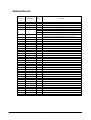
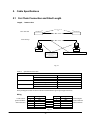
DT-X5 Series
Hardware Manual
(Version 1.04)
CASIO Computer Co., Ltd.
Copyright ©2006. All rights reserved.
September 2006
Table of Contents
Chapter 1
1.1
1.2
1.2.1
1.3
1.3.1
1.3.2
1.3.3
1.3.4
Chapter 2
2.1
2.1.1
2.1.2
2.2
2.3
2.4
2.5
2.6
2.7
2.8
Chapter 3
Chapter 4
4.1
4.1.1
4.1.2
4.1.3
4.1.4
4.1.5
4.2
4.2.1
4.2.2
4.2.3
4.2.4
4.2.5
4.3
4.3.1
4.3.2
4.3.3
4.3.4
4.4
4.4.1
4.4.2
4.4.3
4.5
4.5.1
4.5.2
4.5.3
Editorial Record
Preface
Overview
Features
Available Models and Options
Options and Interfaces
General Guide
HA-A34AT Car Mounted Battery Charger
HA-A61IO, HA-60IO Cradles
DT-5022CHG Dual Battery Charger
HA-A20BAT, DT-5025LBAT Battery Packs
Hardware Specifications
DT-X5
Reference for Laser Scanner Performance
Reference for C-MOS Imager Performance
HA-A61IO, HA-A61IO
HA-A34AT
HA-A30CHG
DIP Switch Setting for HA-A61IO
Status Indication with LEDs
DT-5022CHG
HA-A20BAT, DT-5025LBAT
Product Identification and Reference Numbers
Quality References
Environment Performances
DT-X5
HA-A61IO, HA-A30CHG
HA-A34AT
DT-5022CHG
HA-A20BAT, DT-5025LBAT
Electric Performances
DT-X5
HA-A61IO, HA-A30CHG
HA-A34AT
DT-5022CHG
HA-A20BAT, DT-5025LBAT
Mechanical Performances
DT-X5
HA-A61IO, HA-A30CHG
DT-5022CHG
HA-A20BAT, DT-5025LBAT
Reliability
DT-X5
HA-A61IO, HA-A30CHG
DT-5022CHG
Compliance
DT-X5
HA-A61IO, HA-A30CHG
AD-S42120AE
2
4
5
6
6
7
9
10
12
13
15
16
17
17
22
24
26
28
29
30
31
32
34
35
36
36
36
37
38
38
38
39
39
39
39
40
40
41
41
41
41
42
43
43
43
43
44
44
44
44
Chapter 5
5.1
5.2
Chapter 6
6.1
6.2
6.2.1
6.2.2
Cable Specifications
For Chain Connection and Short Length
For Chain Connection and Long Length
Precautions
Handling Precautions
Safety
Battery Pack
General
45
45
46
47
47
48
48
49
CASIO is a registered trademark of CASIO Computer Co., Ltd. in Japan.
Other product names or company names in this reference manual are either trademarks or registered trademarks of
their respective owners.
No part of this document may be produced or transmitted in any form or by any means, electronic or mechanical,
for any purpose, without the express written permission of CASIO Computer Co., Ltd. in Tokyo Japan.
Information in this document is subject to change without advance notice. CASIO Computer Co., Ltd. makes no
representations or warranties with respect to the contents or use of this manual and specifically disclaims any
express or implied warranties of merchantability or fitness for any particular purpose.
© 2006 CASIO Computer Co., Ltd. All rights reserved.
3
Editorial Record
Manual
Version
no.
0.90
1.00
1.01
1.02
1.03
March 2004
August 2004
September 2004
February 2005
August 2006
1.04
September 2006
Date edited
Page
36
all
7
9
32
7
Content
Tentative version
Original version
The content in Table 4.11 of Chapter 4 has been updated.
The description about C-MOS imager has been added.
The content in Table 1.2 of Chapter 1.2 is updated.
The content in Fig. 1.2 of Chapter 1.2.1 is corrected.
The content in Table 2.14 of Chapter 2.7 is updated.
The description about the phased out AC adaptors, MPC-577ADPE
and MPC-577ADPG, are added in Table 1.2 of Chapter 1.2.
4
Preface
A new industrial handheld terminal has been developed. CASIO introduces the DT-X5 series of handheld terminal
with built-in SH-3 (32-bit RISC type) Processor, high speed laser scanner and diverse wireless LAN
communications via Bluetooth as standard and IEEE802.11b WLAN (model dependent). Running under
Microsoft Windows CE .NET4.1 operating system, the rugged DT-X5 is designed specifically for industrial
applications.
This reference manual will explain about the hardware specifications and the details for the Laser integrated
models (DT-X5M10E, DT-X5M10R) and the C-MOS imager integrated models (DT-X5M30E, DT-X5M30R,
DT-X5M30U) and the dedicated options only.
For software and library related references, refer to the respective reference manuals released on the CASIO WEB
site at http://www.casio.co.jp/English/system/.
5
1. Overview
1.1 Features
Incorporates .NET technology
•
•
•
Uses WindowsCE .NET 4.1 operating system.
Makes effective use of .NET resources developed by other parties.
Employment of Embedded OS makes it possible to build a flexible WindowsCE system.
Enhanced communicating functions
•
•
•
•
Built in Bluetooth Ver 1.1 module.
The transfer rate of the Wireless LAN (model dependent) is 5 Mbps, which is the maximum rate of
communication for peer-to-peer connection with PC over IEEE802.11b.
The following protocol stacks are available for Bluetooth interface:
GAP (Generic Access Profile), SDP (Service Discovery Profile), SPS (Serial Port), Dialup Network, File
Transfer.
Security function (WEP 128 bits)
Superb reading capability
•
•
•
With the installed high speed laser scanner (DT-X5M10E, DT-X5M10R) it is possible to read any industrial
1D bar code symbologies.
Multi-step read function.
With the installed C-MOS imager (DT-X5M30E, DT-X5M30R, DT-X5M30U) it is possible to read the
most widely used 2D symbologies as well as the industrial standard1D symbologies.
Support of outstanding development environment
Ample Microsoft development tools provided for easy application development and an advanced debug
environment.
6
1.2 Available Models and Options
Table 1.1 Models of DT-X5 series
Wireless LAN
Model
IEEE802.11b Bluetooth
DT-X5M10E
No
Yes
DT-X5M10R
ETSI
Yes
DT-X5M30E
No
Yes
DT-X5M30R
ETSI
Yes
DT-X5M30U
No
Yes
IEEE802.11b
Bluetooth
C-MOS
Laser
Lithium-ion
Alkaline
Table 1.2 Options
Model
HA-A61IO
HA-A60IO
HA-A34AT
HA-A30CHG
DT-5022CHG
HA-A20BAT
DT-5025LBAT
AD-S42120AE
AD-S45150AU
AD-S45150AE
Scan Engine
Laser
C-MOS
Yes
No
Yes
No
No
Yes
No
Yes
No
Yes
Operating battery
Lithium-ion/ Alkaline
Lithium-ion
Lithium-ion/ Alkaline
Lithium-ion
Lithium-ion/ Alkaline
: WLAN module (compliant with IEEE802.11b) is integrated as standard.
: Bluetooth Version 1.1 module is integrated as standard
: Capable to scan 1D/2D symbologies and to capture images.
: Capable to scan 1D symbologies.
: Lithium-ion battery pack (HA-A20BAT or DT-5025LBAT only)
: AA-size alkaline battery (x 2 pcs)
Product
Bridge Satellite Cradle
Bridge Basic Cradle
Battery Charger Car Mount Unit
Cradle-type Battery Charger
Dual Battery Charger
Battery Pack
Large-capacity Battery Pack
AC Adaptor
AC Adaptor
AC Adaptor
Remark
1,700 mAH, 3.7V
3,400 mAH, 3.7V
Input range; 100 to 240 VAC
Input range; 100 to 230VAC. With US
power cord. For DT-5022CHG.
Input range; 100 to 230VAC, With
European and US power cords. For
DT-5022CHG.
See note.
MPC-577ADPE
AC Adaptor
MPC-577ADPG
DT-827CAC
Car Power Cable
DT-891WH
Wall Mount Unit
DT-887AXA
RS-232C cross cable
Cable length; 1.5 m, 9-pin male
DT-882RSC
RS-232C cross cable
25-pin male
DT-883RSC
RS-232C cross cable
25-pin female
DT-888RSC
RS-422 modular cable
Cable length; 1.0 m
DT-380USB
USB cable
Cable length; 2.0 m
Note:
MPC-577ADPE and MPC-577ADPG are phased out as of August 2006. The successor models are
AD-S45150AE and AD-S45150AG..
7
The accessories in the table below are accompanied as accessory in each individual carton box of DT-X5.
Table 1.3 Accessory
Product
Q’ty
Remark
AA size Alkaline battery
2
For DT-X5M10E, M30E and M30U only
Alkaline battery holder
1
For DT-X5M10E, M30E and M30U only
Wrist strap
1
Large-capacity battery pack cover
1
For DT-5025LBAT
Battery pack cover
1
For DT-X5M10E, M30E and M30U only
User’s guide
1
in English and Chinese
8
1.2.1 Options And Interfaces
DT-X5
IrDA Printer
( Recommended
Option)
USB
IrDA Ver. 1.1
Bridge Basic Cradle
HA-A60IO
PC
AC Adaptor
AD-S42120AE
Bridge Satellite
Cradle
HA-A61IO
Power Supply
Terminals
( Built-in Battery
Charge Circuit)
USB
RS-232C
RS-422
PC
RS-422
AC Adaptor
AD-S42120AE
Bridge Satellite
Cradle
HA-A61IO
AC Adaptor
AD-S42120AE
AC Adaptor
AD-S42120AE
Cradle-type Battery
Charger
HA-A30CHG
Battery Charger Car
Mount Unit
HA-A34AT
Car Power Cable
DT-827CAC
SS? ?
WLAN
?? ?
( IEEE802.11b)
Access-Point
(Recommended
Option)
Bluetooth Module
(Ver. 1.1 Class2)
Bluetooth Equipment
(Recommended
Option)
Battery Pack
HA-A20BAT
Battery Pack
HA-A20BAT
Large-capacity
Battery Pack
DT-5025LBAT
Large-capacity
Battery Pack
DT-5025LBAT
Dual Battery
Charger
DT-5022CHG
Fig. 1.2
9
Dual Battery
Charger
DT-5022CHG
AC Adaptor
AD-S45150AU
AD-S45150AE
1.3 General Guide
Views for DT-X5M10E, DT-X5M10R
Fig. 1.3
Note:
The front view in Fig. 1.3 is for all the models of DT-X5 series.
Views for side and back of DT-X5M30E, DT-X5M30U and DT-X5M30R
22
Fig. 1.4
Refer to Table 1.4 “Names of parts” in the following page for each part and its description.
10
Table 1.4 Names of parts
No.
Name
1
Indicator 1
2
Indicator 2
3
4
5
6
7
LCD panel
Power key
L key
R key
Cursor key
8
9
10
11
Multi key
Numeric keys
ENT key
Function keys
12
IR port
13
Power contacts
14
15
CLR key
Fn key
16
17
Battery pack cover
lock switches
R Trigger key
18
L Trigger key
19
20
21
Wrist strap hook
Reset switch
Battery pack cover
22
Bar code reader port
23
24
Buzzer
Maintenance
connector cover
Description
This indicator is green when charging is completed, and red during charging.
This indicator is green when the bar code has been read successfully, and red
when a reading error has occurred.
Displays text, operating instructions and so forth.
Switches the power on and off (press for about one second).
This is pressed to move the cursor to the left.
This is pressed to move the cursor to the right.
This functions in mainly the same manner as the cursor keys on a PC. It is
used when selecting items or scrolling the screen up and down and so on.
This can be set to perform arbitrary functions.
These are pressed to input numbers and letters.
This is pressed after entering a value or when advancing to the next step.
These keys can be assigned functions other than the functions for reading bar
codes. They are initially assigned the following default settings.
F1 : Deletes one characters to the left.
F2 : Inputs a hyphen (-).
F3 : Inputs a period (.).
F4 : Toggles to switch between numbers and alphabets (uppercase).
F5 : Inputs a space.
F6 : Functions similar to the Tab key on a PC. Used to move items for
input or selection.
F7 : Functions similar to the Tab key on a PC. Used to move items for
input or selection (but moves the opposite to F6.)
F8 : Not set.
This port is used for IR communication with another terminal or the Bridge
Satellite Cradle.
Contact points for supplying power from the Bridge Satellite Cradle and
Cradle-type Battery Charger.
This is pressed to clear the contents of all key inputs.
This is used to make various settings or start up preliminary registered
applications by pressing in combination with a function key or numeric key.
Fn and 1 keys
: Switches the backlight on and off.
Fn and 2 keys
: Darkens the contrast.
Fn and 3 keys
: Lightens the contrast.
Slide these switches when opening and closing the battery cover.
This key is used to read bar codes. It is also pressed when performing a full
reset.
This key is used to read bar codes. It is also pressed when canceling a full
reset.
This is used when attaching the wrist strap.
This is pressed to reset the terminal.
Covers the compartment that holds the battery pack or AA size alkaline
batteries.
Laser light is emitted from this port to read bar codes (Laser scanner
integrated models only).
LED lights are emitted from this port to read bar codes and stacked 2D codes
(C-MOS integrated models only).
Produces a buzzer tone.
This is used when performing maintenance and repairs. This cover should
normally not be opened.
11
1.3.1 HA-A34AT Battery Charger Car Mount Unit
View
Power Indicator Lamp
Power Contacts
HA-A30CHG
HA-A34AT
Power Switch
Car power code jack
Remove button
Fig. 1.5
Note:
The view in Fig. 1.5 shows HA-A34AT (Battery Charger Car Mount Unit) with HA-A30CHG (Cradle-type
Battery Charger) integrated to it.
12
1.3.2 HA-A61IO and HA-A60IO Cradles
Views
1
Top
2
3
Right
Front
Back
4
5
11
7
6
12 13
10
Bottom
8
9
Fig. 1.6
Refer to Table 1.5 “Names of parts” in the following page for each part name and its description.
13
14 15
Table 1.5 Names of parts
No.
Part Name
1
IR port
2
3
4
Terminal detect switch
Power contacts
Fall protector
5
Power indicator lamp
6
Communication
indicator lamp
7
System status indicator
lamp
8
Desktop unit
9
DIP switches
(HA-A61IO only)
Power switch
Wall mount unit
fastening plate
AC adaptor jack
RS-422 port
(HA-A61IO only)
RS-232C port
(HA-A61IO only)
10
11
12
13
14
15
USB port
Description
This port transfers data with the terminal IR port non-contact
communication.
This switch detects when the terminal is not seated correctly on the Cradle.
Power is supplied to the terminal via these contacts.
This is a removal attachment that prevents the terminal from tipping over
and falling.
This lamp indicates the mounting status of the terminal.
Off
: Power off
Green
: Power on, the terminal mounted correctly
Red
: Power on, the terminal not mounted
This lamp shows when the terminal is performing communication.
Off
: No communication being performed
Green flashing : Communication in progress
Red
: Problem with a connection between two Bridge Satellite
Cradles
This lamp indicates whether the system is operating normally. Regardless of
whether or not the terminal is mounted this lamp indicates the system status
and whether or not a communication operation with the system can be
performed.
Off
: System is not operating.
Green
: System is operating.
This is the base when using the Cradle in a desktop configuration. Remove
the desktop unit in the case of a wall mount configuration.
Use these switches to configure the Bridge Satellite Cradle as required.
Turns the power on and off.
The holes in this plate accept screws that secure the wall mount unit in place.
Connect the AC adaptor here sold separately to supply power.
This port is used when connecting to another Bridge Satellite Cradle.
This port accepts connection of an RS-232C cable for connection to a
computer for transfer of system data and file data. Use of the RS-232C port
requires installation of a special driver on the PC.
This port accepts connection of a USB cable for connection to a computer
for transfer of system data and file data. Use of the USB port requires
installation of a special driver on the PC.
14
1.3.3 DT-5022CHG Dual Battery Charger
Views
Charge status
indicators
Top
Battery pack compartments
Dual charger connection terminals
Right
Left
AC adaptor jack
Bottom
Connection attachments
Fig. 1.7
15
1.3.4 HA-A20BAT and DT-5025LBAT Battery Packs
Views
HA-A20BAT
Left
DT-5025LBAT
Top
Left
Side
Top
Side
Charge/Power supply
terminals
Charge/Power
supply terminals
Bottom
Bottom
Fig. 1.8
16
2. Hardware Specifications
2.1 DT-X5
Table 2.1
Item
CPU, Memory
CPU
Operating system
RAM
FROM (OS)
FROM (Storage)
Laser scanner
Method
Laser emitting window
Wave length
Output power
Scanning speed
Resolution
PCS
Depth
Readable width
Readable symbologies
Ambient light immunity
C-MOS imager
Method
Emitting window
Resolution
PCS
Depth
Readable width
Readable symbology
Display
Display device
No. of dots
Dot pitch
Scale
Display fonts
Backlight
Indicator
Confirmation /Status
Continue.
Specification
Remark
SH3 (32-bit RISC type)
Microsoft® Windows® CE .NET Ver. 4.1
16 MB (user area: approx. 7.5 MB)
32 MB
32 MB (user area: approx. 30 MB)
Semi-conductor laser
Redirected downward at 60 degrees
650±10 nm
Less than 1 mW
100±20 scans per second
0.127 mm
0.45 or more
0 (contact) to 400 mm
355 mm at 400 mm
See Chapter 2.1.1 on page 22.
See Table 2.3 on page 20.
Indoor 3,000 (fluorescent) Lux or less
Outdoor 80,000 Lux or less
300,000 pixels, monochrome
Redirected downward at 20 degree
1D: 0.15 mm
Stacked: 0.169 mm
1D: 0.45 or greater
Stacked 2D: 0.45 or greater
1D: 40 to 410 mm
Stacked 2D: 50 to 250 mm
240 mm at 410 mm
Stacked code symbologies.
Monochrome FSTN LCD
128 (w) x 160 (h)
0.3 (w) x 0.3 (h) mm
4 grades
Tahoma, Courier New, CA gothic,
Winding, MS gothic
LED
2 pcs x LED in red and green
17
See Chapter 2.1.2 on page 24.
See Table 2.4 on page 21.
Input
Keyboard
Control keys
Trigger keys
IrDA
Standard
Method
Synchronization
Baud rate
Comm. range
WLAN
Standard
Modulation
Frequency range
Baud rate
Comm. range
No. of channels
Output power
Other feature
Bluetooth
Standard
Comm. range
Output power
Wake-up function
Buzzer
Sound pressure
Vibrator
Cursor up-and-down key, L and R keys, Ten
keys (0 to 9), Fn key, Multi key, Function keys
(F1 to F8)
Power key, Reset switch
2 pcs (on the left and right sides)
IrDA Version 1.1
Half-duplex
Start/stop, frame synchronization
9600, 115200, 4 Mbps
0 (contact) to 0.3 m
IEEE802.11b
Direct sequence spread spectrum
2,400 to 2,483.5 MHz
11 Mbps (maximum)
150 m (outdoor), 50 m (indoor)
11 for FCC, 13 for ETSI
Minimum 12.5 dBm
Maximum 16.0 dBm
Roaming with multiple Access-Points
Bluetooth Version 1.1
Approx. 5 m
Maximum 3 dBm (PowerClass 2)
Available
“DSSS”
For DT-X5M10R, DT-X5M30R
Note 1
Note 1
75 dB or more
Available
Power
Operating battery
Lithium-ion battery pack x 1 pc or
AA-size alkaline battery x 2 pcs
Memory backup battery Lithium battery (rechargeable) on board
Battery life
See Table 2.2.
Battery capacity
HA-A20BAT: 1,700 mAH
DT-5025LBAT: 3,400 mAH
Backup period
Power with AA-size Alkaline battery
(Operating battery and
RAM: Approx. 120 days
memory backup
RTC : Approx. 145 days
battery)
Power with HA-A20BAT
RAM: Approx. 100 days
RTC : Approx. 125 days
Power with DT-5025LBAT
RAM: Approx. 175 days
RTC : Approx. 200 days
Continue.
18
See Table 2.2.
Conditions;
- Lithium-ion battery pack
(HA-A20BAT or
DT-5025LBAT) is fully
charged.
- AA-sized alkaline batteries
are brand new.
- The memory backup battery
is fully charged.
- The surrounding temperature
is room temperature.
Note 2
Lithium-ion battery
pack charge time
HA-A20BAT
DT-5025LBAT
Memory backup battery
charge time
Approx. 4 days
: Approx. 5 hours
: Approx. 10 hours
Conditions;
- The power switch is turned
off.
- The lithium-ion battery pack
is a brand new.
- The surrounding temperature
is at room temperature.
Conditions;
- Lithium-ion battery pack is
installed.
- The surrounding temperature is
at a room temperature.
Dimensions
Approx. 54 (W) x 179 (D) x 21.4 (H) mm
Note 4
Weight
Note 5
DT-X5M10E, M30E,
Approx. 245 g
M30U
DT-X5M10R, M30R
Approx. 250 g
Notes:
1. Concurrent use of WLAN communication and Bluetooth communication is not recommended.
2. Each memory backup period will depend on the characteristic of the terminal itself, the surroundings
including temperature, humidity. Thus, the periods described in Table 2.1 are recommended for use for
reference only. They are not guaranteed figures.
3. Backup for both data in RAM and the RTC (built-in clock) will commence when the battery pack (either
HA-A20BAT or DT-5025LBAT) runs down.
4. Any protruding part on the terminal is not measured.
5. Each weight includes the lithium-ion battery pack (HA-A20BAT) installed. The strap is excluded.
19
Table 2.2 Operating hours by model
Model
WLAN
IEEE802.11b
Scan
engine
DT-X5M10E
No
Laser
DT-X5M10R
DT-X5M30E,
DT-X5M30U
DT-X5M30R
Yes
No
Yes
Laser
C-MOS
C-MOS
Battery
Operating
hour
Alkaline batteries
HA-A20BAT
DT-5025LBAT
HA-A20BAT
DT-5025LBAT
HA-A20BAT
DT-5025LBAT
HA-A20BAT
DT-5025LBAT
Alkaline batteries
HA-A20BAT
DT-5025LBAT
HA-A20BAT
DT-5025LBAT
HA-A20BAT
DT-5025LBAT
HA-A20BAT
DT-5025LBAT
Approx. 200
Approx. 90
Approx. 180
Approx. 90
Approx. 180
Approx. 15
Approx. 30
Approx. 20
Approx. 40
Approx. 42
Approx. 40
Approx. 80
Approx. 40
Approx. 80
Approx. 15
Approx. 30
Approx. 20
Approx. 40
Operating mode
Scanning 2 times per 10
seconds.
Scanning 2 times per 10
seconds
Wait : RF : scan = 6.5:2:1.5
Wait: RF: scan: calculation =
20:1:1:1
Scanning 2 times per 10
seconds.
Scanning 2 times per 10
seconds.
Wait : RF : scan = 6.5:2:1.5
Wait: RF: scan: calculation =
20:1:1:1
Notes:
•
The durations of time in “Operating hour” for DT-X5M10R have been measured in the WLAN
configuration with Cisco Aironet 1100 Access-Point. These time durations may become different if other
Access-Point is employed.
•
The durations of time in “Operating hour” are measured under the conditions that new battery pack (or new
alkaline batteries) is used, the surrounding temperature is at 25 ºC and the dedicated test program is used.
•
In the low temperature, the operating hour powered by battery tends to be shorter.
Table 2.3 Readable 1D bar code symbologies
Symbology
EAN8/JAN8
EAN13/JAN13
UPCA
UPCE
Code39
Codabar (NW7)
Interleaved 2of5 (ITF)
Code93
Code128
MSI (Plessey)
IATA
Code11
RSS-14
RSS Limited
RSS Expanded
ISBT
Industrial2of5 (IDF)
Output format/Append function
2-digit/5-digit addon
2-digit/5-digit addon
NS output
2-digit/5-digit addon
NS output
UPCA conversion
2-digit/5-digit addon
Start/stop output
ASCII conversion
Start/stop bit output
Code sets A/B
Code set C
Standard/Truncated
Standard
20
C-MOS
imager
Yes
Yes
Yes
Laser
scanner
Yes
Yes
Yes
Yes
Yes
Yes
Yes
Yes
Yes
Yes
Yes
Yes
Yes
Yes
Yes
Yes
Yes
Yes
Yes
No
Yes
Yes
Yes
Yes
Yes
Yes
Yes
No
Yes
Yes
Yes
No
Yes
Table 2.4 Readable 2D stacked code symbologies
Symbology
Code49
PDF417
MicroPDF
Codablock F
EAN8/13 Composite
RSS Composite
UCC/EAN128
Composite
TLC39
RSS-14 (Stacked type)
RSS Expanded (Stacked type)
Output format/Append function
Stacked/
Stacked Omnidirectional
Stacked
21
C-MOS
imager
Yes
Yes
Yes
Yes
Yes
Yes
Yes
Laser
scanner
No
No
No
No
No
No
No
Yes
Yes
No
No
Yes
No
2.1.1 Reference for Laser Scanner Performance
Reference of the laser scanner performances below for the DT-X5M10E/DT-X5M10R is provided as a guide to be
utilized by the user. The user can refer to these reference values in the table for his or her specific business
application. All the reference values have been came out from the assessment tests carried out under the basic
performance conditions below. However, it does not necessarily imply that the values are guaranteed and optimum
to any kind of business applications. They are intended for use by the user as a reference only.
Table 2.5
Symbology
Specification
Remark
Depth
Read angles
Pitch
Skew
Dead-zone
Tilt
Curb
Code39
0.127 mm
0.15 mm
0.25 mm
0.33 mm
0.5 mm
1.0 mm
0 to 50 mm
0 to 60 mm
0 to 150 mm
0 to 200 mm
0 to 300 mm
0 to 400 mm
Code39
Code39
Code39
Jan 13 digits
0.25 mm
0.25 mm
0.25 mm
0.26 mm
±40 degree
±60 degree
±8 degree
±35 degree
JAN 8 digits
JAN 13 digits
0.26 mm
0.26 mm
R≥15 mm
R≥20 mm
Skew and pitch direction
PCS
0.45 or more
Ambient light immunity
Sunlight
Laser beam swing angle
Code39
Scanning width
80,000 Lux or less
0.25 mm
44 degree
60 mm
355 mm
Basic scanning conditions:
Test chart
PCS
Depth
Pitch angle
Skew angle
Tilt angle
Surrounding temperature
Surrounding illumination
Background of the bar code
: Dedicated test pattern
: 0.9 or greater
: 80 mm from the laser emission port
: 0 degree
: 15 degree
: 0 degree
: 25°C
: 500 to 900 Lux.
: Black
22
At contact
At 400 mm depth
0 to50
0 to 60
Resolution
0.25
0.33
0.5
1.0
0 to 150
0 to 200
0 to 300
0 to 400
Fig. 2.1
23
355
44
280
205
168
100
93
60
(Unit: mm)
2.1.2 Reference for C-MOS Imager Performance
Reference of the C-MOS imager performances below for the DT-X5M30E, DT-X5M30R and DT-X5M30U is
provided as a guide to be utilized by the user. The user can refer to these reference values in the table for his or her
specific business application. All the reference values have been came out from the assessment tests carried out
under the basic performance conditions below. However, it does not necessarily imply that the values are
guaranteed and optimum to any kind of business applications. They are intended for use by the user as a reference
only.
Table 2.6
1D/2D
1D
2D
(Stacked)
Angle
Pitch
Skew
Dead
zone
Tilt
Symbology
Code39
UPC
PDF417
Resolution
6 mil (0.15 mm)
8 mil (0.20 mm)
10 mil (0.254 mm)
13 mil (0.33 mm)
15 mil (0.38 mm)
20 mil (0.5 mm)
40 mil (1.0 mm)
13 mil (0.33 mm)
6.6 mil (0.168 mm)
8 mil (0.20 mm)
10 mil (0.254 mm)
15 mil (0.38 mm)
20 mil (0.5 mm)
Liner (Code39 10 mil (0.25 mm))
Stacked (PDF417 10 mil (0.25 mm))
Liner (Code39 10 mil (0.25mm))
Stacked (PDF417 10 mil(0.25 mm))
Pitch/Skew
Liner (Code39 10 mil (0.25 mm))
Stacked (PDF417 10 mil (0.25 mm))
Range (mm)
70 to 195
60 to 135
50 to 165
60 to 200
40 to 210
70 to 260
90 to 410
60 to 200
60 to 115
60 to 135
50 to 165
70 to 210
80 to 250
±35°
±35°
±40°
±40°
±5°(Pitch,
Skew)
360°
360°
PCS
Liner (Code39 10 mil (0.25 mm))
Stacked (PDF417 10 mil (0.25 mm))
Surrounding illumination
100 to 100,000 Lux.
Visible angle
V_Angle = 26° H_Angle = 35°
Operating temperature (Image sensor)
High temperature 50 ºC
Low temperature -10 ºC
0.45 or greater
0.45 or greater
24
A: Maximum
(close)
12
5
5
5
2
2
2
11
97
95
100
52
50
No. of read digits
B:
Recommended
12
12
10
10
8
8
5
11
100
100
100
50
50
C:
Maximum
21
22
20
19
17
16
12
11
1000
1000
1000
1000
1000
Remark
ECL4
ECL4
ECL4
ECL4
ECL4
At 110 mm from the LED emission port.
At 110 mm from the LED emission port.
At 110 mm from the LED emission port.
At 110 mm from the LED emission port.
At 110 mm from the LED emission port.
At 110 mm from the LED emission port.
At 110 mm from the LED emission port.
Basic scanning conditions:
Test chart
Resolution
PCS
Read judgment
Depth
Pitch angle
Skew angle
Tilt angle
Surrounding temperature
Surrounding humidity
Surrounding illumination
Background of the symbol
Conditional Judgment
: Dedicated test pattern (1D, 2D Stacked)
: 1D 0.25 mm / 2D 0.5 mm
: 0.9 or greater
: 7 times per 10 scans First Decode
: 110 mm from the LED emission port
: α = 0 degree
: β = 10 degree
: γ = 0 degree
: 25 ºC
: 30 to 50%
: 450 to 550 Lux.
: White
: Readable 7 times or more per 10 scanning
Far
20 mm or more
C: Max. readable digits
50 mm or more
B: Recommended readable digits
Readable range
Near
A: Max. readable digits (in close)
L
R
F
n
1 2 3
4 5 6
7 8 9
0
CLR
F1
F2
F3
F4
F5
F6
F7
F8
25
Fig. 2.2
2.2 HA-A60IO, HA-A61IO
Table. 2.7
Item
USB
11
1
22
2
4
4
3
Connector
1. VBus
2. –Data (D-)
3. +Data (D+)
4. GND
3
USB connector type B
Full duplex
Start/stop method
115.2 Kbps
Comm. method
Synchronization
Comm. speed
Applicable to
HA-61IO only.
SG ER SD RD CD
RS-232C
S E S R C
5 4 3 2 1
9 8 7 6
CI
C CSC RS
R DD
D-Sub 9-pin (Male)
Full duplex
Start/stop method
115.2 Kbps
IN
OUT
No. of LEDs
Status LED
No. of display colors
Display content
Input
DIP switch (HA-A61IO only)
Detection switch for DT-X5
Input voltage
Input from AC
adaptor
Power
Charge/supply
power
Consumption current
Plug
AC adaptor
Output voltage
Output current
Charge method
Charge time
Continue.
26
66 55 44 33 22 11
RSI+
RSO+
RSO-
SDO-
SDO+
RDI-
Connector
RDI+
66 55 4 4 3 3 2 2 1 1
RSI-
RS-422
Applicable to
HA-A61IO only.
SDI+
Comm. method
Synchronization
Comm. speed
SDI-
Connector
Display
Remark
RD0-
IrDA
Specification
IrDA Ver. 1.1 compatible
Half duplex
Start/stop method
4 Mbps (maximum)
USB Ver. 1.1 compatible
12 Mbps (maximum)
Standard
Comm. method
Synchronization
Comm. speed
Standard
Comm. speed
RDO+
Interface
RJ-45 compatible (6 pins)
3 (HA-A61IO)
2 (HA-A60IO)
2 (red, green)
System operation status (“LINE”) Refer to Chapter 2.6
Comm. status (“DATA”)
“Status Indication
Power status (“POWER”)
With LEDs”.
8 switches
See page 30.
Push switch
DC 12V±5%
DC12V Approx. 3.5A
While supplying
power or transmitting
data.
EIAJ RC-5320A Class 4
Center pin: plus
AD-S42120AE
DC 5V±10%
1,500 mA (maximum)
Constant voltage
With curb function on
current
Approx. 4.0 hours
For HA-A20BAT
Approx. 8.0 hours
For DT-5025LBAT
Power contact
Power contact
GND
The illustration of
the power contact
on the left is viewed
at the front of the
cradle.
Weight/Dimensions
Table 2.8
Model no.
Configuration
In desktop state
In wall mount state
Dimensions In desktop state
In wall mount state
Weight
In desktop state
In wall mount state
Dimensions In desktop state
In wall mount state
Weight
HA-A61IO
HA-A60IO
27
Specification
Approx. 530 g
Approx. 620 g
Approx. 110 (W) x 125 (D) x 128 (H) mm
Approx. 110 (W) x 148 (D) x 153 (H) mm
Approx. 520 g
Approx. 610 g
Approx. 110 (W) x 125 (D) x 128 (H) mm
Approx. 110 (W) x 148 (D) x 153 (H) mm
2.3 HA-A34AT
Table 2.9
Item
Display
Input
Power
Specification
Remark
No. of LEDs
1
No. of display colors
2
In red and green
Display content
Power status (“POWER”)
Status LED
Indicates the status of terminal being mounted on the charger.
OFF
: Power is off.
Flashing in green : Power is on and the terminal is mounted on the charger.
Flashing in red
: Power is on but the terminal is not mounted on the charger.
Detection switch for the terminal
Push switch
Input voltage
DC 12V/24V±5%
While supplying
DC 12V : Approx. 1,400 mA
Input from AC Consumption current
power.
DC 24V : Approx. 700 mA
adaptor
Plug
EIAJ RC-5320A Class 4
Center: plus
Power cord
DT-827CAC
Output voltage
DC 5V±10%
Output current
2,500 mA (maximum)
Charge method
Constant voltage
With curb function
on current
Approx. 4.0 hours
For HA-A20BAT
Charge time
Approx. 8.0 hours
For DT-5025LBAT
Charge/supply
The illustration of
power
the power supply
terminals on the left
Power supply terminals
is viewed at the
Power supply
GND
front of the charger.
terminals
Weight/Dimensions
Table 2.10
Weight
Dimensions
Specification
Approx. 840 g
Approx. 111 (W) x 243 (D) x 104 (H) mm
28
Remark
When configured with HA-A30CHG.
When configured with HA-A30CHG.
2.4 HA-A30CHG
Table 2.11
Item
Display
Input
Power
No. of LEDs
Status LED
No. of display colors
Display content
Detection switch for DT-X5
Input voltage
Consumption current
Input from AC
adaptor
Plug
AC adaptor
Output voltage
Output current
Charge method
Charge/Power
supply
Specification
1
2
Power status (“POWER”)
Push switch
DC 12V±5%
Approx. 3.5A
EIAJ RC-5320A Class 4
AD-S42120AE
DC5V±10%
1,500 mA (maximum)
Constant voltage
Approx. 4 hours
Approx. 8 hours
Charge time
Power contact
Power contact
GND
Remark
In red and green
While supplying
power or
transmitting data.
Center: plus
With current curb
function
For HA-A20BAT
For DT-5025LBAT
The illustration of
the power contact on
the left is viewed at
the front of the
charger.
Weight/Dimensions
Table 2.12
Configuration
Specification
In desktop
Approx. 510 g
configuration
Weight
In wall-mount
Approx. 600 g
configuration
In desktop
Approx. 110 (W) x 125 (D) x 128 (H) mm
configuration
Dimensions
In wall-mount
Approx. 110 (W) x 148 (D) x 153 (H) mm
configuration
Note:
The dimensions include the DT-891WH Wall Mount Unit attached to HA-A30CHG.
29
Remark
See note.
2.5 DIP Switch Setting for HA-A61IO
The DIP switch is located on the rear side of the Bridge Satellite Cradle. Change the ON/OFF settings according to
your required system configuration. The new settings do not go into effect until the power switch is turned off and
then back on again.
ON(Upper side)
OFF(Lower side)
Not used (Always set to "OFF")
Not used (Always set to "OFF")
Host computer interface
Interface
RS-232C
USB *
6
OFF
ON
Termination setting for daisy chain connection
Termination
5
At middle
OFF
No chain/Termination*
ON
Connection mode
Mode
With Host PC*
Chain connection
3
OFF
ON
4
OFF
OFF
Communication speed between Cradles
Baud rate
1
115,200bps *
ON
2
OFF
* : Default setting.
Fig. 2.3
Note:
Other DIP switch settings are used for testing and inspection purposes. Because of this, you should never use any
DIP settings other than those described above.
30
2.6 Status Indications with LEDs
Various operational statuses on the HA-A61IO can be displayed using the LEDs. The following table describes
LED modes and their meanings.
Table 2.13
Item
LED
Power status indicator
(POWER)
Comm. status indicator
(DATA)
(HA-A61IO only)
Line status indicator
(LINE)
Specification
Power off.
Power is on and the terminal is mounted correctly.
Power is on but the terminal is not mounted
correctly.
No communication being performed.
Communication is in progress.
Problem with a connection between two Bridge
Satellite Cradles.
System is not operating.
System is operating.
31
Remark
Off
Green
Red
2-color LED
Off
Green
Red
2-color LED
Off
Green
2-color LED
2.7 DT-5022CHG
Basic Block
Table 2.14
Item
Basic function
Rechargeable battery pack
HA-A20BAT
DT-5025LBAT
AC adaptor
AD-S45150AU
AD-S45150AE
Specification
Remark
Battery pack (1,700 mAH)
Large-capacity size battery pack (3,400 mAH)
Dedicated batteries only.
Input; 100 to 230VAC
Input; 100 to 230VAC
With US power cord
With European power cord
Interface Block
Table 2.15
Item
Input terminals for joint block
1: VIN2
2: VIN3
3: NC
4: GND
Output terminals for joint block
1: VOUT1
Specification
Rated DC16V Input voltage 8 to 20V
Rated DC16V Input voltage 8 to 20V
NC
GND
2: VOUT2
3: NC
4: GND
No. of joint-able units
DC16V
NC
GND
3 units (x DT-5022CHG)
DC16V
Remark
Output terminal from 1st unit when AC
adaptor is used.
Output terminal from 2nd unit
Power Supply Block
Table 2.16
Item
Specification
Remark
Input
Rated voltage
DC 16V
Input voltage
DC 8.0 to 20V
Rated output
Rated output voltage
DC 4.22V
Rated output current
DC 1,600 mA
Input consumption current
Input consumption current
0.65 A
When input voltage is at 16V.
Charge output terminal CH1
PIN1: +
4.22V±30mV
PIN2: GND
Charge output terminal CH2
PIN1: +
4.22V±30mV
PIN2: GND
Input terminal
DC jack
Rated DC16V, input voltage DC 8.0 to 20.0V
32
Battery Charge Block
Table 2.17
Item
Specification
Charge control
Output voltage
DC4.22V±30mV
Charge current (standard mode)
DC1,600mA±10%
Charge current (standby mode)
DC160±40mA
Full charge detection current
DC120±30mA
Voltage control
Full charge detection voltage 4.1V
Re-charge detection voltage 4.0V
Re-charge detection voltage
DC4.0±0.1V
Input voltage
DC8.0 to 20V
Timer
Charge timer (standby mode)
90 minutes
Charge timer (standard mode)
720 minutes
Trickle charge timer
120 minutes
Charge hour
HA-A20BAT
Approx. 2.5 hours (for 1 pack)
Approx. 5.0 hours (for 2 packs at same time)
DT-5025LBAT
Approx. 5.0 hours (for 1 pack)
Approx. 10.0 hours (for 2 packs at same time)
Temperature control
Not available
No. of charge outputs
1
Operation mode
Battery pack mount detection
Battery pack not mounted
LED OFF, charge output OFF
Battery pack mounted
LED ON in red, charge output OFF
Check on battery pack
LED ON in red, charge output OFF
Battery charge (standby mode)
LED ON in red, charge output ON
Battery charge (standard mode)
LED ON in red, charge output ON
Wait mode in trickle charge
LED ON in green, charge output OFF
Charge in trickle mode
LED ON in green, charge output ON
Charge completed
LED ON in green, charge output OFF
Charge abnormal end
LED flash in red, charge output OFF
Other
Priority order of battery charging
Order in mounted order
Remark
At 0 to 40 ºC
At 0 to 40 ºC
Weight/Dimensions
Table 2.18
Item
Weight
Dimensions
Specification
Approx. 154 g
100 (L) x 110 (W) x 49 (H) mm
33
Remark
2.8 HA-A20BAT, DT-5025LBAT
Table 2.19
Item
Rated capacity
Rated voltage
Discharge end voltage
Standard charge current
Charge voltage
Charge hour
(standard mode)
Weight
Dimensions
Specification
HA-A20BAT
1,700 mAH
3.7V
2.75V
1.0 CA (=1.55A)
0 to 40 °C
4.2±0.05V
2.5 hours
DT-5025LBAT
3,400 mAH
3.7V
2.75V
1.6A
0 to 50 °C
4.2±0.05V
5.0 hours
Approx. 45 g
57 (L) x 37 (W) x 13 (H) mm
Approx. 87g
57 (L) x 37 (W) x 24 (H) mm
34
Remark
0.2C discharge
0.2C discharge
Charge on
DT-5022CHG
3. Product Identification and Reference Numbers
On the back of the terminal and its options (major options only), there is a bar code and numbers printed on label as
shown in Fig. 3.1 below.
This bar code is represented by 15 digits of Code128 and by alphanumeric characters beneath the bar code. The
numbers from 1 to 9 in the figure represent identification and references of the terminal. The numbers from 10 to
14 represent a manufacturing reference which is reserved by the manufacturer. See the figure below for each
meaning.
1
2
3
4
5
6
7
8
9
10
Serial number of the
terminal in 5 digits
11
12
13
Manufacturing references
(reserved by the
manufacturer)
Production month of the year (1 to 9, A,B,C)
Production year (last digit only. Ex. 1 represents the year 2001.)
Model number (two digits in alphanumeric)
81: DT-X5 (Domestic version)
82: DT-X5 (Domestic version)
83: DT-X5M10E
84: DT-X5M10R
86: DT-X5M30E
87: DT-X5M30U
88: DT-X5M30R
72: HA-A61IO
73: HA-A60IO
Fig. 3.1
35
14
15
Check digit
4. Quality References
This chapter describes about references of the DT-X5 and its dedicated options concerned with environmental
performance, compliance, mechanical and electric durability, etc.
4.1 Environmental Performances
4.1.1 DT-X5
Table 4.1
Item
Specification
Condition
Temperature
Operation
-20 ºC to 50 ºC
Non-operation
-20 ºC to 70 ºC
0 to 40 ºC while mounting
on Cradle.
Humidity
Operation
Non-operation
Storage in carton box
Temperature
Humidity
Dust and water-splash proof
10 % to 80 %RH
5% to 90 %RH
No condensation
No condensation
-20 ºC to 60 ºC
90 %RH or less
IP54 level (compliant with IEC60529)
See “IP (Industrial Protection) code”.
All covers on the terminal
are closed while testing.
IP (Industrial Protection) code
A cording system to indicate the degrees of protection provided by an enclosure against access to hazardous parts,
ingress of solid foreign objects, ingress of water and to give additional protection in connection with such
protection. Elements of the IP54 level and their meanings are as follows.
IP5x
Represents dust proof to level 5. This level of IP code means that the terminal is protected against solid foreign
objects including dust to penetrate the enclosure.
IPx4
Represents water-splash proof to level 4. No detrimental effect is observed even with exposure to water splashed
from any direction.
36
4.1.2 HA-A60IO, HA-A61IO, HA-A30CHG
Table 4.2
Item
Specification
Temperature
Operation
Storage
0 ºC to 40 ºC
-10 ºC to 50 ºC
Humidity
Operation
Storage
Storage in carton box
Temperature
Humidity
Dust and water-splash proof
30% to 80%RH (No condensation)
30% to 90%RH (No condensation)
-10 ºC to 50 ºC
30% to 90%RH
Not applicable.
37
Condition
4.1.3 HA-A34AT
Table 4.3
Item
Specification
Condition
Temperature
Operation
Storage
0 ºC to 40 ºC
-40 ºC to 85 ºC
Humidity
Operation
Storage
Storage in carton box
Temperature
Humidity
30% to 80%RH (No condensation)
30% to 95%RH (No condensation)
-10 ºC to 50 ºC
30% to 90%RH
4.1.4 DT-5022CHG
Table 4.4
Item
Specification
Condition
Temperature
Operation
Non-operation
Storage
0 to 40 ºC
-10 to 50 ºC
-10 to 55 ºC
When battery is not charged.
With carton box
Operation
Storage
20 % to 90 %RH (no condensation)
20 % to 90 %RH (no condensation)
With carton box
Humidity
4.1.5 HA-A20BAT, DT-5025LBAT
Table 4.5
Item
Specification
Condition
Temperature
Operation
Non-operation
Storage
0 to 40 ºC
-5 to 50 ºC
-10 to 55 ºC
When battery is not charged.
With carton box
Operation
Storage
20 % to 90 %RH (no condensation)
20 % to 90 %RH (no condensation)
With carton box
Humidity
38
4.2 Electrical Performances
4.2.1 DT-X5
Table 4.6
Item
Power consumption
Anti-static strength
Malfunction
Destruction
Specification
DC1.1A/3.0V to 5V
DC1.3A/3.0V to 5V
DC1.4A/3.7V to 5V
DC1.6A/3.7V to 5V
Remark
For DT-X5M10E
For DT-X5M30E/DT-X5M30U
For DT-X5M10R
For DT-X5M30R
±4 KV (contact), ±8 KV (in air)
±12 KV
Compliant with EN6100-4-2
4.2.2 HA-A60IO, HA-A61IO, HA-A30CHG
Table 4.7
Item
Current
consumption
Input voltage
Specification
Approx. 0.02 A/DC12V (HA-A60IO)
Approx. 0.15 A/DC12V (HA-A61IO)
Approx. 0.02 A/DC12V (HA-A30CHG)
Approx. 0.9 A/DC12V (HA-A60IO)
Approx. 1.0 A/DC12V (HA-A61IO)
Approx. 0.9 A/DC12V (HA-A30CHG)
DC12V±5% (HA-A60IO)
DC12V±5% (HA-A61IO)
DC12 or 24V±5% (HA-A30CHG)
Anti-static strength
Malfunction
Destruction
Line noise strength
(Malfunction)
±6 KV
±12 KV
1,000 V
Power interruption
10 milliseconds or less
Remark
When the terminal is not mounted on.
While supplying power, or transmitting data.
DC24V for HA-A30CHG is only when HA-A34AT
Battery Charger Car Mount Unit is attached to it.
150 pF, 330 ohm
Pulse width: 5 KHz
Burst cycle: 300 milliseconds
No. of pulses: 75 pcs
Burst period: 15 milliseconds
4.2.3 HA-A34AT
Table 4.8
Item
Consumption
current
Voltage
Anti-static strength
Malfunction
Destruction
Specification
DC 12V : Approx. 1,400 mA
DC 24V : Approx. 700 mA
DC 12V/24V±5%
±6 KV
±12 KV
Remark
While supplying power.
150 pF, 330 ohm
39
4.2.4 DT-5022CHG
Table 4.9
Item
Anti-static strength
Malfunction
Destruction
Specification
±5 KV
±10 KV
Remark
ESD method: 250 pF, 100 ohm
Probe: Finger type
Polarity: ±
4.2.5 HA-A20BAT, DT-5025LBAT
Table 4.10
Item
Anti-static strength
Malfunction
Destruction
Specification
±5 KV
±10 KV
40
Remark
ESD method: 250 pF, 100 ohm
Probe: Finger type
Polarity: ±
4.3 Mechanical Performances
4.3.1 DT-X5
Table 4.11
Item
Specification
Resistance to drop impact (height)
In bare condition
180 cm
In individual carton box 70 cm or less
In master carton box
70 cm or less
Resistance to vibration
1.5 G or less
Condition
Onto concrete, one time on each of the 6 sides and 4
corners.
Onto concrete, one time on each of the 6 sides, 1
corner, 3 edges.
10 to 55 Hz
In X,Y, and Z directions
Reciprocally for 30 minutes
4.3.2 HA-A60IO, HA-A61IO, HA-A30CHG
Table 4.12
Item
Resistance to vibration
Specification
1.5 G or less
Resistance to vibration
(in package)
1.5 G or less
Resistance to impact
In bare condition
In individual carton box
In master carton box
70 cm
70 cm or less
50 cm or less
Condition
10 to 55 Hz
In X,Y, and Z directions
Reciprocally for 30 minutes
10 to 55 Hz
In X,Y, and Z directions
Reciprocally for 30 minutes
One time for 6 faces onto concrete surface
One time for 6 faces, 1 corner and 3 edges
4.3.3 DT-5022CHG
Table 4.13
Item
Resistance to vibration
Specification
1 G or less
Resistance to vibration
(in package)
2 G or less
Resistance to impact
In bare condition
In individual carton box
75 cm
75 cm or less
41
Condition
10 to 55 Hz
In X,Y, and Z directions
Reciprocally for 30 minutes
10 to 55 Hz
In X,Y, and Z directions
Reciprocally for 15 minutes
6 faces, 1 corner and 3 edges
6 faces, 1 corner and 3 edges
4.3.4 HA-A20BAT, DT-5025LBAT
Table 4.14
Item
Resistance to vibration
Specification
1.5 G or less
Condition
10 to 55 Hz
In X,Y, and Z directions
Reciprocally for 30 minutes
Resistance to impact
In bare condition
In individual carton box
100 cm
70 cm or less
6 faces, 4 edges onto P-tile.
6 faces, 3 edges, 1 corner onto P-tile.
42
4.4 Reliability
4.4.1 DT-X5
Table 4.15
Item
Specification
Remark/Condition
Service life
Backlight
10,000 hours
At half-life period
Laser scanner
10,000 hours
C-MOS imager
70,000 hours
Trigger keys
1,000,000 times
For each trigger key
Other keys
500,000 times
Mounting/removing of the
10,000 times
terminal to/from the Cradle
MTBF
62,413 hours
Electronic parts only
MTBF (WLAN module)
27,000 hours
Charging and discharging cycle of 300 times or more
Applicable to HA-A20BAT and
battery pack
DT-5025LBAT (see notes)
Note:
The number of the cycles is assumed with the conditions below.
• The remained capacity of battery pack at the 300 cycles is approximately 58% of the full capacity.
• The surrounding temperature is 20 ºC.
• The discharge current is 1.6A constant current.
4.4.2 HA-A60IO, HA-A61IO, HA-A30CHG
Table 4.16
Item
MTBF for electronics parts
Mounting/removing the terminal to/from Cradle
Power switch
Switch
DIP switch
USB
No. of ON/OFF times of the
RS-232C
connector
RS-422
No. of ON/OFF times of the power jack
Specification
50,000 hours
20,000 times
5,000 times
10 times
500 times
500 times
100 times
1,500 times
Remark/Condition
For HA-A61IO only
For HA-A61IO only
For HA-A61IO only
4.4.3 DT-5022CHG
Table 4.17
Item
MTBF
Protection from short
Specification
210,000 hours or more
Internal circuit is protected from a short between
the charge terminals
43
Remark
MIL-HDBK217F
4.5 Compliance
4.5.1 DT-X5
EMC, EMI, Safety, WLAN /Bluetooth type approvals
Table 4.18
Model
EN301.489-17
(EMI,EMS)
Compliance Standard
Europe
EN60825
EN300.328-2
(Laser)
(Bluetooth,
WLAN)
EN60950
(Safety)
DT-X5M10E
Yes
DT-X5M10R
Yes
DT-X5M30E
Yes
DT-X5M30R
Yes
Columns in gray color: not applicable.
Yes
Yes
Yes
Yes
Yes
Yes
Yes
Yes
Yes
Yes
Yes
Yes
EN50371
EN50361
EN50360
(SAR)
Yes
Yes
Yes
Yes
Table 4.19
Model
DT-X5M30U
Compliance Standard
USA
FCC
UL60950-1
FCC Part 15
Part 15B Class
sub part C +
B
SAR
Yes
Yes
Yes
4.5.2 HA-A60IO, HA-A61IO, HA-A30CHG
Table 4.20
EMC
Safety
Compliance Standard
Europe
USA
EN55022:1998+A1:2000 Class B
FCC Part 15B Class B
EN55024:1998+A1:2001 Class B
EN60950
UL60950 3 Edition: 2000
4.5.3 AD-S42120AE, AD-S45150AU, AD-S45150AE
Table 4.21
Compliance Standard
Safety
Europe
EN60950 (1991) 2nd edition
44
USA
UL1950 3 Edition
5. Cable Specifications
5.1 For Chain Connection and Short Length
Length; 1 meter or less
M a x m im u m
1m
View from side
View from top
1 2 3 4 5 6
1 2 3 4 5 6
C a b le ( s e e T a b le 5 . 1 )
M o d u la r p l u g
( c o m p p a t i b le w it h
6 /6 -6 F R S Y K (S a b y o
In d u s tr ia l)
Fig. 5.1
Table 5.1 Specifications of the cable
Cable
Core wire
Conductor
Insulator
Finish of external shape
Insulator
Finish of external shape
Conductance resistance
Insulation resistance
Sheath
Characteristics
20/0.1A
Semi-hard material P.V.C.
20/0.1A
P.V.C.
φ4.3±0.1mm
0.12ohm /m or less
50Mohm or more
Pin layout diagram of cable for chain connection and short distance (pin-to-pin straight connection)
Wiring
Cradle at lower
position under the
chain connection
Pin no.
1
2
3
4
5
6
Signal
IRS+
IRSISD+
ISDORD+
ORD-
Pin no.
1
2
3
4
5
6
Fig. 5.2
45
Signal
ORS+
ORSOSD+
OSDIRD+
IRD-
Cradle at higher
position under the
chain connection
5.2 For Chain Connection and Long Length
Length; 1 meter or longer
View from side
Max. 1,000m
View from top
123456
123456
Modular plug compatible
with 6/6-6 FR SYK50 by
Sanyo Industrial Co.
Cable compatible with SK-UTP
100M3P by Sanyo Industrial Co.
Fig. 5.3
Pin layout diagram of cable for chain connection and long distance (pin-to-pin straight/twist-pair connection)
Wiring
Cradle at lower
position under the
chain connection
Pin no.
1
2
3
4
5
6
Signal
IRS+
IRSISD+
ISDORD+
ORD-
XXXXXX
XXXXXX
XXXXXX
Fig. 5.4
46
Pin no.
1
2
3
4
5
6
Signal
ORS+
ORSOSD+
OSDIRD+
IRD-
Cradle at higher
position under the
chain connection
6. Precautions
6.1 Handling Precautions
Precautions for short-term storage (1 to 2 days)
•
•
If the DT-X5 is to be stored over holidays (including Saturday and Sunday), replace the battery pack (or
AA-size alkaline batteries) with brand-new one before starting the holiday. This will conserve the built-in
memory backup battery and ensure retention of data on the terminal.
If there is a possibility of the above or operator error (e.g., a fully charged battery has not been inserted),
practice system operation that maintains a backup to avoid loss of data due to consumption of the batteries.
Precautions for long-term storage (over one week)
•
•
Prior to long-term storage (over one week), always back-up data in the terminal to other memory storage
device. In addition, remove the lithium-ion battery pack or AA-size alkaline batteries before storage. This can
minimize overly discharging the installed battery and minimize consumption of the memory backup battery.
Do not store the removed battery pack or AA-size alkaline batteries at high temperature. Otherwise, it will
discharge at an accelerated rate. Note that the capacity after the battery if it is not used for 10 days at 60°C
will be 65%, and that after 20 days at 60°C will be 55%.
47
6.2 Safety
6.2.1 Battery Pack
•
•
•
•
•
•
•
•
•
•
•
•
•
•
Never disassemble or retrofit the battery pack. The battery pack has safety mechanism and protection means
incorporated to avoid hazards. Should they be damaged, the battery pack could become hot, generate smoke,
explode, or ignite.
Never contact the “+” and “-“ terminals with metal objects such as a wire. Also, do not carry or store the
battery with a metal necklace or hair pin. Otherwise, the battery pack may be short-circuited resulting in an
excessive current and causing the battery to become hot, smoke, explode, or catch fire.
Neither dispose of the battery pack into a fire nor heat it. The insulation may be burnt, the gas exhaust valve
or safety mechanism may be damaged, or the internal electrolyte may ignite, causing the battery pack to
become hot, smoke, explode, or ignite.
Neither leave nor use the battery pack in a place with a high temperature (over 80 °C) or close to a fire or hot
stove. Should the resin separator be damaged due to excessive heat, the battery pack may be short-circuited
causing it to become heated, smoke, explode, or ignite.
Do not soak the battery pack in fresh water or sea water. If the protection means incorporated in the battery
pack is damaged, the battery pack may become hot, smoke, explode, or ignite.
Do not attempt to charge the battery close to a fire, in direct sunlight, or in a car parked in the sun. A heated
battery pack will trigger the internal hazard protection means to stop the charging function. Or, the protection
means may be damaged and the battery may be charged with an excessive current or voltage, or have
abnormal chemical reactions induced to cause it to become hot, smoke, explode, or ignite.
Do not stick a pin or nail in the battery pack. Neither hit it with a hammer nor stamp it. If this is done, the
battery pack may be broken or deformed resulting in a short circuit and causing it to become hot, smoke,
explode, or ignite.
Do not hit or throw the battery pack. If the protection means incorporated in the battery pack is damaged, the
battery pack may be charged with an excessive current or voltage, or have abnormal chemical reactions
induced to cause it to become hot, smoke, explode, or ignite.
Never use a battery pack that is significantly damaged or deformed. It may become hot, smoke, explosion, or
ignite.
Do not attempt to solder anything directly on the battery pack surface. The insulation may be damaged or the
gas exhaust valve or safety mechanism may be damaged, causing the battery pack to become hot, smoke,
explode, or ignite.
Do not use the battery pack in other device than the DT-X5. The performance or service life of the battery
pack may be reduced or abnormal current may flow to cause it to become hot, smoke, explode, or ignite.
When charging the battery pack use only dedicated cradles or dedicated battery charger and its AC adaptor
available from CASIO, at a temperature between 0°C and 40°C. If the battery pack is charged with battery
chargers other than those specified by CASIO, it may be over-charged, or charged with an excessive current,
or have abnormal chemical reactions induced, causing it to become hot, smoke, explode, or ignite.
The battery pack has a specific polarity. Do not force it into the DT-X5. Check the polarity. If the battery pack
is connected backwards, it can be incorrectly charged and have an abnormal chemical reaction induced,
causing it to become hot, smoke, explode, or ignite.
If the internal electrolyte of the battery pack leaks and enters the eye, do not rub the eye. Rinse the eye with a
sufficient amount of clean water, such as tap water, then immediately consult with a doctor. The electrolyte
can cause eye damage.
48
6.2.2 General
•
•
•
•
•
•
•
•
Be aware of abnormal conditions.
If the DT-X5 is continuously used in an abnormal condition, a fire or electric shock may occur. If there is an
abnormality, immediately turn off the Power switch, and be sure to remove the batteries and then contact a
CASIO distributor for repair.
Supply Current/Voltage
Do not use the AC adaptor with an AC voltage not rated on the AC adaptor. Also, avoid drawing power from
an outlet used for multiple devices. This may cause fire or an electric shock.
Handling the power cable
Do not damage, break, retrofit, bend, twist, or stretch the power cable. Also, do not place a heavy object on it
or heat it. If this is done, the power cable may be broken and cause a fire or electric shock.
AC adaptor
Always use the dedicated AC adaptor. If an AC adaptor that is not specified is used, the battery pack may
explode, causing a fire or personal injury.
Do not touch the AC adaptor with wet hands.
This may result in an electric shock. Also, place the AC adaptor in a place where it is not subject to dust and
water. Dust and dirt may cause fire and smoke, and water may cause an electric shock.
About the electrolyte
If the internal electrolyte of the battery leaks and enters the eye, rinse it with a sufficient amount of water, then
consult with a doctor
About the battery pack
1. Do not place the battery pack in a microwave oven or high-pressure container. If this is done, the
battery pack will be quickly heated or the contact seal may be broken causing it to become hot, smoke,
explode, or ignite.
2. If you are aware of an abnormal condition such as a smell, excessive heat, discoloration, deformation,
etc., during use, charging and storage of the battery pack, immediately remove it from the DT-X5 and
do not use it anymore. If it continuously used without proper treatment, the battery pack may become
hot, smoke, explode, or ignite.
3. If charging cannot be completed even after the specified charging period, stop the charging operation.
Otherwise, the battery pack may become hot, smoke, explode, or ignite.
4. If the battery pack leaks or generates an abnormal smell, immediately remove it away from the fire.
Otherwise, the electrolyte that has leaked may ignite causing smoke, an explosion, or fire.
5. Do not disassemble the battery pack. Neither disassemble nor retrofit this terminal. Personal burns or
injury may occur.
About the power cable and AC adaptor
1. Do not bring the power cable close to heating equipment such as stove. The cable coating may burn or
melt, resulting in fire or electric shock.
2. Do not bring the power cable close to a container filled with liquid. If the cable becomes wet or should
the container be tipped over, a fire or electric shock may result.
3. Do not unplug the AC adaptor by pulling the power cable by hand. The cable may be damaged causing
a fire or electric shock. Always hold the plug of the cable.
4. When cradle or battery charger is not used for an extended period of time, e.g. during absences, unplug
the AC adaptor from the wall outlet.
49
•
•
•
•
•
About the battery
1. Do not attempt to disassemble or solder the battery. Also, do not heat or throw the battery into a fire.
2. When the button-type battery (memory backup battery) used in this terminal is removed, exercise care
so as not to accidentally swallow it. Remain aware of the danger to infants. Store the button-type battery
in an infant-safe location. Should the battery be swallowed, immediately consult a doctor.
3. If the battery is improperly used, the electrolyte may leak and soil other objects, resulting in fire and
personal injury. Be sure to observe the following precautions:
4. Make sure of the polarity (+, or -) of the battery when installing it.
5. Do not leave this terminal unused for an extended period of time with the battery installed.
About the battery pack
Do not use the battery pack in a place where it will be exposed to static electricity. The battery pack may
become hot, explode, or ignite.
Avoid exposing it to water and foreign matter
Should foreign matter (metal chips, water, liquid chemicals) enter inside the product, immediately turn off the
DT-X5, remove the battery pack, and then contact a CASIO distributor.
Memory protection
1. Contents of the DT-X5 should always be backed up in personal computer to make a separate record
from that on the terminal. The contents of the memory may accidentally be lost due to battery power
consumption, etc. This also occurs when this terminal malfunctions or is repaired.
2. When replacing the battery pack or AA alkaline batteries, always refer to the user’s guide. Improper
battery replacement may lead to unexpected loss or alteration of data.
Place of installation
1. Do not place the DT-X5 in an environment with a significant amount of moisture or dust. Otherwise, a
fire or electric shock may occur.
2. Do not use the DT-X5 in the vicinity of a cooking table, humidifier, etc., where it will be subjected to
oily smoke or vapor. Otherwise, a fire or electric shock may occur.
3. Do not place the DT-X5 in an unstable situation, such as on a wobbling platform or shelf. It may fall
and cause personal injury.
4. Do not throw the DT-X5 into a fire. This may cause a fire or personal injury due to explosion of the
terminal.
50