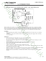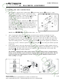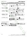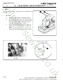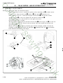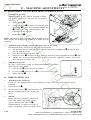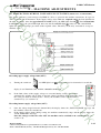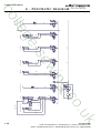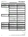
1
MODEL S-4000 CAED Omron CUT AFTER EDGE PARTS AND SERVICE MANUAL MACHINE SERIAL No.: PART NUMBER 97.2430.1.001 T his manual is valid from the machine serial number M241429 AMF is trademark of AMF Group, Inc. 01/2010 MODEL S-4000 CAED Omron CUT AFTER EDGE PARTS AND SERVICE MANUAL MACHINE SERIAL No.: PART NUMBER 97.2430.1.001 T his manual is valid from the machine serial number M241429 AMF is trademark of AMF Group, Inc. 01/2010 97.2430.1.001 CUT AFTER EDGE 97.2430.1.001 CUT AFTER EDGE 97.2430.1.001 CUT AFTER EDGE 97.2430.1.001 CUT AFTER EDGE 97.2430.1.001 CUT AFTER EDGE 97.2430.1.001 CUT AFTER EDGE S-4000 CAED Omron S-4000 CAED Omron S-4000 CAED Omron S-4000 CAED Omron S-4000 CAED Omron S-4000 CAED Omron LIMITED WARRANTY ON NEWAMF REECE EQUIPMENT Warranty provisions: A ninety (90) day limited service labor warranty to correct defects in installation, workmanship, or material without charge for labor. This portion of the warranty applies to machines sold as ”installed” only. A one (1) year limited material warranty on major component parts to replace materials with defects. Any new part believed defective must be returned freight prepaid to AMF Reece, Inc. for inspection. If, upon inspection, the part or material is determined to be defective, AMF Reece, Inc. will replace it without charge to the customer for parts or material. Service labor warranty period shall begin on the completed installation date. Material warranty shall begin on the date the equipment is shipped from AMF Reece, Inc. Exclusions: Excluded from both service labor warranty and material warranty are: (1) Consumable parts which would be normally considered replaceable in day-to-day operations. These include parts such as needles, knives, loopers and spreaders. (2) Normal adjustment and routine maintenance. This is the sole responsibility of the customer. (3) Cleaning and lubrication of equipment. (4) Parts found to be altered, broken or damaged due to neglect or improper installation or application. (5) Damage caused by the use of non-Genuine AMF Reece parts. (6) Shipping or delivery charges. There is no service labor warranty for machines sold as ”uninstalled”. Equipment installed without the assistance of a certified technician (either an AMF Reece Employee, a Certified Contractor, or that of an Authorized Distributor) will have the limited material warranty only. Only the defective material will be covered. Any charges associated with the use of an AMF Reece Technician or that of a Distributor to replace the defective part will be the customer’s responsibility. NO OTHER WARRANTY, EXPRESS OR IMPLIED, AS TO DESCRIPTION, QUALITY, MERCHANTABILITY, and FITNESS FOR A PARTICULAR PURPOSE, ORANY OTHER MATTER IS GIVEN BY SELLER OR SELLER’S AGENT IN CONNECTION HEREWITH. UNDER NO CIRCUMSTANCES SHALL SELLER OR SELLER’S AGENT BE LIABLE FOR LOSS OF PROFITS OR ANY OTHER DIRECT OR INDIRECT COSTS, EXPENSES, LOSSES OR DAMAGES ARISING OUT OF DEFECTS IN OR FAILURE OF THE EQUIPMENT OR ANY PART THEREOF. WHAT TO DO IF THERE ISA QUESTION REGARDING WARRANTY If a machine is purchased through an authorized AMF Reece, Inc. distributor, warranty questions should be first directed to that distributor. However, the satisfaction and goodwill of our customers are of primary concern to AMF Reece, Inc. In the event that a warranty matter is not handled to your satisfaction, please contact the appropriate AMF Reece office: Prostejov, Czech Republic Phone: (+420) 582-309-275 Fax: (+420) 582-360-608 e-mail: [email protected] Warranty Registration Card (Please Fax or Mail immediately after installation) Note: All Warranty Claims Void, unless Registration Card on file at AMF Reece HQ Machine model number: (S101, S100, S104, S311, Decostitch, S4000 BH, etc) Manufacturer‘s serial or production number: Installation Site Information: Customer‘s Name: Customer‘s Mailing Address: Customer‘s Telephone Number: Supervising Mechanic‘s or Technician‘s Name: Signature of Supervising Technician: AMF Reece Technician‘s Name: AMF Reece Technician‘s Signature: Type of garment produced at this location? Average Daily Production Expected from this machine? (number of buttonholes, jackets sewn, pants produced, buttons sewn, etc) Any special requirements required at this location? What other AMF Reece Machines are at this location? How can we serve you better? Tovární 837, 796 25 Prostìjov, Czech Republic Fax: +420 582 360 606, e-mail: [email protected], website: www.amfreece.com S4000 CAED Omron TABLE OF CONTENTS A - INTRODUCTION 1. Basic information ............................................................................................ 1-1 2. Safety device and labels ................................................................................ 1-2 3. General machine parts description ................................................................ 1-3 4. Specifications .................................................................................................. 1-4 5. Instructions for operator safety and maintenance ....................................... 1-5 6. Special accessories .......................................................................................... 1-6 B - MACHINE ASSEMBLY 1. Content of the shipping box .......................................................................... 1-8 2. Accessories ...................................................................................................... 1-8 3. Power and air connection .............................................................................. 1-9 4. Head pmeumatic ............................................................................................. 1-10 5. Installation of thread holder .......................................................................... 1-11 C - PROPER APPLICATION 1. Power Up/ Home position ............................................................................. 1-12 2. Needle installation .......................................................................................... 1-13 3. Threading ......................................................................................................... 1-14 D - MACHINE CONTROLS 1. Progress of sewing .......................................................................................... 1-15 2. Operator control panel push buttons and switches .................................... 1-16 3. Control panel information .............................................................................. 1-17 4. The programming menu ................................................................................. 1-17 5. Tests .................................................................................................................. 1-20 6. Program version .............................................................................................. 1-22 7. Schema of programming ................................................................................ 1-23 8. Parameter checklist ......................................................................................... 1-24 E - MACHINE ADJUSTMENTS 1. Machine home position .................................................................................. 1-25 2. Adjustment of the shifter ............................................................................... 1-25 3. Principles for machine adjustment ................................................................ 1-25 4. Needle bar ....................................................................................................... 1-26 5. Bite ................................................................................................................... 1-27 6. Feeding ............................................................................................................. 1-29 7. Clutch ............................................................................................................... 1-30 8. Stitch Density .................................................................................................. 1-30 Released 10/2009 e-mail: [email protected]; [email protected], website: www.amfreece.com Phones: +420 582 309 146 (Service), +420 582 309 286 (Spare Parts); Fax: +420 582 360 606 S4000 CAED Omron TABLE OF CONTENTS E - MACHINE ADJUSTMENTS 9. Looper adjustments ........................................................................................ 1-31 10. Home position of the clamp plate ............................................................... 1-34 11. Clamp plate adjustment ............................................................................... 1-35 12. Trimming mechanism adjustment ................................................................ 1-35 13. Adjustment of the clamp plate change-over .............................................. 1-36 14. Adjustment of machine head clamping foot .............................................. 1-37 15. Thread draw off ............................................................................................ 1-37 16. Thread tension ............................................................................................... 1-38 17. Thread trimming ............................................................................................ 1-38 18. Cuts-off blow off .......................................................................................... 1-39 19. Thread blow off (special accessory) .......................................................... 1-40 20. Adjustment of stop sensor position ........................................................... 1-40 21. Replacement of the belt ............................................................................... 1-41 22. Protection during voltage fluctuation (special accessory) ....................... 1-42 23. Optical sensor - Adjustment ........................................................................ 1-43 F - MACHINE MAINTENANCE 1. Cleaning and maintenance of the machine .................................................. 1-44 2. List of regular services ................................................................................... 1-46 3. Schema of group lubrication ......................................................................... 1-47 4. Machine lubrication ........................................................................................ 1-48 5. Disposal measures .......................................................................................... 1-50 G - PNEUMATIC DIAGRA Pneumatic diagram .............................................................................................. 1-51 H - ELECTRICAL DIRAGRAM Electrical diagram ................................................................................................ 1-52 Released 10/2009 e-mail: [email protected]; [email protected]; website: www.amfreece.com Phones: +420 582 309 146 (Service), +420 582 309286 (Spare Parts); Fax: +420 582 360 606 S-4000 CAED Omron A - INTRODUCTION 1 . BA S I C I N F O R M AT I O N The sewing machines S-4000 CAED are designed and produced to be very reliable. Important design goals have been achieved to provide a safe machine that is simple and inexpensive to maintain. The patented rotary needle bar shaft drive, a major benefit, delivers longer needle bar life. The added benefits of lower vibration and less noise, translate into less operator fatigue. Simple buttonhole length adjustment located outside the machine, eliminates the need for tilt back, while the quick stop repair function delivers safety and makes repairs easier. A halogen work light is included with the S-4000 CAED and LS, to enhance operator safety and product quality. Special electronic and mechanical safety devices protect the operator and the machine. There is a special power lock out switch that permits the machine to be locked in the off position, so that it cannot be cycled accidentally. There is an emergency off switch. There is a low air pressure detector that will not permit machine operation if air pressure is dangerously low. There are safety-warning labels on the machine in all areas that require special care. These must not be removed. If they are lost replace them immediately. You are the most important safety equipment of all. Be sure you understand the proper operation of the machine. Never remove safety mechanisms or labels. We have made every effort to provide the safest possible machine, but without complete knowledge of how this machine operates, and the use of proper care by the operator, this machine can cause serious injury or death. That is why there are safety warnings throughout these instructions that carry one of these messages. D A N G E R ! Possible loss of life. WA R N I N G ! Possible serious injury or machine damage. N OT I C E ! Possible injury or machine damage. We recommend that service workers from AMF Reece oversee the installation and initial training of your mechanics and operators. The most effective safety precaution is a well-managed safety program. Be sure those who use this machine are properly trained. Never disable safety equipment. Always wear safety goggles when operating or servicing the machine. Revised 10/2009 e-mail: [email protected]; [email protected]; website: www.amfreece.com Phone: +420 582 309 146 (Service), +420 582 309 286 (Spare Parts); Fax: +420 582 360 606 1-1 S-4000 CAED Omron A - INTRODUCTION 2 . S A F E TY D E V I C E A N D L A B E L S ➒ ➋ ➎ ➌ ➍ ➓ Ì ➊ ➋ ➌ ➍ ➎ ➏ 1-2 Warning Covers removed, possible injury Grounding Rotational direction Standard Label Needle bar cover ➐ ➑ ➒ ➓ Eye guard Head cover Fan cover Manometer with pressure sensor Machine head Table Frame Revised 10/2009 e-mail: [email protected]; [email protected]; website: www.amfreece.com Phones: +420 582 309 146 (Service), +420 582 309 286 (Spare Parts); Fax: +420 582 360 606 S-4000 CAED Omron A - INTRODUCTION 3 . G E N E R A L M AC H I N E PA RT S D E S C R I P T I O N ➑ ➏ ➐ ➊ Control box Hand wheel Emergency Stop Button Motor Table Top Thread Stand Control Panel 27 Main switch Foot pedal Clamps Up/Down button Air pressure regulator Air pressure adjustment knob Halogen Lamp Rest Pin Warning: when opening the cover, mind your eyes! Revised 10/2009 e-mail: [email protected]; [email protected]; website: www.amfreece.com Phone: +420 582 309 146 (Service), +420 582 309 286 (Spare Parts); Fax: +420 582 360 606 1-3 S-4000 CAED Omron A - INTRODUCTION 4 . S P E C I F I C AT I O N S Machine type Description S 4000 CAED electronical sewing machine for clothing parts stitching with cutting after Sewing speed 1500-3800 stitches/min Stitch density 3-14 stitches/cm Machine clamp foot height Sewing length Knife length Maximum work thickness Bite size Recommended thread Needle system Lubrication Operating Conditions Air pressure 12.7 mm (1/2") 7-50 mm 55 mm to 4 mm (5/32") 1,7 - 3,0 mm thread size 80, 100, 120 (Tex 40-60) Needle 750 SC 90/14, 70/10 (it is possible to order 80/12) semi-automatic according to IEC 364-3, IEC 364-5-51 temperature from +5°C to 40°C, relative air humidity from 30 to 80 % 0.55 MPa (80 PSI) Machine db level Laeg = 74dB; LWA = 87dB; LpC, peak = 103dB Machine head dimension 340 mm (height) x 470 (width) x 250 mm (length) Machine head length Table dimension Table type 62 kg 700 mm (height) x 600 mm (width) x 1100 mm (length) Angle adjustable 1NPE~60Hz 230V/TN-S (according to EN 60204-1) Electrical Requirements 1NPE~50Hz 230V/TN-S (according to EN 60204-1) 10A charakteristic C (according to EN 60947-2) Line Circuit Breaker 1-4 16A charakteristic B (according to EN 60947-2) Revised 10/2009 e-mail: [email protected]; [email protected]; website: www.amfreece.com Phones: +420 582 309 146 (Service), +420 582 309 286 (Spare Parts); Fax: +420 582 360 606 S-4000 CAED Omron A - INTRODUCTION 5 . I N S T RU C T I O N S F O R O P E R ATO R S A F E TY A N D M A I N T E NA N C E When installing the machine we recommend the minimum clearances noted above around the machine. Read all of the instructions that follow. DO NOT PUT THE MACHINE INTO OPERATION UNTIL YOU ARE COMPLETELY FAMILIAR WITH ALL INSTALLATION AND OPERATING INSTRUCTIONS. DANGER! Before connecting the machine to the power supply, be positive that all safety covers are correctly installed. Always engage the power lockout switch, or disconnect the main power supply, before removing any safety covers. WARNING! Locate the Emergency Stop button. Be sure you know how to use it. Be sure that you have a reliable and uniform power supply. Be sure that all electrical supply lines are in good condition and have no signs of damage to avoid electrical shock. If any covers become damaged, they must be repaired or replaced immediately. Do not touch moving parts of the machine while it is operating. Keep clear of the needle. Always switch off the main power before changing the needle. Before cleaning the machine or performing service to the machine, engage the power lock out switch or disconnect the main power supply. When the machine is not in use engage the power lock out switch or disconnect the main power supply. When this machine is used incorrectly, or is incorrectly maintained, it can be dangerous. Everyone who uses this machine, or maintains this machine, must be completely familiar with this manual. Revised 10/2009 e-mail: [email protected]; [email protected]; website: www.amfreece.com Phone: +420 582 309 146 (Service), +420 582 309 286 (Spare Parts); Fax: +420 582 360 606 1-5 S-4000 CAED Omron A - INTRODUCTION CAUTION! Perform all regular service as described in this manual. If there is any problem with the power supply, turn off the main power switch. Do not remove, paint over, damage or in any way change safety labels. If a safety label cannot be easily read, replace it. Long hair and loose clothing may be dangerous near any machinery. Always contain long hair and avoid loose clothing, so that it cannot be caught by machinery and cause injury. Never use this machine while under the influence of drugs or alcohol. If anything seems to be operating incorrectly in the machine call for maintenance assistance immediately. Be sure that there is adequate light for safe operation. A normal minimum light level is 750 lux. 6 . S P E C IA L AC C E S S O R I E S - machine device, which is not included in the standard equipment of the machine and can be ordered by the customer Vo l t a g e g u a r d - r e l a y H R N 3 5 06.2400.0.004 The machine operation is ensured when the power supply is in range AC 230V ± 10 % (EN 60204-1). It is possible to equip the machine with the relay HRN-35 in case of larger fluctuation of power supply. It prevents the machine from damage and in case of large decrease of power supply, the operator is informed by error message. If the power supply range is exceeded - max 255V and min 185V the voltage guard relay HRN-35 which ensures that machine does not start. After the power supply is in required range, it is possible to start the machine. The manufacturer recommends to use the external stabilizer in case of large fluctuation of power supply. N e e d l e s 7 5 0 S C 8 0 / 1 2 , 90/14 - 1-6 the manufacturer recommends to use these needles when sewing thin material part numbers 02.0750.2.100 (80/12), 02.0750.2.110 (90/14) Revised 10/2009 e-mail: [email protected]; [email protected]; website: www.amfreece.com Phones: +420 582 309 146 (Service), +420 582 309 286 (Spare Parts); Fax: +420 582 360 606 S-4000 CAED Omron A - INTRODUCTION Connector Ø 8 Ê order it if the connecting tube has the inner diameter 8 mm. The connector Ø 10 is supplied with the machine. part number is 12.0008.3.607 Reduction Ë place an order in case you use connections with inch threads (order number 12.0008.3.081) Hand valve Ì to dissipate any air from the machine, order it (air circuit is bled). It is necessary to order the connectors (see below) to the hand valve for connection to the air tubes. part number 12.0008.3.463 Connectors ➍ 12.0008.3.464 ➎ 12.0008.3.466 Ï 12.0008.3.467 Ð 12.0008.3.465 * Ø8 Ø 10 Ø 12 Ø 16 for for for for connection connection connection connection to to to to the the the the tube tube tube tube with with with with inner inner inner inner Ø 8 mm Ø 10 mm Ø 12 mm* Ø 16 mm* To connect the tube with inner Ø 12 and Ø 16, it is also necessary to order Ø 10. Thread Blow - Off Kit Thread Draw - Off Kit - order this device if you would like to use the machine for both, sewing and trimming. without trimming 03.5524.0.023 03.5524.0.004 the device enables thread tail at the needle to be caught above the clamping feet with trimming Revised 10/2009 e-mail: [email protected]; [email protected]; website: www.amfreece.com Phone: +420 582 309 146 (Service), +420 582 309 286 (Spare Parts); Fax: +420 582 360 606 1-7 S-4000 CAED Omron B - MACHINE ASSEMBLY 1 . C O N T E N T O F T H E S H I P P I N G B OX 1. 2. 3. The shipment contains one box. There is a carton with accessories, service manual with parts section and thread stand ➊ in the box. During unpacking the shipment, follow the labels which are on a cover. Ê C AU T I O N : If the machine or crate was damaged in shipment inform the freight company immediately. Check the contents of the crate immediately and report any damage or missing items to the manufacturer immediately, late reports will not be considered! 2 . AC C E S S O R I E S STANDARD ACCESSORIES A package of accessories is supplied with the machine, please refer to page 3-48 for detailed descriptions. The height of the working area is normaly set in range 830 850 mm from the manufacturer. When using this height of the working area, recommended height of the operator seat is in range 430 - 460 mm. The height of the table can be set in range 670 - 880 mm by screws Ì. * It is possible to tilt the operator’s head up to 5°. Remove the shipping strap Ë after unpacking the machine, the use of this strap is recommended anytime the machine is transported (This is valid for all types of tables - parallel, crosswise). ➋ 1-8 Revised 10/2009 e-mail: [email protected]; [email protected]; website: www.amfreece.com Phones: +420 582 309 146 (Service), +420 582 309 286 (Spare Parts); Fax: +420 582 360 606 S-4000 CAED Omron B - MACHINE ASSEMBLY 3 . P OW E R A N D A I R C O N N E C T I O N 1. The machine is equipped with a quick coupler ➍ required with connector tube 10. The connector for inner ∅ of the tube 8 is not supplied with the machine, a customer has to order it. The manufacturer recommends to use connector ➏ for customers who requires to connect the tube with connector NPT. If a customer needs to use a shut off valve ➊ , which allows fast releasing of the air from the circuit, he must order it. A variety of connectors ➋ can be used separately or in combination to adapt to the available input supply hose. It depends on type of the tube which is used by a customer. These connectors are not included in the accessories. A tubing clamp ➌ is provided. N OT E : Parts 2. ➎ for inner ∅ of the ➊, ➋, ➎, ➏ are included in Extra Parts - see 3-48. After air connection check the set air pressure on the dial of the regulator. It should be in range 0.5 - 0.6 MPa. The green pointer ➐ indicates the lowest working air pressure 0.5 MPa, which is set from the manufacturer on the regulator ➑. If the air pressure is lower than 0.5 MPa after connecting the machine to the power supply, „Low Pressure“ message appears on the control panel display. To adjust the working pressure, loosen the regulator cap lock ➓ and turn the regulator cap clockwise to 3. is for setting the minimal operation increase the pressure. Push the regulator cap ➓ down. The LED air pressure. Power supply must be 230 volts. Receptacle plug must meet requirements of IEC standard 364-4-41, its circuit breaker must be minimal 10A with characteristic C according to the EN 60947-2 (or 16A with characteristic B). No other devices must not be connected to the circuit breaker of the socker. The must turn counter clockwise. hand wheel The machine is equipped with a filters which contain capacitors which generate an high frequency leakage current. In order to prevent nuisance tripping, residual current protection device must be protected against these high frequency currents: this is the case for industrial residual current device (example „S“ type). Revised 10/2009 e-mail: [email protected]; [email protected]; website: www.amfreece.com Phone: +420 582 309 146 (Service), +420 582 309 286 (Spare Parts); Fax: +420 582 360 606 1-9 S-4000 CAED Omron B - MACHINE ASSEMBLY 4. H E A D P N E U M AT I C J0I1 BQ2 J0I 2 Ñ* Ê Ë Î J5A Ð Ï Ì J6A J6B Ê — cutting Ë — clamping feet Ì — thread trimming Î — shifting clamping plate MARKING OF HOSES 1-10 J X X X Ï — changing the direction of sewing Ð — blowing off the cut material Ñ — loopers, thread blow off (*Extra parts) J0I1; J0I2 — air supply BQ2 - manometer with pressure sensor air supply 1, 2 — X => marking of pneumatic cylinder 1, 2 — X => auxiliary line A = supply; B = return line; I = valve supply Revised 10/2009 e-mail: [email protected]; [email protected]; website: www.amfreece.com Phones: +420 582 309 146 (Service), +420 582 309 286 (Spare Parts); Fax: +420 582 360 606 S-4000 CAED Omron B - MACHINE ASSEMBLY 5 . I N S TA L L AT I O N O F T H R E A D H O L D E R 1. 2. 3. Put the thread holder together as per the drawing. Position of the ring ➊ enables assembly of the complete holder onto tables with different thickness of the tabletop. The end of the rod with threads ➏ shall not overtop the nut more than 1 mm. Once the ring ➊ is positioned, insert the mat ➋ with the groove towards the ring; place the rod into the opening in the tabletop ➌ (on the right at the back). Tighten the nut ➍ ➎ with the mat underneath. Revised 10/2009 e-mail: [email protected]; [email protected]; website: www.amfreece.com Phone: +420 582 309 146 (Service), +420 582 309 286 (Spare Parts); Fax: +420 582 360 606 1-11 S-4000 CAED Omron C - PROPER APPLICATION 1 . P OW E R U P / H O M E P O S I T I O N ➊ by turning clockwise to the I position. 1. Turn the main power switch on 2. The display is illuminated for a moment and the screen shows the model number. 3. The machine is ready for operation when the Ready message appears on the display and the green LED lights. The machine must be in the home position before starting to sew (to be certain, press the foot treadle and sew one buttonhole). 4. It is possible to install the power voltage control (Voltage monitoring relay HRN 35) into the machine control system. This power voltage control cautions a machine operator if the supply voltage is not in the required range (185V - 255V) and the machine could be damaged - see section E19. N o t e : The power voltage guard is installed in the machine only if a customer has ordered it with the machine. ➊ 1-12 Revised 10/2009 e-mail: [email protected]; [email protected]; website: www.amfreece.com Phones: +420 582 309 146 (Service), +420 582 309 286 (Spare Parts); Fax: +420 582 360 606 S-4000 CAED Omron C - PROPER APPLICATION 2 . N E E D L E I N S TA L L AT I O N WARNING! Before doing this adjustment, switch the machine off and let the remaining compressed air from the machine out. For thin fabrics the machine uses needles order number 02.0750.2.109 (750 SC 70/10— Groz-Beckert) as standard and for thicker fabrice needles order number 02.0750.2.110 (750SC 90/14— Groz-Beckert) – see accessories. I tis possible to use needles order number 02.0750.2.100 (750 SC 80/12 - Groz-Beckert) for thin fabrice – these needles are not in a standard accessory kit. 1. ➊ and open the needle bar cover ➋. Note: The accessories contain the lever ➎ (part number 22.0213.0.000) and screw (part number 08.6000.4.005) with washer (08.6850.4.000) ➏, which is possible to fit to the latch. It allows Using the screwdriver push the latch opening of the cover without using the tool. ➌ and remove the needle. 2. Loosen the screw 3. Insert the new needle so that the long thread groove ➍ is in the rear and the spot for the clamping screw ➌ is in line. Do not install a bent or broken needle. Roll the needle on a flat surface to check for straightness. 4. Tighten the screw Ê Ë ➌ well. Ê ➎ ➏ Revised 10/2009 e-mail: [email protected]; [email protected]; website: www.amfreece.com Phone: +420 582 309 146 (Service), +420 582 309 286 (Spare Parts); Fax: +420 582 360 606 1-13 S-4000 CAED Omron C - PROPER APPLICATION 3. THREADING WARNING! Switch the main machine power off to prevent accidental starting of the machine. Disconnect the air supply and dissipate any stored energy. When threading, see the pictures below. Change the thread tension by nut ➊ according to the sewing conditions. To increase the thread draw off (for example sewing on the thin fabrics) there is an arm installed on the thread draw off lever. ➋ The appearance and quality of the sewing may be affected by one or more of the following: - clamping of the material - thread tension - type of thread (size etc.) - sewn material (thickness, density) 1-14 Revised 10/2009 e-mail: [email protected]; [email protected]; website: www.amfreece.com Phones: +420 582 309 146 (Service), +420 582 309 286 (Spare Parts); Fax: +420 582 360 606 S-4000 CAED Omron D - MACHINE CONTROLS 1 . PROGRESS OF SEWING 1. Bring the machine to the home position according to the section C1. 2. Be certain that the machine is threaded correctly according to the section C3 and insert the work under the clamp feet. 3. When the foot pedal ➌ is pressed to the first position, the work is clamped by the clamp feet. (Releasing the foot pedal will rise the clamp feet). N o t e : It is possible to set in the program the machine start on first pedal position. 4. When the foot pedal is pressed to its second position, the sewing is started. After finishing the sewing and trimming the thread, the machine returns to the home position and the clamp feet rise. 5. When the clamp feet are up, it is possible to move the sewn work for next sewing. 6. Machine can be stopped in any place of the cycle by pressing the Emergency Stop button ➍ which is button placed on the machine head. After releasing the Emergency Stop button, pressing the and pressing the foot pedal, the machine finishes the sewing. 7. If the foot pedal ➌ is pressed before finishing the sewing, the clamp feet will not rise and the machine will sew four cycles instead of two - this is possible to set in program. 8. When the work is done, switch the machine off by the ➎ button. ➍ ➎ ➌ Revised 10/2009 e-mail: [email protected]; [email protected]; website: www.amfreece.com Phone: +420 582 309 146 (Service), +420 582 309 286 (Spare Parts); Fax: +420 582 360 606 1-15 S-4000 CAED Omron D - MACHINE CONTROLS 2 . O P E R ATO R C O N T RO L PA N E L P U S H BU T TO N S A N D S W I T C H E S Indicator signaling that the Emergency stop button is activated. Indicator signaling that the machine is ready to start sewing. “Next” button – move onto the next screen “Previous” button – move back onto the previous screen Button to set up parameter values (in programmable menu) Quick access into parameters used most often Button to set up parameter values (in programmable menu) “Clear” button – return onto the main screen, return onto the screen viewed or changed last “Enter” button (in programmable menu) “Emergency stop” button “Clamp feet” button 1-16 Revised 10/2009 e-mail: [email protected]; [email protected]; website: www.amfreece.com Phones: +420 582 309 146 (Service), +420 582 309 286 (Spare Parts); Fax: +420 582 360 606 S-4000 CAED Omron D - MACHINE CONTROLS 3 . C O N T RO L PA N E L I N F O R M AT I O N Display messages: Standard messages: Error messages: ❍ ❍ ❍ ❍ ❍ Ready index on Emerg. Stop Service mode Wait please Ready F1 Service F6 (MAIN SCREEN) Ready 1239 ❍ Motor not ready ❍ Low voltage ❍ Low air pressure Daily cycle counter ATTENTION! When doing any kind of adjustment, keep your hands off the needle area. The basic machine design is equipped with a pedal control; therefore never place your foot onto the foot pedal. Error messages on the display are mentioned in Tr o u b l e s h o o t in g section. 4. THE PROGRAMMING MENU Main screen Ready á 1239 - press display. To enter the programming menu, press appears on the á appears on the display. The first line of the display indicates the parameter, which is set, and the second line indicates the range of setting. To scroll the lines down press the value of any parameter, press key. Press key, to scroll the lines up, press key to set the first digit. Press second digit starts flashing on the display. To set the value, press key. Press key. To change key. The key. The third digit starts flashing on the display. Repeat this setting until all digits of the parameter are set. To confirm the set value of a parameter, press key. Revised 10/2009 e-mail: [email protected]; [email protected]; website: www.amfreece.com Phone: +420 582 309 146 (Service), +420 582 309 286 (Spare Parts); Fax: +420 582 360 606 1-17 S-4000 CAED Omron D - MACHINE CONTROLS Example: To change the sewing speed from 2000 to 3450 Display Press Display Press á á á (3x) á á á (4x) á á á (5x) á á á Display - maximal speed. Range 1000-3800 spm. 0 - selecting the number of stitches in slow start. Range 0-3. 1000 - setting the slow start speed at the beginning of the sewing cycle. Range 1. 2. S lo w s ti t c h (0-3) 3. Slow speed (500-1000 rpm) 500-1000 rpm. Ndl up pos 320 - correction of the needle bar upper position. Range 0 - 600 imp. Knife delay (60-135 ms) 120 - setting the knife/draw-off delay. It is possible to set it in range 60-135 4. (0-600) 5. ms. 6. K n i f e t im e (30-200 ms) 100 - setting the timing of the knife/draw-off activation. It is possible to set it in range 30-200 ms. 7. Trim delay (145-200 ms) 8. 150 - setting the trim delay. It is possible to set it in range 145 - 200 ms. Tr i m t i me (30-60 ms) 50 - setting the timing of trim activation. It is possible to set in range 30 - 60 Clamp Delay (0-100 ms) 50 - setting the clamp opening delay at the end of cycle. ms. 9. It is possible to set in range 0-100 ms. 1-18 Revised 10/2009 e-mail: [email protected]; [email protected]; website: www.amfreece.com Phones: +420 582 309 146 (Service), +420 582 309 286 (Spare Parts); Fax: +420 582 360 606 S-4000 CAED Omron D - MACHINE CONTROLS Display 10. Cycle delay (500-2500 ms) 500 - setting the delay between the sewing cycles. Cycling parameter must be activated. It is possible to set it in range 500-2500 ms. 11. C y c l in g (yes/no) no - activation of the machine cycling. It is possible to set Yes / No. 12. Pedal 2steps (1step/2steps) - setting the foot pedal position for sewing start. Possible setting 1 step / 2 steps. 13. Double sew 1 (1, 2 = 1 or 2, 3 = 2) - setting the number of cycle repeat. It is possible to set 1, 2 = 1 or 2, 3 = 2 = 1 or 2. When “2” is set, 2 cycle repeat are selected by holding the pedal while sewing. 14. L cou nt Cou nt Rst 1239 No - total cycles counter. 15. Lcount Co un t Rst 1239 Yes - daily counter restart 16. Mat er. b l ow 40 (1-100 x 10ms) - setting the air blow timming of cut-off material. Range 10-1000ms. 17. Direction (0-30 stitches) - Setting of number of stitches sewn over the fabric/garment edge. Range 0 = set “yes” to restart. 0-30 stitches. This range is necessary to adjust according to the mechanically set sewing density and electronically set sewing speed. 18. Optical sens (Yes/No) Yes 19. T hre ad bl o w 30 (1-100 x 10ms) - optical sensor function activation (Yes/No). - setting the thread blow timming. (If this device is installed on the machine.) Range 10-1000ms. 20. Shi f t ti me (3-9 x 100ms) 4 - To return to the main screen, press setting the clamping plate shift time. Range 300-900ms. key Ready 1239 . 4.1. Quick access into parameters used most often - Maximal sewing speed. Can be set up within the range of 1000 –3800 stitches per minute Double sew (1, 2=1 or 2, 3=2) 1 - Number of rows to be sewn. Possible to set 1, 2 = 1 or 2, 3 = 2. Revised 10/2009 e-mail: [email protected]; [email protected]; website: www.amfreece.com Phone: +420 582 309 146 (Service), +420 582 309 286 (Spare Parts); Fax: +420 582 360 606 1-19 S-4000 CAED Omron D - MACHINE CONTROLS Display Press F3 Counter: to Rst 4538 Di re cti o n (0-10 stitches) 0 - Counter of total number of cycles - Setting up number of stitches sewn over the edge of fabric / workpiece. Return onto the main screen 5. TESTS WARNING! TESTS CAN BE CARRIED OUT BY QUALIFIED SERVICE ENGINEERS ONLY! CAUTION! BEFORE STARTING THE TESTS REMOVE CUTTING KNIFE AND NEEDLE. With the main screen on the display, press enter TEST menu, press Display . Intput tests Low air pres . appears on the display. In order to Off appears on the display. You can browse through the F2 menu down by pressing the button or up pressing the button . INPUT (TESTS) Display 1. Intput tests Low air press Off - this appears on the display in case the air pressure is lower than 0,5 MPa. This parameter checks the switch BQ2. Home sensor 2. Voltage Rly Off Off - The end position sensor. Activate the sensor with a metal item. Home sensor Vo l t a g e R l y On O f f appears on the display. This parameter checks the switch BQ1. 3. - This only input signify if the voltage relay is installed on the machine. If Home sensor Off the power voltage drops below 185V, Vo l t a g e R l y O n appears on the display. This parameter checks the relay VC 1 min. 4. - Once the foot pedal is pressed into the first position, Pedal 1 step Pedal 2 step On Off appears on the display. This parameter checks the switch SB4. Pedal 1 step 5. Pedal 2 step Off Off - After pressing the foot pedal into the second position, Pedal 1 step Pedal 2 step Off O n appears on the display. This parameter checks the switch SB5. 1-20 Revised 10/2009 e-mail: [email protected]; [email protected]; website: www.amfreece.com Phones: +420 582 309 146 (Service), +420 582 309 286 (Spare Parts); Fax: +420 582 360 606 S-4000 CAED Omron D - MACHINE CONTROLS Em Stop 6. Clamp Button On Off - Em Stop After pressing button, Clamp Button Off O f f appears on the display. After releasing the button appears on the display. This parameter checks the switch SA1. Em stop 7. Clamp button On Off - Em stop On On button Clamp button By pressing the clamps appears on the display and clamps close. By pressing this button once more, the clamps are lifted. This parameter checks the switch SB3. 8. Motor ready On - If Motor Ready Off appears on the display, go to the section “Troubleshooting”. 9. CAED sensor On - Correction of the sensor position. If the fabric is inserted, CAED sensor Off Output tests key on the last inputs test screen Clamps Off appears on display. By pressing key you to get to the choose the row you need to change. The changed output is signalized by blinking. Press F2 following screen. Press to go back in tests. Press key to get back to the main screen. Display Output tests 10. Clamps Off - Output tests key ➡ Clamps To activate clamps, press Output tests á Clamps On Output tests key á Clamps Output tests Clamps Off On , confirm clamps close. To lift the clamps, press Off , confirm á and clamps are lifted. This parameter tests the YV2 value. Knife 11. Trim Off Off - To activate the cutting lever and draw off, press Knife Trim Off Off , confirm Knife á On ➡ Trim Off . Cutting lever moves down. This parameter tests the YV1 valve. Revised 10/2009 e-mail: [email protected]; [email protected]; website: www.amfreece.com Phone: +420 582 309 146 (Service), +420 582 309 286 (Spare Parts); Fax: +420 582 360 606 1-21 S-4000 CAED Omron D - MACHINE CONTROL Knife 12. Trim Off Off - key á To activate thread trimming, press Knife Off Off , Off On . This parameter tests the YV3 ➡ Trim confirm Knife Trim valve. 13. Shift Off - key á To activate clamping plate shift, press ➡ Shift On , confirm Shift On and the clamp plate is shifted. This parameter tests the valve YV5 valve. Direction 14. Mater. Blow Off Off - ➡ confirm On Off Direction Mater. Blow Direction Mater. Blow á To activate shifter press the key On , Off and the cylinder for shifter is moved. This parameter tests the YV6 valve. Direction 15. Mater. Blow On Off - ➡ To activate this press the key Direction Direction Mater. Blow On On , confirm On ➡ Mater. Blow On . The clamping foot starts blowing air. This parameter tests the YV7. 16. Thread Blow Off - To activate the thread blow off press the key T hre ad Bl ow On ➡ . Confirm ➡ Thread Blow On , the air starts blowing. This parameter tests the YV8 valve (if this valve is assembled). 6 . P RO G R A M V E R S I O N Ready 1239 á Press the key á F2 á 1-22 á á á Ready á PLC: 21.01 á NT2S: 21.01 1239 . Revised 10/2009 e-mail: [email protected]; [email protected]; website: www.amfreece.com Phones: +420 582 309 146 (Service), +420 582 309 286 (Spare Parts); Fax: +420 582 360 606 S-4000 CAED Omron D - MACHINE CONTROL 7 . PA R A M E T E R C H E C K L I S T PARAMETER MAX SPEED SLOW STITCH SLOW SPEED NDL UP POS KNIFE DELAY KNIFE TIME TRIM DELAY TRIM TIME CLAMP DELAY CYCLE DLY CYCLING PEDAL DOUBLE SEW MATER. BLOW DIRECTION OPTICAL SENS THREAD BLOW SHIFT TIME RANGE SETTING 1000-3800 rpm 0-3 500-1000 rpm 0-600 imp 60-150 ms 30-200 ms 0-200 ms 30-60 ms 0-100 ms 500-2500 ms yes/no 1 step / 2 steps 1, 2 =1 or 2, 3 = 2 10-1000 ms 0-10 stitches yes/no 10-1000 ms 300-900 ms 3500 0 1000 320 120 100 150 50 50 500 No 2 steps 1 40 0 yes 30 400 Revised 10/2009 e-mail: [email protected]; [email protected]; website: www.amfreece.com Phone: +420 582 309 146 (Service), +420 582 309 286 (Spare Parts); Fax: +420 582 360 606 1-23 S-4000 CAED Omron E - MACHINE ADJUSTMENTS 1 . M AC H I N E H O M E P O S I T I O N 1. Needle bar is in the upper position. When making the first stitch, the needle Ê must go into the right side throatplate groove Ë. Mark Ñ on the hand wheel must meet mark Ñ on the pulley cover. ➊ ➋ Ñ 2. ADJUSTMENT OF THE SHIFTER 1. Machine must be in the home position. 2. Tilt the machine, lean it onto the support pin and look at the assembly of the main cam. There must be a minimal play x between the main cam shifting mechanism. If you see the mechanisms clash into each other, lose screws Ï and take out the spring Ð. Loose screws Ñ and move arms Ò Ó from the main cam as much as possible. Check the minimal play x after the adjustment. 3 . P R I N C I P L E S F O R M AC H I N E A D J U S T M E N T 1. Before starting doing adjustments switch the machine into the service mode by pressing the emergency stop button on the machine head and releasing it again. Press the button on the control panel afterwards. “Service mode” message appears on the display. WARNING! 2. 1-24 Press THE MACHINE CANNOT START OPERATION BY PRESSING THE FOOT PEDAL IN THE SERVICE MODE! button to go back onto the main screen. Revised 10/2009 e-mail: [email protected]; [email protected]; website: www.amfreece.com Phones: +420 582 309 146 (Service), +420 582 309 286 (Spare Parts); Fax: +420 582 360 606 S-4000 CAED Omron E - MACHINE ADJUSTMENTS 4. NEEDLE BAR 1. Position of the bell-shaped eccentric Turn the hand wheel Î and loose the fastening screw Ê 1 in the bell-shaped eccentric Ë. Keep turning the hand wheel until the needle bar reaches upper position. Pulley screw Ì on the main shaft is on the same level with the bearing cage screws Í Tighten the fasting screw Ê. NOTE: In order to check this device (home position), turn the hand wheel forward and backward. The needle bar must go down, not up. The needle Ó must start sewing in the direction of the arrow – see the picture. After the adjustment of the eccentric, check the position of loopers and main shaft with the upper shaft. (See loopers adjustment). 2. Setting up the height of the needle bar With the machine in home position, set up the needle bar Ò with the gauge Ï to the height of 16 mm (5/8“) from the top of the throatplate Ð to the low edge of the needle eye. Loosen the setscrew Ñ and move the needle bar up or down as necessary. ➋ ➏ ➑ the first stitch direction Revised 10/2009 e-mail: [email protected]; [email protected]; website: www.amfreece.com Phone: +420 582 309 146 (Service), +420 582 309 286 (Spare Parts); Fax: +420 582 360 606 1-25 S-4000 CAED Omron E - MACHINE ADJUSTMENTS 5. BITE Before setting up the bite, dismantle pulley cover Ë and head cover Ê. 1. Ê Ë Bite cam a) b) c) Check that the machine is in home position. Tilt the machine head onto the support pin Ð . If the adjustment is correct, the second setscrew Ñ of the cam Ò (counter-clockwise) must fit vertically onto the bedplate casting. Preparatory adjustment of the bite is done by tightening the setscrew Ñ of the cam Ò on the shaft. The needle Ó must travel even distance when moving up and down from the up dead centre. Needle upper position Needle stroke Ó Bite 1-26 Revised 10/2009 e-mail: [email protected]; [email protected]; website: www.amfreece.com Phones: +420 582 309 146 (Service), +420 582 309 286 (Spare Parts); Fax: +420 582 360 606 S-4000 CAED Omron E - MACHINE ADJUSTMENTS 2. Setting up the width of the bite Tilt the machine head from the support pin back into the sewing position. The width of the bite is set up from the rear side of the machine head from the space below the motor. Hence the head cover needs to be dismantled. The machine S-4000 is assembled with the throatplate , having the bite range from 1.5 mm (1/16“) to 2.3 mm (3/31“). The width of the bite is adjusted as follows: a) loosen the adjusting screw b) lift up the drawbar to get a wider bite c) bring the drawbar to get a narrower bite d) tighten the adjusting screw 3. Setting up the bite in the throatplate a) the machine must be in the home position – loosen the tightening screw on the bite lever b) turn the hand wheel to lower the needle bar into the bottom dead centre and move it towards the right side throatplate groove c) tighten the tightening screw d) turn the hand wheel to check that the needle Ó has same play on both sides of the throatplate groove. NOTE: This is just a reference adjustment. For final adjustment loosen the eccentric screw and turn slowly the eccentric screw Position the needle in such way that the play is same on both sides of the throatpalte groove. Tighten the eccentric screw . correct incorrect Revised 10/2009 e-mail: [email protected]; [email protected]; website: www.amfreece.com Phone: +420 582 309 146 (Service), +420 582 309 286 (Spare Parts); Fax: +420 582 360 606 1-27 S-4000 CAED Omron E - MACHINE ADJUSTMENTS 6. FEEDING 1. 2. Tilt the machine head onto the support pin. Adjustment of feeding wheels Turn the hand wheel counter-clockwise until the guiding spring snaps into the shifter left arm notch. The feeding lever is on the very top point of the feeding cam. Dismantle the gearwheel safety cover and loosen the screws ➊,➋ on the horizontal gearwheels and the crank drive screw 3. 4. 5. Ò ➌. ➍ in the right ring ➎. Pressing the end of the feeding shaft ➏ against the right ring ➎ you adjust the distance between the left ring ➐ and the end of the feeding shaft Ï to 11 mm. Tighten the adjusting screws ➍ on the right ring ➎. This is the right Loosen two adjusting screws tension adjustment of the left ring on the shaft. Place the right gearwheel ➑ into the gearing with the Ì Ë Ê 11 mm vertical wheel ➒ secure its position with setscrews ➊. Turn the hand wheel counter clockwise until the guiding spring snaps into the shifter right arm notch. The feeding lever is on the very bottom point of the feeding cam. Place the left gearwheel ➓ into the gearing with the vertical ➒ secure its position with setscrews ➋. Push the crank drive towards the left gearwheel ➓ and secure it with the screw ➌. Ñ Í Î wheel You have set up the position of the feeding wheels. Turn the hand wheel to finish the sewing cycle and bring the machine into the home position. Mount the wheel safety cover on. 6. 7. 1-28 Ó Ï Ð Ë Ò The feeding always starts, in other words the clamp plate moves, when the needle is out of the fabric, and it is in the position when the needle tip is right above the fabric. Use a sheet of paper to do the adjustment. You will clearly see needle punctures. If the adjustment is incorrect, set the machine into such a sewing position so that the guiding spring snaps into a shifter arm notch. and adjust its Loosen the screws on the feeding cam position so that the clamp plate moves in the moment of the needle being out of the fabric (above the paper).Tighten the setscrews. Revised 10/2009 e-mail: [email protected]; [email protected]; website: www.amfreece.com Phones: +420 582 309 146 (Service), +420 582 309 286 (Spare Parts); Fax: +420 582 360 606 S-4000 CAED Omron E - MACHINE ADJUSTMENTS 7. CLUTCH Clutch pressure is set up by the manufacturer. Under normal circumstances, it is not necessary to adjust it. The correct torque is 0,42 Nm. Hold the nut Ê and tighten the adjusting screw Ë with a torque wrench. Adjust the torque so that is even on both sides of the clutch. NOTE: If you do not have a torque wrench available, set ends of both screws so that screw-threads overlap nuts edges of 1,5 mm. CAUTION: If the torque is too small, fabric will not be fed in correctly. If the torque is too big, it can damage some parts (gearwheels). 1.5 mm Ê Ë 8 . S T I T C H D E N S I TY 2 Adjust position of the feeding rod Ì in the density lever groove Í in order to achieve right stitch density. Increasing stitch density 1: a) Loosen the hexagonal screw Î and move the rod Ì from the bedplate. That will increase the stitch density. b) Tighten the hexagonal screw Î. Maximal stitch density is 14 stitches per 10 mm. Reducing stitch density 2: a) Loosen the hexagonal screw Î and move the rod Ì towards the bedplate. That will reduce the stitch density. b) Tighten the hexagonal screw Î. Minimal stitch density is 3 stitches per 10 mm. 1 Ì Î Í Revised 10/2009 e-mail: [email protected]; [email protected]; website: www.amfreece.com Phone: +420 582 309 146 (Service), +420 582 309 286 (Spare Parts); Fax: +420 582 360 606 1-29 S-4000 CAED Omron E - MACHINE ADJUSTMENTS 9 . L OO P E R S A D J U S T M E N T Before the adjustment, follow the instructions below: · Turn the hand wheel and see carefully the position of the connecting rod ➊ on both extreme ➋. Angle A ➌ and angle B ➍ should be even. If the angles are not even – loosen the hexagonal erection bolt ➎ and turn the eccentric adjusting bolt nut ➏ as necessary. Tighten the hexagonal erection bolt ➎. positions of the looper movable arm · · · · · Turn the hand wheel to set the needle bar to the upper dead centre. Check that the needle is straight. Tilt the head onto the support pin and check that the mark ➐ on the looper cam ➑ is on the left side. If it is on the right side, take the cam out and turn. Place the machine head back to the operation position. Remove the cover ➒, disconnect pneumatic pipes from the clamping cylinder and take the clamping assembly ➓ out. Remove the throatplate hook. Dismantle the holders with loopers. , trimming hook cover and trimming Ì Ê Ë Ê Í Ï Î Ë ➓ ➒ 1-30 Revised 10/2009 e-mail: [email protected]; [email protected]; website: www.amfreece.com Phones: +420 582 309 146 (Service), +420 582 309 286 (Spare Parts); Fax: +420 582 360 606 S-4000 CAED Omron E - MACHINE ADJUSTMENTS Adjustment of the first looper 1. 2. 3. 4. 5. 6. 7. 8. 9. With the machine being in the home position, loosen the looper cam ➑ screws and set it to the lowest position. and turn the Loosen the adjusting screw looper so that it is vertically towards the opening in the holder. Install the holder with the first looper onto the shaft. and move the Loosen the looper holder screw holder so that the needle goes through the centre of looper opening. There must be 0,4 mm play between the needle and the looper opening. Tighten the looper holder screw . Loosen the looper screw and turn the looper towards the needle so that there is 0,1 mm play between the needle and the looper tip. Turn the hand wheel counter clockwise. Once the needle comes back to the home position from the bottom dead centre, insert the gauge market 1 (wider side of the gauge) between the needle bar holder and the needle bar clamp. Check that the looper tip is centered on the needle and that it is 1 mm above the needle eye. If it is not centered – loosen the looper cam screw and hold it Turn the hand wheel slightly counter clockwise if the distance between the looper tip and the needle eye is larger that 1 mm; clockwise if the distance is smaller than 1 mm. Tighten the looper cam screw . If the looper cam has been re-adjusted, it is necessary to check the play 0,4 mm between the needle and the looper opening. 1. 3. 4. 5. 6. 7. Revised 10/2009 e-mail: [email protected]; [email protected]; website: www.amfreece.com Phone: +420 582 309 146 (Service), +420 582 309 286 (Spare Parts); Fax: +420 582 360 606 1-31 S-4000 CAED Omron E - MACHINE ADJUSTMENTS Adjustment of the second looper 10. 11. 12. 13. 14. 15. 1-32 Insert the second looper onto the looper shaft. Loosen the looper holder screw and move the holder so that the needle goes through the centre of looper opening. There must be 0,4 mm play between the needle and the looper opening. Tighten the looper holder screw. and turn the looper Loosen the looper screw towards the needle so that there is 0,1 mm play between the needle and the looper tip. Turn the hand wheel counter clockwise. Once the needle comes back to the home position from the bottom dead centre, insert the gauge market 2 (narrower side of the gauge) between the needle bar holder and the needle bar clamp. Check that the looper tip is centered on the needle and that it is 1 mm above the needle eye. When adjusting the looper cam, it is necessary to check the set up of the first looper again. 10. 11 . 13. Revised 10/2009 e-mail: [email protected]; [email protected]; website: www.amfreece.com Phones: +420 582 309 146 (Service), +420 582 309 286 (Spare Parts); Fax: +420 582 360 606 S-4000 CAED Omron E - MACHINE ADJUSTMENTS 1 0 . H O M E P O S I T I O N O F T H E C L A M P P L AT E 1. Home position of the clamp plate before sewing: a) conical gear wheels ➊ on the feeding shaft are disjointed by the vertical conical gear wheel. b) clamp plate is placed on the right side (to the head casting) 2. If the feeding wheels are not disjointed, proceed as follows: a) loose the worm gear wheel screws ➋ of the main shaft, hold the worm gear and turn the hand wheel counter clockwise or clock wise as necessary. Tighten the screws. Note: If the adjustment is correct, the conical wheels must be disjoined in the home position and the first needle puncture/stitch must go into the right throatplate groove. Ê Ë Revised 10/2009 e-mail: [email protected]; [email protected]; website: www.amfreece.com Phone: +420 582 309 146 (Service), +420 582 309 286 (Spare Parts); Fax: +420 582 360 606 1-33 S-4000 CAED Omron E - MACHINE ADJUSTMENTS 1 1 . C L A M P P L AT E A D J U S T M E N T 1. If the distance between the clamp plate cover ➊ and the throatplate edge instructed in items 2 and 3. Recommended distance – 0,2 mm. 2. Loosen the nut 3. Insert the gap gauge 0,2mm into the gap between the clamp plate cover ➋ is too large, proceed as ➌ in the lever groove ➍. ➊ and the throatplate edge ➋. Move the clamp plate ➎ onto the gauge and secure the position by tightening the nut ➌. ➋ Ì Î ➊ 0,2 mm Í 12. TRIMMING MECHANISM ADJUSTMENT If the mechanism does not trim properly, do the following: * Disconnect the air supply, close the clamp feet and move the clamp plate to the left from the shear edge. 1. Check the shear knife ➊ and throatplate Ì edges ➋. If they are damaged, they can be sharpened or replaced with new parts. 2. 1-34 Puss the trimming mechanism from the top by your hand ➌ and check whether the shears slightly overlap along the shear edge. If they do not overlap, loosen the screw ➍ M4 and turn the studs ➎. Secure the position by tightening the screws M4. Ò ➊ Î Í ➏ ➐ ➑ ➋ Revised 10/2009 e-mail: [email protected]; [email protected]; website: www.amfreece.com Phones: +420 582 309 146 (Service), +420 582 309 286 (Spare Parts); Fax: +420 582 360 606 S-4000 CAED Omron E - MACHINE ADJUSTMENTS 3. Secure the correct position of the mechanism with the stopper stopper 4. ➏ in the upper dead centre and the ➐ in the plate in the bottom dead centre. Correct adjustment of the stop screw - loosen the nut ➏: ➑ ➏ until it touches the cutting lever ➒ - move the mechanism ➌ by your hand to check whether the motion has not been embarrassed - secure the correct position by tightening the nut ➑ ➓ Correct adjustment of the stopper ➐ in the bottom dead centre: - turn the stop screw 5. - tilt the machine head - loosen the screws ➓ - with your hand push the trimming mechanism into the bottom dead centre - push the stopper ➐ onto the knife ➊ and secure its position by tightening the screws ➓. - check again, whether the motion has not been embarrassed 6. Take a blank sheet of paper and insert it into the trimming mechanism. Push the trimming mechanism with your hand. The cut must be neat. If it is not, proceed as per the instructions 1 – 6. 1 3 . A D J U S T M E N T O F T H E C L A M P P L AT E C H A N G E - OV E R Standard set up of the device is 2 mm. It is the minimal value for the knife to go through firmly. With such set up following results can be achieved: 1,7 mm 3 mm If you wish to shorten the distance between stitches and cut fabric, you can adjust the value with the nut ➊ and the screw ➋; to 3 mm at the most. Otherwise the knife may cut stitches. 1,7 mm 1 mm NOTE: The set value must never be smaller than 2 mm, because of the knife, which can get damaged in such case! 2 - 3 mm Adjustment instructions: - tilt the machine head - loosen the nut ➊ ➊ ➋ ➋ and set up the required distance - secure the position with the nut ➊ - turn the screw Revised 10/2009 e-mail: [email protected]; [email protected]; website: www.amfreece.com Phone: +420 582 309 146 (Service), +420 582 309 286 (Spare Parts); Fax: +420 582 360 606 1-35 S-4000 CAED Omron E - MACHINE ADJUSTMENTS 1 4 . A D J U S T M E N T O F M AC H I N E H E A D C L A M P I N G F OOT 1. Adjustment of the uplift Adjustment must be done with air switched on. Make sure the foot is open. If it is not, press the feet button to activate it. a) loosen the nut ➊ b) turning the screw mechanism c) ➍ ➋ ➋ Ê Î clockwise, the clamping foot moves away from the clamping mat ➌. Turning the screw counterclockwise, the mechanism comes forward. tighten the nut ➊ NOTE: once the foot uplift is adjusted and the machine is in its home position, the clamping foot should not be higher than the needle tip. Ì ➍ Í 2. Adjustment of the clamping foot directing at the centre of the needle Check that the foot is closed. If it is not, press the feet button. a) turn the hand wheel to make sure the needle does not hit the clamping feet ➍. If they do, then take the following steps: b) press the feet button to open the foot c) loosen the screw ➎ and move the foot arm away from the needle and tighten the screw ➎ again. d) with the foot closed, turn the hand wheel again to see that the adjustment is correct. In that case the needle must not hit the foot. 3. Adjustment of pressure To ensure a good quality sewing, it is important the clamp feet hold the fabric along its entire length. a) close the feet ➏ by pressing the feet button. b) loosen the nuts ➐ and turn the screw ➑ to set the feet in the right position. c) tighten the nuts ➐. ➑ ➐ ➏ the same pressure 1 5 . T H R E A D D R AW O F F 1. a) Adjustment of the end thread If there are some skipped stitches at the beginning of sewing or the cycle is not finished, do the following: loosen the screw ➊ b) turn the draw off lever ➋ counterclockwise so that the remaining thread in the needle gets longer. 2. Stitching Follow the above-mentioned procedure in cases some stitches skip during sewing process. Turn the draw off lever ➋ counterclockwise. It enlarges the loops at loopers, which then catches the stitches better. 1-36 Ê ➋ Revised 10/2009 e-mail: [email protected]; [email protected]; website: www.amfreece.com Phones: +420 582 309 146 (Service), +420 582 309 286 (Spare Parts); Fax: +420 582 360 606 S-4000 CAED Omron E - MACHINE ADJUSTMENTS 16. THREAD TENSION Correct thread tension affects the final appearance of sewing. The tension changes with the change of material sewn. The thinner and the more elastic material is, the wider the thread tension must be opened. When replacing any part affecting the thread passing, check the smooth finish of surfaces getting in touch with thread. • • Turn the tension knob thread tension. ➊ clockwise to increase the Ê Turn the tension knob ➊ counterclockwise to decrease the thread tension. NOTE: If there is too much thread tension when sewing light and elastic materials, the workpiece can deflect in the sewing area and the final look is not nice. 17. THREAD TRIMMING The trimming mechanism ensures correct trimming of all treads after finishing the last stitch. The trimming hook, which moves in the direction of the arrow, pulls both thread ends A, B. Once the hook is close to the uplift, it guides the left side of the loop A on the knife edge. The thread is trimmed. 1. Adjustment of the trimming cylinder a) tilt the machine head onto the support pin and close the air supply. Push out the piston ➊ of the cylinder ➋ to the possible limit. c) check that the lever ➌ does not overlap the surface of the plate If the lever is above the surface, do the following: loosen the screw ➏. d) loosen the nut e) position. tighten the nut b) ➎ and by using some tools (pliers), turn the piston ➊ of the cylinder ➋ clockwise. It will ensure the lever ➌ is in the right the shaft f) ➍. ➎ and the screw ➏. Check, there is no axial play on ➐ after the adjustment. if there is some play on the shaft, loosen the screw ➏, move the ➐ to the left so that the lock ring 8 touches the cut in the plate ➌. Move the lever to the right until it stops and tighten the screw ➏. shaft Revised 10/2009 e-mail: [email protected]; [email protected]; website: www.amfreece.com Phone: +420 582 309 146 (Service), +420 582 309 286 (Spare Parts); Fax: +420 582 360 606 1-37 S-4000 CAED Omron E - MACHINE ADJUSTMENTS 2. Adjustment of the trimming hook a) press the piston ➊ of the trimming cylinder ➋ down to the maximal limit and loosen the screw b) ➒ of the trimming actuator ➓. turn the trimming actuator ➓ and set the 1.0 mm play between the throatplate and the trimming c) hook tip. tighten the screw d) ➒ of the trimming actuator ➓. open the air supply and by switching the trimming cylinder valve check that the actuator not hit the bedplate casting. ➓ does 1 8 . C U T S - O F F B L OW O F F Cuts-off are blown off through openings in the right arm of the clamping feet by air forced in. 1. Regulation of airflow The airflow can be regulated with a choke placed on YV7 branch. Turn the screw clockwise to reduce the airflow. Turn the screw counterclockwise to increase the airflow. 2. Regulation of air blow period This function is operated directly from the operating panel display. Press F1→ F3 → Mater.blow. The range of air blow is 10-1000 ms. 1-38 Revised 10/2009 e-mail: [email protected]; [email protected]; website: www.amfreece.com Phones: +420 582 309 146 (Service), +420 582 309 286 (Spare Parts); Fax: +420 582 360 606 S-4000 CAED Omron E - MACHINE ADJUSTMENTS 1 9 . T H R E A D B L OW O F F ( S P E C IA L AC C E S S O RY ) Thread blow off is ensured by a pipe placed in the bedplate under the throatplate and air forced into the pipe. 1. Regulation of airflow The airflow can be regulated with a choke placed on YV8 branch. Turn the screw clockwise to reduce the airflow. Turn the screw counterclockwise to increase the airflow. 2. Regulation of air blow period This function is operated directly from the operating panel display. → F3 → Thread blow Off. Press F1→ The range of air blow is 10-1000 ms. 2 0 . A D J U S T M E N T O F S TO P S E N S O R P O S I T I O N Follow the instructions to adjust the position of the sensor: 1. 2. Switch the machine over into the service mode – see section E2. Turn the hand wheel until the stop disc thumb ➊ is placed vertically above the sensor 3. Loosen the sensor screws screws 4. 5. 6. 7. 8. ➋. ➌ and move the holder ➍ to the right to the limit position. Tighten the ➌. Loosen the screw M3 ➎ and adjust the position of the sensor so that the stop disc thumb ➊ is center lined with the sensor marker ➏. The indicator ➐ on the sensor lights up red. Tighten the screw M3 ➎. Tilt the machine head back into operating position. Press F6 on the control panel to bring the machine into the operation mode. Switch the machine on and check the correct setting. The needle bar stops in the home (upper) position. Revised 10/2009 e-mail: [email protected]; [email protected]; website: www.amfreece.com Phone: +420 582 309 146 (Service), +420 582 309 286 (Spare Parts); Fax: +420 582 360 606 1-39 S-4000 CAED Omron E - MACHINE ADJUSTMENTS 2 1 . R E P L AC E M E N T O F T H E B E LT 1. Dismantle the pulley cover 2. Turn the hand wheel screw 3. 4. 5. 6. 7. 8. 9. 10. 11. ➏ ➊ by loosing the screws M4 ➋. ➌ to set the position of the shaft so that the screw ➍ on the pulley ➎ levels the on the bearing housing. Secure the position with the holder 24.0030.0.000 ➐, which is a part of the accessory. With the screw ➏ mount the holder to the bearing housing. Turn the needle bar shaft pulley ➑ until the needle bar comes to the upper position. Secure the position with the holder 24.0024.0.000 ➒, which is a part of the accessory. With the screw ➓ mount the holder to the bearing housing. Turn the motor pulley until the marks on the motor flange and roller level. on the motor flange and the motor with the flange downwards in order to Loosen the screws mount the belt. Fit the belt onto the pulley of the shafts ➎, ➑ and motor pulley . Move the flange together with motor upwards. This is the way to tension the belt . Tighten the screws to secure the are leveled. flange. Make sure the marks Remove the pulley holders ➐,➒. Check the adjustment by pressing the pedal. The needle bar must be in the top dead centre. Small changes in the position of the needle bar can be changed in program parameters: a) needle bar just before top dead centre press => => „Ndl up pos ....imp“ increase the value to reach correct position of the needle bar press , to go back to the operation mode b) needle bar behind top dead centre reduce the value to reach correct position of the needle bar press , to go back to the operation mode 1-40 Revised 10/2009 e-mail: [email protected]; [email protected]; website: www.amfreece.com Phones: +420 582 309 146 (Service), +420 582 309 286 (Spare Parts); Fax: +420 582 360 606 S-4000 CAED Omron E - MACHINE ADJUSTMENTS 2 2 . P ROT E C T I O N D U R I N G VO LTAG E F L U C T UAT I O N ( S P E C IA L AC C E S S O RY ) The special accessory, guard voltage relay HRN-35 (VC1), is placed in the machine control box. It is pre-set and sealed from the manufacturer. If the supply voltage runs within the required range, the Led light Un on the relay lits green. Once the upper limit is exceeded (255V), the LED lights lits red . If the bottom limit is exceeded (185V) the green LED light turns out and the red LED light comes on. The control LED lights turn out if the voltage goes back to the required values. The delay of the relay activation is set up to a minimal value. Exceeding upper supply voltage limit (255V) a) Turning the switch on , red LED light is on . Supply voltage for electronics is cut off, the display is not illuminated, the machine cannot be turned on. b) If the limit values of the supply voltage are exceeded during sewing, the machine automatically switches off in order to prevent control electronics from damaging. Once the value gets back to normal (185V - 255V), the machine can be switched on in a standard way (see section C1). Exceeding bottom supply voltage limit (185V) a) b) Once the voltage drops below the bottom limit, the display shows the „LOW VOLTAGE“ message and the machine cannot be switched on. If the supply voltage drops during sewing, the machine automatically stops and the display shows the „LOW VOLTAGE“.message. Once the voltage reaches the value 185V the machine can be switched on in a standard way (see section C1). Revised 10/2009 e-mail: [email protected]; [email protected]; website: www.amfreece.com Phone: +420 582 309 146 (Service), +420 582 309 286 (Spare Parts); Fax: +420 582 360 606 1-41 S-4000 CAED Omron E - MACHINE ADJUSTMENTS 23. OPTICAL SENSOR - ADJUSTMENT Loosen the holder of the optical sensor by loosing the screew M4 and adjust it in such way so that the ray of the optical sensor projected by the sensor meets the glass eye in throat plate and returns back to sensor. The sensor is switched on. After adjusting the sensor, tighthen the screws on holder. In case the fabric is put in front of the glass eye for example, the control light of sensor is switched off. To adjust the sensitivity of the sensor, use the control element on sensor. To decrease the sensitivity, turn this element into the left until the sensor light starts blinking. Then turn the element back until the light stops blinking. It is also possible to check the signal from sensor in output tests, see section D5. Screw M4 Fiber Sensor optic Fiber optic signal Glass eye Throat plate Caution! In order to ensure correct function of the sensor, keep the sensor eye clean, especially from lubrication. 1-42 Revised 10/2009 e-mail: [email protected]; [email protected]; website: www.amfreece.com Phones: +420 582 309 146 (Service), +420 582 309 286 (Spare Parts); Fax: +420 582 360 606 S-4000 CAED Omron F - MACHINE MAINTENANCE Caution: Check the condition of electric cables; whether they are not damaged. Check that all safety covers are in good condition. Replace any damaged covers! Do not put your fingers in the sewing needle area in any cases! Do not modify the machine in any way, which interfere the safety factors. Do not plug in external lights or other devices into the electrical system of the machine Warning: Do not miss out regular maintenance checks. If the electricity supply breaks down, switch off the main switch. Do not damage, modify or remove the safety labels. Do not operate the machine impaired or intoxicated. Make sure the workplace is illuminated with at least 750 Luxs 1 . C L E A N I N G A N D M A I N T E NA N C E O F T H E M AC H I N E 1. 2. 3. 4. 5. Switch off the power supply and disconnect the air supply. For cleaning and lubrication dismantle the cover ➊ and take out the clamp foot mechanism ➋ . Remove material waste from the clamping area. Open the needle bar cover ➌ and clean the guides ➍ and thread draw off ➎ from thread waste. Clean the sewing mechanism - throatplate and loopers from fabric and thread waste. ➌ ➊ Lubricate the machine as in section F 4. ➋ ➎ ➍ ➍ Revised 10/2009 e-mail: [email protected]; [email protected]; website: www.amfreece.com Phone: +420 582 309 146 (Service), +420 582 309 286 (Spare Parts); Fax: +420 582 360 606 1-43 S-4000 CAED Omron F - MACHINE MAINTENANCE 6. Take out the filter cover ➏ with the cleaning pad ➐. Beat or hoover the pad. In case of severe fouling, wash the pad in washing liquid. Do the same maintenance with the back filter. 7. Maintenance of the filter and regulator Filter jar ➑ – the polycarbonate filter jar must not in any case come into contact with synthetic oil, thinning agent, coal-oil, or other aroma hydrocarbon. For cleaning purposes, use neutral cleaning agents only. Automatic condensate separator – maximal length of the condensate drain can be 5 m. It must be placed in the way so that the condensates can continually drain away. If the device does not work: a) check, if the input pressure is bigger that the output pressure set b) check the cleanness of the valve seating c) check, if the spring or membrane are not damaged d) check out the direction of air flow Exchange of the filter pad ➒ Conditions • decline of flow supply • sudden drop of pressure • if the pressure drops onto 0.7 bars • after a year of operation (in case it has not been changed) ➑ take out the filter pad ➒ with the rectifier disk ➓ a) unscrew the filter jar b) c) d) e) remove the old filter pad and replace it with anew one fit the rectifier disk ➓ into the new filter pad ➒ and put both back in place screw the filter jar back in 8. Check the mechanisms visually, especially the area of the sewing mechanism. 9. Once the maintenance and visual checking is completed, put the clamping foot mechanism back in place. 1-44 Revised 10/2009 e-mail: [email protected]; [email protected]; website: www.amfreece.com Phones: +420 582 309 146 (Service), +420 582 309 286 (Spare Parts); Fax: +420 582 360 606 S-4000 CAED Omron F - MACHINE MAINTENANCE 2 . L I S T O F R E G U L A R S E RV I C E S 1x day (8 hours) cleaning sewing devices and machine frame Lubrication of mechanisms – see section F4. visual checking of internal and external mechanisms Filling the oil tank with oil checking plays in sewing mechanism drive Checking screw joins (keep below mentioned values) Checking condensate in regulator Checking fouling of cleaning pads of the control box. 1x week (40 hours) 1x month (160 hours) Recommended values for srews tihtening ( N m ) : M3 M4 M5 M6 M8 M10 0,5 1,2 2,5 4,0 0,6 1,5 3,0 5,0 8,0 10,0 Revised 10/2009 e-mail: [email protected]; [email protected]; website: www.amfreece.com Phone: +420 582 309 146 (Service), +420 582 309 286 (Spare Parts); Fax: +420 582 360 606 0,8 2,0 4,0 7,0 16,0 30,0 1-45 S-4000 CAED Omron F - MACHINE MAINTENANCE 3 . S C H E M E O F G ROU P L U B R I C AT I O N The machine is mainly equipped with needle bearings and ball bearings, which together with a single-circuit lubrication reduce the maintenance requirements. Circuit I – the supply of lubrication for bite levers, feeding levers and loopers, and worm gear is in the body of the oil gauge. In case of a replacement of some distribution branches, the set of hoses and wicks can be ordered. For mounting, see the picture. Circuit I 1-46 Revised 10/2009 e-mail: [email protected]; [email protected]; website: www.amfreece.com Phones: +420 582 309 146 (Service), +420 582 309 286 (Spare Parts); Fax: +420 582 360 606 S-4000 CAED Omron F - MACHINE MAINTENANCE 4 . M AC H I N E L U B R I C AT I O N 1. Before the machine is switched on for the first time, or after a long time without any operation, it is necessary to lubricate all areas said below. Lubricating oil ESSO TERESSO 32 or oil of similar characteristics can be used. 2. The quantity of oil in the oil tank ➊ with an oil gauge is shown by a red mark. Too much oil can leak into the bedplate! 3. Fill the oil tank with approximately 10 cm3 of oil through the filling hole ➌ ➏ ➎ ➍ ➋. 4. Needle bar mechanism off mechanism ➍ ➌ and draw can be lubricated after opening the needle bar cover ➎. It is also necessary to oil the main cam worm gear through the oiling opening ➏. Areas shown in the picture must be lubricated once (1x) a day (8 hours). ➋ ➊ Revised 10/2009 e-mail: [email protected]; [email protected]; website: www.amfreece.com Phone: +420 582 309 146 (Service), +420 582 309 286 (Spare Parts); Fax: +420 582 360 606 1-47 S-4000 CAED Omron F - MACHINE MAINTENANCE 5. Tilt the machine head onto the support pin and lubricate the areas shown in the picture. ➐ ➑ ➒ ➓ loppers shaft feeding cam feeding shaft bite cam gearwheel trimming shaft looper cam Bring the machine head back into the operation position. 6. Once the machine is well oiled, it is efficient to run the machine at least 10 times with testing material in order to prevent sewn workpieces from possible stains and to wipe out visible oil remains on the machine. ➒ ➐ ➒ ➓ 1-48 Revised 10/2009 e-mail: [email protected]; [email protected]; website: www.amfreece.com Phones: +420 582 309 146 (Service), +420 582 309 286 (Spare Parts); Fax: +420 582 360 606 S-4000 CAED Omron F - MACHINE MAINTENANCE 5. DISPOSAL MEASURES 1. 2. 3. To ensure correct disposal of the machine following environmental measures, it is important to remove non-metal parts from the machine. Once such parts are taken out, it is necessary to partially dismantle the machine; remove covers, disassemble the machine arm and take it out of the frame. Aluminum and hard aluminum parts, non-ferrous metal parts and plastic parts must be disposed separately. Parts described in ad 2 are marked in the spare parts manual as follows: ● aluminum parts ●● non-ferrous metal parts ●●● plastic and non metal alloys Note.: parts assemblies containing aluminum parts, non-ferrous metal parts, steel parts and plastic parts must be dismantled first and then sorted into groups (●, ●●, ●●●). Revised 10/2009 e-mail: [email protected]; [email protected]; website: www.amfreece.com Phone: +420 582 309 146 (Service), +420 582 309 286 (Spare Parts); Fax: +420 582 360 606 1-49 Ř4 Ř4 Ř6 YV1 YV7 A BQ2 Regulator with Air Pressure Switch Ř6 B J1A A J1B Ř6 J7A Ř6 B Ř6 J2A YV2 A Ř4 B J2B J1A1 J1B1 3 Thread Trimm Ř6 YV3 A Ř4 J3B J3A 2 Clamping B 5 JOI1 YV5 A Ř4 Shift Plate J5A 7 Material Blow-off J5B 1 Ř6 J1B Handvalve J1A Knife B 6 Direction J6A Thread Draw-Off KIT YV6 A Ř4 J6B 1-50 B YV8 A Ř4 B Thread Blow-Off KIT 8 Extra parts J8A Extra parts S-4000 CAED Omron G - PNEUMATIC DIAGRAM e-mail: [email protected]; [email protected]; website: www.amfreece.com Phones: +420 582 309 146 (Service), +420 582 309 286 (Spare Parts); Fax: +420 582 360 606 Revised 10/2009 JOI1 S-4000 CAED Omron H - ELECTRICAL DIAGRAM Revised 10/2009 e-mail: [email protected]; [email protected]; website: www.amfreece.com Phone: +420 582 309 146 (Service), +420 582 309 286 (Spare Parts); Fax: +420 582 360 606 1-51 S-4000 CAED Omron H - ELECTRICAL DIAGRAM 1-52 Revised 10/2009 e-mail: [email protected]; [email protected]; website: www.amfreece.com Phones: +420 582 309 146 (Service), +420 582 309 286 (Spare Parts); Fax: +420 582 360 606 S-4000 CAED Omron H - ELECTRICAL DIAGRAM Revised 10/2009 e-mail: [email protected]; [email protected]; website: www.amfreece.com Phone: +420 582 309 146 (Service), +420 582 309 286 (Spare Parts); Fax: +420 582 360 606 1-53 1-54 (see CSN EN60204-1 seg. 5.3.2. - d) MAIN SWITCH FLEXIBLE SUPPLY OUTER WIRING SYSTEM MACHINE WIRING SYSTEM 9 - panel earthing 8 - PLC FX1 earthing 7 - S1 servomotor earthing 6 - Z2 filter earthing 5 - U1 servoamplifier earthing 4 - minus pol secondary earthing 3 - GS1 source earthing 2 - control switchboard doors earthing 1 - control switchboard earthing EARTHING PLACES: OUTER CLAMP FOR BALANCING POTENTIAL DIFFERENCE MACHINE STAND MACHINE BASE MACHINE HEAD COVERS, INSULATION CONTROL SWITCHBOARD FIRST INLET FILTER MACHINE CONNECTING CLAMP CONNECTION TEST ACCORDING CSN EN 60204-1 seg. 19.2 GREEN-YELLOW COLOUR PROTECTION CONNECTION WITH 1,5 mm WIRE PE CLAMP PROTECTION DURING FAILURE: MAIN SUPPLY DISCONNECTION BASIC PROTECTION: ELECTRIC CURRENT SAFETY PROTECTION ACC. CSN EN 61140: PROTECTIVE INTER CONNECTION DIAGRAM OF CONSTRUCTION UNITS FOR s-4000 BUTTENHOLE MACHINE 1N+PE 230V AC 50-60 Hz S-4000 CAED Omron H - ELECTRICAL DIAGRAM e-mail: [email protected]; [email protected]; website: www.amfreece.com Phones: +420 582 309 146 (Service), +420 582 309 286 (Spare Parts); Fax: +420 582 360 606 Revised 10/2009 S-4000 CAED Omron TROUBLESHOOTING TROUBLESHOOTING - TABLE OF CONTENTS 1. MECHANICAL FAULTS ................................................................................................... 2-2 2. CONTROL PANEL DISPLAY ERROR MESSAGES ..................................................... 2-5 3. SERVO ERROR MESSAGES ............................................................................................ 2-6 4. ELECTRICAL FAULTS ..................................................................................................... 2-7 Released 10/2009 e-mail. [email protected]; [email protected]; website: www.amfreece.com Phones: +420 582 309 160 (Service), +420 582 309 286 (Spare Parts); Fax: +420 582 360 606 2-1 S-4000 CAED Omron TROUBLESHOOTING 1 . MECHANICAL FAULTS SYMPTOM Thread breakage Machine fails to sew (Stitch skipping) Machine sews in one spot 2-2 POSSIBLE CAUSE PROBABLE SOLUTION Needle, looper, throat plate damaged Change damaged parts Incorrect needle and sewing mechanism adjustment Check the adjustment of the mechanisms Thread tension is too tight Adjust correct tension Incorrect threading See section C3 for checking. Thread guides polished incorrectly Polish Poor thread quality Replace thread Thread is too heavy for selected needle and throat plate Use recommended thread sizes see section A4 Needle, looper, throat plate damaged Change damaged parts Incorrectly adjusted needle bar height See section E4, point 2 for checking Incorrectly adjusted clearance between needle and throat plate See section E5, point 3 for checking Incorrect loopers timing See section E9 for checking The home position of the clamp plate is adjusted incorrectly. Adjust the stop - see section E11 Released 10/2009 e-mail: [email protected]; [email protected]; website: www.amfreece.com Phones: +420 582 309 146 (Service), +420 582 309 286 (Spare Parts); Fax: +420 582 360 606 S-4000 CAED Omron TROUBLESHOOTING SYMPTOM Stitch skip at the beginning of sewing Stitch skip during sewing POSSIBLE CAUSE PROBABLE SOLUTION Needle, looper, throat plate damaged Change damaged parts Needle thread end is too short See section E15, point 1 Incorrectly adjusted needle bar height See section E4, point 2 Incorrectly adjusted clearance between needle and throat plate See section E5, point 3 Incorrect loopers timing See section E9 Incorrectly adjusted clamp feet pressure See section E 14, point 3 The home position of the clamp plate is adjusted incorrectly. See Section E10 to do the right adjustment Needle, looper, throat plate damaged Change damaged parts Incorrectly adjusted needle bar height See section E4, point 2 Incorrectly adjusted clearance between needle and throat plate See section E5, point 3 Incorrect loopers timing See section E9 Incorrect thread tension adjustment Adjust the tension correctly for section E16 Incorrect threading See section C3 Thread loops are too small See section E15 point 2 Incorrectly adjusted clamp feet pressure See section E14 point 3 The clamp feet are adjusted too far from the sewing See section E14 point 2 Released 10/2009 e-mail. [email protected]; [email protected]; website: www.amfreece.com Phones: +420 582 309 160 (Service), +420 582 309 286 (Spare Parts); Fax: +420 582 360 606 2-3 S-4000 CAED Omron TROUBLESHOOTING SYMPTOM Thread not trimmed at the end of the cycle POSSIBLE CAUSE PROBABLE SOLUTION Trimming knife damaged Replace Low air pressure at trimming cylinder Check supply pressure Incorrect loopers timing See section E9 Incorrect setting of trimming delay Change Trim delay parameter-D4 Trimming length incorrectly set Change Trim time parameter-D4 The trimming knife is damaged Re-sharpen or replace with a new one The edge of the stitching plate is damaged Re-sharpen or replace with a new one Low pressure in the cylinder Check the supply pressure The trimming mechanism to cut fabric adjusted incorrectly Check with the instructions provided in Section E12 Sewing motor turns, machine does not sew Belt broken or loose See section E21 for changing Machine sews continually, does not stop Stopping sensor adjusted incorrectly See section E20 for correct position adjustment Zero pressure on regulator Shut off valve closed Open the shut off valve Low air pressure Filter element dirty Change the filter element Air fitting or tubing obstruction Check supply guides The fabric is not cut at the end of the cycle 2-4 Released 10/2009 e-mail: [email protected]; [email protected]; website: www.amfreece.com Phones: +420 582 309 146 (Service), +420 582 309 286 (Spare Parts); Fax: +420 582 360 606 S-4000 CAED Omron TROUBLESHOOTING 2. E R R O R M E S S A G E S O F T H E C O N T R O L PA N E L D I S P L AY SYMPTOM POSSIBLE CAUSE PROBABLE SOLUTION Hand valve of the regulator switched off (if assembled) Open the hand valve The air pressure in the air supply piping below 0.5 MPa Increase the air pressure Emergency stop, red LED light is ON Emergency Stop button is switched on Release the Emergency Stop button and press F6 key on the control panel Service mode The machine is in the service mode, motor is disconnected Low air pressure Press F6 key on the control panel 3. ERROR MESSAGES OF THE SERVO Power supply indicator PWR - Power supply indication: INDICATOR Alarm indicator (ALM) STATUS Lit green Voltage is good Lit orange - Flashes at a 1 sec. intervals Varning - i.e.: - Exceeded power - Exceeded feed back - Default of inner fan Lit red Alarm - default ALM - Default indication (Alarm indicator): in case default appears, the indicator is switched on. Released 10/2009 e-mail. [email protected]; [email protected]; website: www.amfreece.com Phones: +420 582 309 160 (Service), +420 582 309 286 (Spare Parts); Fax: +420 582 360 606 2-5 S-4000 CAED Omron TROUBLESHOOTING 4. E L E C T R I C A L FA U LT S SYMPTOM When switch in position I, neither the work light, display or the cooling fan operate in position I, When switch display does not operate When sewing operation started, motor does not operate. Contactor KM1 switched on. POSSIBLE CAUSE PROBABLE SOLUTION No power supply Check main power supply or voltage in the socket Fuse F1 failure Replace fuse PN 12.0008.4.665 Power switch QS1 damaged Replace the switch 12.0008.4.835 Power GS1 failure Replace the power 12.0010.4.168 Cable from the display disconnected Check the display connection Display or its control damaged Replace display PN 24.8001.2.002 or control unit PLC 24.8001.0.001, call AMF Reece Service Fuse F2 damaged Replace fuse 12.0008.4.664 Contactor KM1 damaged Replace contactor 12.0008.4.833 Servo U1 error or filter Z2 error Call AMF Reece service or replace servo U1 (page 2-9) or filter Z2 (page 2-9) Error in sewing motor circuit When switching the machine on, the display shows a wrong model of the machine (i.e. S4000 ISBH instead of S4000 BH) 2-6 Incorrect PLC setting Switch the machine off for 1 minute, or restart it, alternatively call AMF Reece service Set the potentiometr on the PLC as in the electric diagram – see Service chapter, Section H) Released 10/2009 e-mail: [email protected]; [email protected]; website: www.amfreece.com Phones: +420 582 309 146 (Service), +420 582 309 286 (Spare Parts); Fax: +420 582 360 606 S-4000 CAED Omron TROUBLESHOOTING SYMPTOM POSSIBLE CAUSE When sewing operation started, Make sure the machine is ready for operation motor fails to operate. Contactor KM1 switched off. Contactor KM1 damaged Press key F6 - see D1, point 6 Replace contactor 12.0008.4.833 Check the Emergency Stop button Replace button 12.0008.4.563 Control unit PLC error Replace the control unit PLC 24.8001.2.001 The needle does not stop in the Position of the sensor BQ1 upper position incorrectly adjusted Adjust according to section E17 Sensor BQ1 failure Replace the sensor 06.2400.0.009 Check the servo amplifier and servomotor To set the servo amplifier - call AMF Reece service, alternatively replace motor (page 2-9) and servo amplifier (page 2-9) Fork is not fitted properly into When sewing operation started, connector X3 air valves do no operate. The air pressure correct. Control unit PLC error The machine does not respond to the signal from the sensor BQ3 PROBABLE SOLUTION Check the connector X3 connection Replace the control unit 24.8001.2.001 The position of the sensor BQ3 adjusted incorrectly Adjust correctly as in Section E23 Faulty sensor BQ3 Replace the sensor 06.2400.0.701 Released 10/2009 e-mail. [email protected]; [email protected]; website: www.amfreece.com Phones: +420 582 309 160 (Service), +420 582 309 286 (Spare Parts); Fax: +420 582 360 606 2-7 S-4000 CAED Omron TROUBLESHOOTING Notes: 2-8 Released 10/2009 e-mail: [email protected]; [email protected]; website: www.amfreece.com Phones: +420 582 309 146 (Service), +420 582 309 286 (Spare Parts); Fax: +420 582 360 606