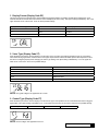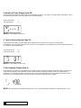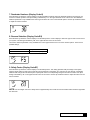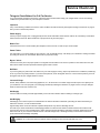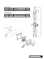
1
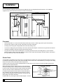
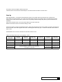
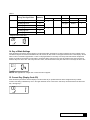
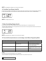
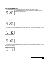
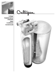
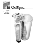
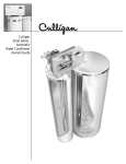
Cat. No. 01021604 Rev. A 02/01/09 DCO # 010884 Owners Guide & Installation Instruction Supplement Soft-Minder® Twin Water Softener Models from 2009 © 2009 Culligan International Company Thank You And welcome to your new world of better living with Culligan water. The Culligan Soft-Minder® Twin Water Softeners are tested and certified by WQA according to WQA S-100 for calcium and magnesium reduction (hardness). For installations in Massachusetts, the Commonwealth of Massachusetts Plumbing Code 248 CMR shall be adhered to. Consult your licensed plumber for installation of the system. This system and its installation must comply with state and local regulations. The use of saddle valves is not permitted. If this is your first experience having soft, conditioned water in your home, you’ll be amazed at the marvelous difference it makes. We promise that you’ll never want to be without it again. With Culligan’s many years of knowledge and experience in water treatment, you can be confident that the model you selected has been designed and engineered to provide years of service with a minimum of care and attention. Some localities have corrosive water. A water softener cannot correct this problem and so its printed warranty disclaims liability for corrosion of plumbing lines, fixtures or appliances. If you suspect corrosion, your Culligan Dealer has equipment to control the problem. Sodium Information: Water softeners using sodium chloride for regeneration add sodium to the water. Persons who are on sodium restricted diets should consider the added sodium as part of their overall sodium intake. This supplement contains important information about the Soft-Minder Twin automatic water conditioner, including instructions covering installation of the control valve, tank adapter, interconnection piping between the two mineral tanks, and timer adjustments. For additional information, please refer to the Model 9100 Service manual packed with the control. Before starting the installation, make certain the water meets the required limitations as shown in the specifications. Review the specifications for the unit to be certain all applications requirements have been met. Also, carefully review the Model 9100 Service Manual, paying particular attention to the regeneration cycle program setting procedure and start-up procedure. Performance Data Sheets are included in this manual for various Culligan Soft-Minder Twin Softener models. Refer to the Performance Data Sheet for your specific softener, as there are slight differences between the models. The softener warranty is located on page 18 of this Owner’s Guide. Attention Culligan Customer: Your local independently operated Culligan dealer employs trained service and maintenance personnel who are experienced in the installation, function and repair of Culligan equipment. This publication is written specifically for these individuals and is intended for their use. We encourage Culligan users to learn about Culligan products, but we believe that product knowledge is best obtained by consulting with your Culligan dealer. Untrained individuals who use this manual assume the risk of any resulting property damage or personal injury. Warning! Prior to servicing equipment, disconnect power supply to prevent electrical shock. Owners Guide & Installation Instruction Supplement Soft-Minder® Twin Water Softener Models from 2009 Table of Contents Page Specifications . . . . . . . . . . . . . . . . . . . . . . . . . . . . . . . . . . . . . . . 4 Introduction. . . . . . . . . . . . . . . . . . . . . . . . . . . . . . . . . . . . . . . . . 5 Preparation . . . . . . . . . . . . . . . . . . . . . . . . . . . . . . . . . . . . . . . . . 8 Installation. . . . . . . . . . . . . . . . . . . . . . . . . . . . . . . . . . . . . . . . . 10 Control Start-up Procedures. . . . . . . . . . . . . . . . . . . . . . . . . . . 12 Diagnostics . . . . . . . . . . . . . . . . . . . . . . . . . . . . . . . . . . . . . . . . 22 Salt Supply, Usage & Service. . . . . . . . . . . . . . . . . . . . . . . . . . 26 Care & Cleaning . . . . . . . . . . . . . . . . . . . . . . . . . . . . . . . . . . . . 27 Service Check List. . . . . . . . . . . . . . . . . . . . . . . . . . . . . . . . . . . 29 Error Codes. . . . . . . . . . . . . . . . . . . . . . . . . . . . . . . . . . . . . . . . 30 Culligan 61 Soft-Minder Twin Performance Data Sheet. . . . . . 31 Culligan 91 Soft-Minder Twin Performance Data Sheet. . . . . . 32 Parts List. . . . . . . . . . . . . . . . . . . . . . . . . . . . . . . . . . . . . . . . . . 33 Records and Data. . . . . . . . . . . . . . . . . . . . . . . . . . . . . . . . . . . 41 Wiring Diagram. . . . . . . . . . . . . . . . . . . . . . . . . . . . . . . . . . . . . 42 Warranty . . . . . . . . . . . . . . . . . . . . . . . . . . . . . . . . . . . . . . . . . . 43 Promise. . . . . . . . . . . . . . . . . . . . . . . . . . . . . . . . . . . . . . . . . . . 44 Table of Contents Specifications Twin Specifications Control Valve SM-61 Model SM-91 Model Reinforced Thermoplastic Reinforced Thermoplastic Overall Conditioner Height Media Tank Design Quadra-Hull Quadra-Hull Media Tank Dimensions (Dia x Ht) 9 x 48 in 10 x 54 in Salt Storage Tank Dimensions (Dia x Ht) 16 x 43 in 18 x 43 in 18 x 43 in Exchange Media, Type and Quantity Underbedding, Type and Quantity Cullex® Media, 1.0 ft3 Cullex® Media, 1.5 ft3 Cullsan® Cullsan® Underbedding, 12 lb Underbedding, 15 lb Exchange Capacity 13,760 gr @ 3.3 lb 21,193 gr @ 5 lb @ Salt Dosage Per Recharge 27,848 gr @ 9.3 lb 42,890 gr @ 14 lb 32,939 gr @ 15 lb 50,732 gr @ 22.5 lb 4130 gr/lb @ 3.3 lb salt dosage 4,240 gr/lb @ 5 lb salt dosage 14.5 in 14.5 in 44.5 in 47.5 in 250 lb or 375 lb 375 lb 10.4 gpm @ 15 psi 10.2 gpm @ 15 psi Total Hardness, Maximum 75 gpg 99 gpg Total Iron, Maximum 5 ppm 5 ppm 8 gpg to 1 ppm 8 gpg to 1 ppm Operating Pressure 20-125 psi 20-125 psi Operating Temperature 33-120°F 33-120°F Electrical Requirements 24V/60 Hz 24V/60 Hz 5 Watts/ 6 Watts 5 Watts/ 6 Watts 2 gpm 2 gpm 67 min 67 min 57 gal 57 gal Efficiency rated dosage1 Freeboard to Media 2 Freeboard to Underbedding 3 Salt Storage Capacity Rated Service Flow @ Pressure Drop Hardness to Iron Ratio, Minimum Electrical Power Consumption, Min/Max Drain Flow, Maximum 4 Recharge Time, Average 5 Recharge Water Consumption, Average 5 1 The efficiency rated dosage is only valid at the stated salt dosage and is efficiency rated according to NSF/ANSI 44. 2 Measured from top of media to top surface of tank threads. (backwashed and drained). 3 Measured from top of underbedding to top surface of tank threads. 4 Backwash at 120 psi (830 kPa). 5 10 minute backwash, 3.3 lb 9” model, 5 lb (2.7kg) 10” model. Culligan Platinum Plus® Series Introduction It’s All So Easy, So Economical, So Efficient, So Enjoyable! Kind To Skin And Complexion Soft water will help prevent red, itchy or dry skin because there are no hardness impurities to cause soreness, no soap curd to coat the skin. Shaving is easier, smoother - either with blade or electric shaver. Bathing And Showering You’ll use far less soap with conditioned water. Use your soap very sparingly - not as you did before soft water. Just a quick rinse removes all lather, leaving your skin pleasantly smooth and silky - because now it’s free of sticky soap curd and film. Saves Washing Costs. Helps Control Environmental Pollution Soft water washes whiter and cleaner with less soap or detergent. Because the hardness impurities are removed, your soap can concentrate solely on washing. People usually find that they can reduce the amount of soap they use substantially. If you normally used a cup per wash load with hard water, try using only 1/3 cup depending on the size of your wash load and the degree of soil. Different amounts are required, but you can use less with softened water. An added bonus is the fact that your washable fabrics will last longer. Super Hair Conditioning Soft water is great for scalp and hair care. No insoluble deposits are formed. Hair is shinier, softer, more manageable. Reduce the amount of shampoo you have normally used. Dishes Are A Delight Washed by hand or in a dishwasher, glassware, dishes and silver wash cleaner, easier. Follow your dishwasher manufacturer’s instructions. Soft water promotes sanitation because no greasy hard water film can form to collect or harbor bacteria. Easier Housekeeping, Gleaming Fixtures You’ll be amazed at the marvelous difference. Just a swish of the cloth, and the bathtub or shower and fixtures are clean and sparkling. Imagine, no scouring! No hard water scum to cause rings, streaks, spots and stains. To keep their gleaming luster, simply wipe fixtures with a towel after use. Formica, tile, walls, floors, woodwork surfaces clean easier, stay clean longer. You’ll save on cleaning aids and save on time. Saves Water-heating Energy, Helps Water-using Appliances Soft water reduces the formation of rock-like hard water scale which encrusts water heaters, hot water pipes, shower heads, and water-using appliances. This scale can cause premature maintenance and failure. Elimination of hard water also provides substantial energy savings because scale acts as an insulator, wasting electricity or gas used to heat water. Savings Galore A water conditioner is frequently referred to as “the appliance that pays for itself”. You’ll find that your savings on soaps, detergents, cleaning aids, and personal care products will help your family’s household budget. And if you place a price on your time, you’ll be most happy with the time saved by your new family servant. Water For Lawns And Household Plants If possible, lawn sprinkling faucets should be supplied with hard water primarily because it is uneconomical to soften so much water. Household plants are much more sensitive than lawns with respect to the kind of water which is best. First, because they receive no rainfall and, second, there is little or no drainage of the soil. Preferably they should be watered with rain water or water which is low in mineral content such as distilled or demineralized water. Softened water is not recommended for house plants because a build-up of sodium in the soil may interfere with efficient absorption of water by the plant root system. Additional information may be obtained from your independently operated Culligan dealer. Introduction How Your Water Conditioner Works Why Water Gets Hard And How It’s Softened All of the fresh water in the world originally falls as rain, snow, or sleet. Surface water is drawn upward by the sun, forming clouds. Then, nearly pure and soft as it starts to fall, it begins to collect impurities as it passes through smog and dust-laden atmosphere. And as it seeps through soil and rocks it gathers hardness, rust, acid, unpleasant tastes and odors. Water hardness is caused primarily by limestone dissolved from the earth by rainwater. Because of this, in earlier times people who wanted soft water collected rainwater from roofs in rain barrels and cisterns before it picked up hardness from the earth. Some localities have corrosive water. A softener cannot correct this problem and so its printed warranty disclaims liability for corrosion of plumbing lines, fixtures or appliances. If you suspect corrosion, your Culligan Man has equipment to control the problem. Iron is a common water problem. The chemical/physical nature of iron found in natural water supplies is exhibited in four general types. 1. Dissolved Iron - Also called ferrous or “clear water” iron. This type of iron can be removed from the water by the same ion exchange principle that removes the hardness elements, calcium and magnesium. Dissolved iron is soluble in water and is detected by taking a sample of the water to be treated in a clear glass. The water in the glass is initially clear, but on standing exposed to the air, it may gradually turn cloudy or colored as it oxidizes. 2. Particulate Iron - Also called ferric or colloidal iron. This type of iron is an undissolved particle of iron. A softener will remove larger particles, but they may not be washed out in regeneration effectively and will eventually foul the ion exchange resin. A filtering treatment will be required to remove this type of iron. 3. Organic Bound Iron - This type of iron is strongly attached to an organic compound in the water. The ion exchange process alone cannot break this attachment and the softener will not remove this type of iron. 4. Bacterial Iron - This type of iron is protected inside a bacteria cell. Like the organic bound iron, it is not removed by a water softener. When using a softener to remove both hardness and dissolved iron it is important that it regenerates more frequently than ordinarily would be calculated for hardness removal alone. Although many factors and formulas have been used to determine this frequency, it is recommended that the softener be regenerated when it has reached 50 - 75% of the calculated hardness alone capacity. This will minimize the potential for bed fouling (Iron removal claims have not been verified by the Water Quality Association). If you are operating a water softener on clear water iron, regular resin bed cleaning is needed to keep the be from coating with iron. Even when operating a softener on water with less than the maximum of dissolved iron, regular cleanings should be performed. Clean every six months or more often if iron appears in your conditioned water supply. Use resin bed cleaning compounds carefully following the directions on the container. Caution! Do not use where the water is microbiologically unsafe or with water of unknown quality without adequate disinfection before or after the unit. Hardness sample kits are available through your local Culligan dealer. Culligan Soft-Minder Twin® Softeners The Culligan Process Your Culligan water conditioner consists of three basic components, (A) the Control Valve, (B) the Mineral Tank, and (C) the Brine System. A. The exclusive Culligan control valve automatically performs a variety of tasks that are necessary for the proper operation of your water conditioner. These tasks, commonly referred to as cycles or operating positions, are: Service, Regeneration, and Brine Refill. 1. Service: While the control valve is in the “Service cycle”, hard water is directed down through the column of Cullex® resin where hardness minerals are removed from the water. The softened water is then directed into your household plumbing lines. The ability of the Cullex resin to remove hardness minerals needs to be periodically replenished; this is referred to as . . . 2. Regeneration: While the control valve is in the “Regeneration cycle”, water is first directed up through the column of Cullex resin to flush accumulated sediment out of the resin and down the drain. Then, the regenerant brine solution is slowly drawn from the bottom of the salt storage tank of the Brine System and is directed down through the column of Cullex resin, restoring the ability of the resin to remove hardness minerals from your water supply. Once completed, the regeneration cycle is followed by . . . 3. Brine Refill: While the control valve is in the “Brine Refill cycle”, a predetermined amount of water is directed to the salt storage tank of the Brine System so that additional salt can be dissolved to provide the brine solution that will be needed for the next regeneration cycle. B. The exclusive Quadra-Hull® Mineral Tank contains the Cullex resin column, Cullsan® underbedding, and an outlet manifold. The number of gallons of hard water that can be softened by the Cullex resin column before it needs regeneration is called the “capacity” of the resin column, and depends upon the amount of hardness minerals in each gallon of water (expressed as grains per gallon) and upon the amount of regenerant brine solution (expressed as pounds of salt) passed through the resin column during regeneration. Your Culligan service person, taking into account the hardness of your water and the amount of softened water your household may reasonably expect to use each day, has carefully established how often the softener will regenerate and how much salt will be used for each regeneration. This will ensure that all of your soft water needs will be fulfilled without using an excessive amount of salt. C. The Brine System consists of a salt storage container and hydraulic Dubl-Safe valve. The salt storage container holds the salt that is used to make the regenerant brine solution. The hydraulic Dubl-Safe valve limits the amount of water that is returned to the salt storage tank during the brine refill cycle. Since a predetermined amount of salt is dissolved with each brine refill cycle, the salt must be periodically replenished in order to maintain efficient operation. Your Culligan service person will be able to tell you about how often salt must be added to the salt storage container. Introduction Preparation Component Description The water conditioner is shipped from the factory in a minimum of four cartons. Remove all components from their cartons and inspect them before starting installation. Control Valve Assembly - Includes the Soft-Minder Twin Control. Small parts packages will contain additional installation hardware, and the conditioner Owner’s Guide. Media Tank - Includes Quadra-Hull® media tank complete with Cullex® ion exchange resin, underbedding and outlet manifold. Salt Storage Tank Assembly - Includes salt storage container with support plate and Dubl-Safe™ brine refill valve and chamber. Bypass Valve - Includes the stainless steel bypass valve and pins. Tools and Materials The following tools and supplies will be needed, depending on installation method. Observe all applicable codes. Note: Check and comply with your state and local codes. You must follow these guidelines. For installations in Massachusetts, the Commonwealth of Massachusetts Plumbing Code 248 CMR shall be adhered to. Consult your licensed plumber for installation of the system. This system and its installation must comply with state and local regulations. The use of saddle valves is not permitted. All Installations • Safety glasses • Phillips screwdrivers, small and medium tip. • Gauge assembly (PN 00-3044-50 or equivalent) • Silicone lubricant (PN 00-4715-07 or equivalent) - DO NOT USE PETROLEUM-BASED LUBRICANTS • A bucket, preferably light-colored • Towels Special Tools • Torch, solder and flux for sweat copper connections • Use only lead-free solder and flux for all sweat-solder connections, as required by state and local codes. • Threading tools, pipe wrenches and thread sealer for threaded connections. • Saw, solvent and cement for plastic pipe connections. Materials • Brine line, 5/16” (PN 00-3031-28 or equivalent) • Drain line, 1/2” (PN 00-3030-82, gray, semi-flexible; or PN 00-3319-46, black, semi-rigid; or equivalent) • Thread sealing tape • Pressure reducing valve (if pressure exceeds 125 psi [860 kPa], PN 00-4909-00 or equivalent) • Pipe and fittings suited to the type of installation • Water softener salt (rock, solar or pellet salt formulated specifically for water softeners) Culligan Soft-Minder Twin® Softeners Application Water quality - Verify that raw water hardness and iron are within limits. Note the hardness for setting the salt dosage and recharge frequency. Pressure - If pressure exceeds 125 psi (860 kPa), install a pressure reducing valve (see materials checklist). On private water systems, make sure the minimum pressure (the pressure at which the pump starts) is greater than 20 psi (140 kPa). Adjust the pressure switch if necessary. Caution! The use of a pressure reducing valve may limit the flow of water in the household. Temperature - Do not install the unit where it might freeze, or next to a water heater or furnace or in direct sunlight. Outdoor installation is not recommended and voids the warranty. If installing in an outside location, you must take the steps necessary to assure the softener, installation plumbing, wiring, etc. are as well protected from the elements (sunlight, rain, wind, heat, cold), contamination, vandalism, etc. as when installed indoors. Location Space requirements - Allow 6-12 inches (15-30 cm) behind the unit for plumbing and drain lines and 4 feet (1.3 meters) above for service access and filling the salt container (See figure 1). Floor surface - Choose an area with solid, level floor free of bumps or irregularities. Bumps, cracks, stones and other irregularities can cause the salt storage tank bottom to crack when filled with salt and water. Drain facilities - Choose a nearby drain that can handle the rated drain flow (floor drain, sink or stand pipe). Refer to the Drain Line Chart, Table 1 (page 11), for maximum drain line length. Note: Most codes require an anti-siphon device or air gap. Observe all local plumbing codes and drain restrictions. The system and installation must comply with all state and local laws and regulations. Waste connections or drain outlets shall be designed and constructed to provide for connection to the sanitary waste system through an air gap of 2 pipe diameters or 25 mm (1 in.), whichever is larger. Electrical facilities - A 10-foot cord and wall mount plug-in transformer are provided. The customer should provide a receptacle, preferably one not controlled by a switch that can be turned off accidentally. Observe local electrical codes. Note: The softener works on 24 volt - 60 Hz power only. Be sure to use the included transformer. Be sure the electrical outlet and transformer are in an inside location to protect from moisture. Properly ground to conform with all governing codes and ordinances. Preparation Installation Use this installation supplement with the Fleck Service Manual and Timer Supplemental Service Manual. This addendum supplements the Fleck 9100 Service Manual and Timer Service Manual. TO HOSE BIBS TREATED WATER OUT DRAIN LINE HARD WATER IN AIR GAP HEATER BRINE TANK WATER METER OR PUMP Figure 1 SOFT-MINDER TWIN Placement • Set the media tanks on a solid, level surface that provides easy access to a water supply, drain system and electricity. • Place the brine system on a flat, smooth, solid surface close to the media tank. • Plumbing should comply with the applicable state and local plumbing codes. • Connect the couplings and yoke assembly to the control valve and tank adapter. Lubricate the O-ring with silicone lubricant. • Lubricate the distributor and tank O-ring seal with silicone lubricant. • The joints near the drain must be soldered prior to connecting the drain line flow control fitting (DLFC). Leave at least 6” between the DLFC and the joints when soldering. Failure to do this could cause damage to the drain module. Teflon tape is the only sealant to be used on the drain fittings. Control Valve A 0.5 gpm BLFC is installed in the control valve. A 0.25 gpm BLFC is included in the control parts pack that needs to be used on 9” tank when salt dosage is less than 5 lbs. Remove the BLFC from the brine valve. Install the BLFC by removing the brine fitting, remove the retainer, remove and replace with the proper size. A white #1 eductor throat and nozzle is packaged with the control valve for use on the 9-inch tanks. See table 2 (page 19) for eductor throat and nozzle selections. When changing the eductor nozzle and throat, remove the eductor assembly mounting screws. Carefully remove the eductor assembly from the control. Unscrew the eductor nozzle and throat and replace with the correct size eductor. Reassemble onto the control valve. Included in the parts pack are drain line flow controls with different gpm capacities. Tank size will determine which size flow control to install. Use the 2.00 gpm for the 9-inch tank and 10-inch tank. See table 2 (page 19) for DLFC selections Install the DLFC by removing the drain line elbow adapter. Unscrew 10 Culligan Soft-Minder Twin® Softeners Figure 2 the retainer, remove and replace with the proper size. Install the retainer and the drain line elbow adapter. The numbered side of the DLFC must face down. Start-Up Place approximately 1” of water above the grid plate (if used) in your salt tank. Salt may be placed in the unit at this time. Place softener in a bypass position. Turn on the main water supply and check for any leaks. Open a cold water faucet near the softener and run a few minutes until the system is free of any foreign material (usually solder) that may have resulted from the installation. Plug unit into electrical outlet. Do not insert meter cable into the meter at this time. Electrical connections must be connected according to codes. Advance the softener control to the backwash position. Slowly shift the bypass into the service position so that the water flows into the mineral tanks. When water appears at the drain, shift the bypass valve to fully open. Continue to backwash until the water at drain is clear. Start REGEN to fill second tank. Backwash until the water at drain is clear. Height of Discharge Above Floor Level Operating - Table 1 Operating Pressure 0 ft (0 m) 2ft (0.6 m) 4 ft (1.2 m) 6 ft (1.8 m) 8 ft (2.4 m) 10 ft (3 m) 30 psi (210 kPa) 60 ft (18 m) 50 ft (15 m) 30 ft (9 m) 15 ft (5 m) Not Allowable Not Allowable 40 psi (279 kPa) 100 ft (30 m) 90 ft (27 m) 70 ft (21 m) 50 ft (15 m) 30 ft (9 m) 12 ft (4 m) 50 psi (349 kPa) 145 ft (41 m) 115 ft (35 m) 80 ft (24 m) 80 ft (24 m) 60 ft (18 m) 40 ft (12 m) 100 ft (30 m) 100 ft (30 m) 85 ft (26 m) 60 ft (18 m) 140 ft (43 m) 120 ft (37 m) 60 psi (419 kPa) 80 psi (559 kPa) 100 psi (699 kPa) Normal Installation should not require more than 100 ft (30 m) of drain line 150 ft (46 m) Installation 11 Control Start-up Procedures Parameter Data PM Display Display Indicator Error/ Information Icon Service Flow Indicator Icon x1000 Indicator Programming Icon Extra Cycle Button Up Button Down Button Features of the Timer: • Power backup that continues to keep time and the passage of days for a minimum of 48 hours in the event of power failure. During a power outage, the control goes into a power-saving mode. It does not monitor water usage during a power failure, but it does store the volume remaining at the time of power failure. • Day-of-the-Week controls. • While in service, the display alternates between time of day, volume remaining or days to regeneration, and tank in service (twin tank systems only). • The Flow Indicator flashes when outlet flow is detected. • The Service Icon flashes if a regeneration cycle has been queued. • A Regeneration can be triggered immediately by pressing the Extra Cycle button for five seconds. • The Parameter Display displays the current Cycle Step (BW, BF, RR, etc) during regeneration, and the data display counts down the time remaining for that cycle step. While the valve is transferring to a new cycle step, the display will flash. The parameter display will identify the destination cycle step (BW, BF, RR, etc) and the data display will read “----”. Once the valve reaches the cycle step, the display will stop flashing and the data display will change to the time remaining. During regeneration, the user can force the control to advance to the next cycle step immediately by pressing the extra cycle button. Setting the Time of Day 1. Press and hold either the Up or Down buttons until the programming icon replaces the service icon and the parameter display reads TD. 2. Adjust the displayed time with the Up and Down buttons. 3. When the desired time is set, press the Extra Cycle button to resume normal operation. The unit will also return to normal operation after 5 seconds if no buttons are pressed. 12 Culligan Soft-Minder Twin® Softeners Queueing a Regeneration 1. Press the Extra Cycle button. The service icon will flash to indicate that a regeneration is queued. 2. To cancel a queued regeneration, press the Extra Cycle button. Regenerating Immediately Press and hold the Extra Cycle button for five seconds. Meter Immediate Control A meter immediate control measures water usage and regenerates the system as soon as the calculated system capacity is depleted. The control calculates the system capacity by dividing the unit capacity (typically expressed in grains/unit volume) by the feedwater hardness and subtracting the reserve. Meter Immediate systems generally do not use a reserve volume. However, in twin tank systems with soft-water regeneration, the reserve capacity should be set to the volume of water used during regeneration to prevent hard water break-through. A Meter Immediate control will also start a regeneration cycle at the programmed regeneration time if a number of days equal to the regeneration day override pass before water usage depletes the calculated system capacity. Time Clock Delayed Control A Time Clock Delayed Control regenerates the system on a timed interval. The control will initiate a regeneration cycle at the programmed regeneration time when the number of days since the last regeneration equals the regeneration day override value. Day of the Week Control This control regenerates the system on a weekly schedule. The schedule is defined in Master Programming by setting each day to either “off” or “on.” The control will initiates a regeneration cycle on days that have been set to “on” at the specified regeneration time. Control Operation During Regeneration During regeneration, the control displays a special regeneration display. In this display, the control shows the current regeneration step number the valve is advancing to, or has reached, and the time remaining in that step. The step number that displays flashes until the valve completes driving to this regeneration step position. Once all regeneration steps are complete the valve returns to service and resumes normal operation. Pressing the Extra Cycle button during a regeneration cycle immediately advances the valve to the next cycle step position and resumes normal step timing. Control Operation During Programming The control only enters the Program Mode with the valve in service. While in the Program Mode, the control continues to operate normally monitoring water usage and keeping all displays up to date. Control programming is stored in memory permanently, eliminating the need for battery backup power. Manually Initiating a Regeneration 1. When timer is in service, press the Extra Cycle button for 5 seconds on the main screen. 2. The timer advances to Regeneration Cycle Step #1 (backwash), and begins programmed time count down. 3. Press the Extra Cycle button once to advance valve to Regeneration Cycle Step #2 (brine draw & slow rinse). 4. Press the Extra Cycle button once to advance valve to Regeneration Cycle Step #3 (rapid rinse). 5. Press the Extra Cycle button once to advance valve to Regeneration Cycle Step #4 (brine refill). 6. Press the Extra Cycle button once more to advance the valve back to in service. NOTE: If the unit is a filter or upflow, the cycle step order may change. NOTE: A queued regeneration can be initiated by pressing the Extra Cycle button. To clear a queued regeneration, press the Extra Cycle button again to cancel. If regeneration occurs for any reason prior to the delayed regeneration time, the manual regeneration request shall be cleared. Control Start-up Procedures 13 Control Operation During A Power Failure The timer includes integral power backup. In the event of power failure, the control shifts into a power-saving mode. The control stops monitoring water usage, and the display and motor shut down, but it continues to keep track of the time and day for a minimum of 48 hours. The system configuration settings are stored in a non-volatile memory and are stored indefinitely with or without line power. The Time of Day flashes when there has been a power failure. Press any button to stop the Time of Day from flashing. If power fails while the unit is in regeneration, the control will save the current valve position before it shuts down. When power is restored, the control will resume the regeneration cycle from the point where power failed. Note that if power fails during a regeneration cycle, the valve will remain in it’s current position until power is restored. The valve system should include all required safety components to prevent overflows resulting from a power failure during regeneration. The control will not start a new regeneration cycle without line power. If the valve misses a scheduled regeneration due to a power failure, it will queue a regeneration. Once power is restored, the control will initiate a regeneration cycle the next time that the Time of Day equals the programmed regeneration time. Typically, this means that the valve will regenerate one day after it was originally scheduled. If the treated water output is important and power interruptions are expected, the system should be setup with a sufficient reserve capacity to compensate for regeneration delays. When the Master Programming Mode is entered, all available option setting displays may be viewed and set as needed. Depending on current option settings, some parameters cannot be viewed or set. Setting the Time of Day 1. Press and hold either the Up or Down buttons until the programming icon replaces the service icon and the parameter display reads TD. 2. Adjust the displayed time with the Up and Down buttons. When the desired time is set, press the Extra Cycle button to resume normal operation. The unit will also return to normal operation after 5 seconds if no buttons are pressed. Entering Master Programming Mode Set the Time Of Day display to 12:01 P.M. Press the Extra Cycle button (to exit Setting Time of Day mode). Then press and hold the Up and Down buttons together until the programming icon replaces the service icon and the Display Format screen appears. Exiting Master Programming Mode Press the Extra Cycle button to accept the displayed settings and cycle to the next parameter. Press the Extra Cycle button at the last parameter to save all settings and return to normal operation. The control will automatically disregard any programming changes and return to normal operation if it is left in Master Programming mode for 5 minutes without any keypad input. Resets: Soft Reset: Press and hold the Extra Cycle and Down buttons for 25 seconds while in normal Service mode. This resets all parameters to the system default values, except the volume remaining in meter immediate or meter delayed systems and days since regeneration in the time clock system. Master Reset: Hold the Extra Cycle button while powering up the unit. This resets all of the parameters in the unit. Check and verify the choices selected in Master Programming Mode. 14 Culligan Soft-Minder Twin® Softeners 1. Display Format (Display Code DF) This is the first screen that appears when entering Master Programming Mode. The Display Format setting specifies the unit of measure that will be used for volume and how the control will display the Time of Day. This option setting is identified by “DF” in the upper left hand corner of the screen. There are three possible settings: Display Format Setting Unit of Volume Time Display GAL U.S. Gallons 12-Hour AM/PM Ltr Liters 24-Hour Cu Cubic Meters 24-Hour 2. Valve Type (Display Code VT) Press the Extra Cycle button. Use this display to set the Valve Type. The Valve Type setting specifies the type of cycle that the valve follows during regeneration. Note that some valve types require that the valve be built with specific subcomponents. Ensure the valve is configured properly before changing the Valve Type setting. This option setting is identified by “VT” in the upper left hand corner of the screen. There are 5 possible settings: Abbreviation Parameter St1b Standard Downflow/Upflow, Single Backwash St2b Standard Downflow/Upflow, Double Backwash Fltr Filter UFbF Upflow Brine First Other Other NOTE: For typical Culligan Twin application set to “St1b” 3. Control Type (Display Code CT) Press the Extra Cycle button. Use this display to set the Control Type. This specifies how the control determines when to trigger a regeneration. This option setting is identified by “CT” in the upper left hand corner of the screen. There are four possible settings: Meter Delayed: Fd Meter Immediate: FI Time Clock: tc Day of Week: dAY NOTE: For the Culligan Twin application set to “FI” Control Start-up Procedures 15 4. Number of Tanks (Display Code NT) Press the Extra Cycle button. Use this display to set the Number of Tanks in your system. This option setting is identified by “NT” in the upper left hand corner of the screen. There are two possible settings: Single Tank System: 1 Two-Tank System: 2 NOTE: For the Culligan Twin set to “2” 5. Tank in Service (Display Code TS) Press the Extra Cycle button. Use this display to set whether tank one or tank two is in service. This option setting is identified by “TS” in the upper left hand corner of the screen. This parameter is only available if the number of tanks has been set to 2. There are two possible settings: Tank One in Service: U1 Tank Two in Service: U2 NOTE: For the Culligan twin set to “U2” 6. Unit Capacity (Display Code C) Press the Extra Cycle button. Use this display to set the Unit Capacity. This setting specifies the treatment capacity of the system media. Enter the capacity of the media bed in grains of hardness when configuring a softener system. This option setting is identified by “C” in the upper left hand corner of the screen. The Unit Capacity parameter is only available if the control type has been set to one of the metered options. Use the Up and Down buttons to adjust the value as needed. NOTE: See specifications for capacities. Example: For 9” unit, at 9 lb salt dosage, the capacity is 27,800. Set timer for “27.8” 16 Culligan Soft-Minder Twin® Softeners 7. Feedwater Hardness (Display Code H) Press the Extra Cycle button. Use this display to set the Feedwater Hardness. Enter the feedwater hardness in grains per unit volume for softener systems. This option setting is identified by “H” in the upper left hand corner of the screen. The feedwater hardness parameter is only available if the control type has been set to one of the metered options. Use the Up and Down buttons to adjust the value as needed. 8. Reserve Selection (Display Code RS) Press the Extra Cycle button. Use this display to set the Safety Factor. Use this display to select the type of reserve to be used in your system. This setting is identified by “RS” in the upper left-hand corner of the screen. The reserve selection parameter is only available if the control type has been set to one of the metered options. There are two possible settings. FS Safety Factor rc Fixed Reserve Capacity 9. Safety Factor (Display Code SF) Press the Extra Cycle button. Use this display to set the Safety Factor. This setting specifies what percentage of the system capacity will be held as a reserve. Since this value is expressed as a percentage, any change to the unit capacity or feedwater hardness that changes the calculated system capacity will result in a corresponding change to the reserve volume. This option setting is identified by “SF” in the upper left hand corner of the screen. Use the Up and Down buttons to adjust the value from 0 to 50% as needed. NOTE: For the Culligan Twin use a safety factor of approximately 10% to take into account treated water needed to regenerate the other tank. Control Start-up Procedures 17 10. Fixed Reserve Capacity (Display Code RC) Press the Extra Cycle button. Use this display to set the Reserve Capacity. This setting specifies a fixed volume that will be held as a reserve. The reserve capacity cannot be set to a value greater than one-half of the calculated system capacity. The reserve capacity is a fixed volume and does not change if the unit capacity or feedwater hardness are changed. This option setting is identified by “RC” in the upper left-hand corner of the screen. Use the Up and Down buttons to adjust the value as needed. NOTE: Not applicable when safety factor is chosen. The screen will not appear. 11. Day Override (Display Code DO) Press the Extra Cycle button. Use this display to set the Day Override. This setting specifies the maximum number of days between regeneration cycles. If the system is set to a timer-type control, the day override setting determines how often the system will regenerate. A metered system will regenerate regardless of usage if the days since last regeneration cycle equal the day override setting. Setting the day override value to “OFF” disables this function. This option setting is identified by “DO” in the upper left hand corner of the screen. Use the Up and Down buttons to adjust the value as needed. 12. Regeneration Time Press the Extra Cycle button. Use this display to set the Regeneration Time. This setting specifies the time of day the control will initiate a delayed, manually queued, or day override triggered regeneration. This option setting is identified by “RT” in the upper left hand corner of the screen. Use the Up and Down buttons to adjust the value as needed. NOTE: Not applicable for Culligan Twin. The screen will not appear. 13. Regeneration Cycle Step Times Press the Extra Cycle button. Use this display to set the Regeneration Cycle Step Times. The different regeneration cycles are listed in sequence based on the valve type selected for the system, and are identified by an abbreviation in the upper left-hand corner of the screen. The abbreviations used are listed below. Each cycle step time can be set from 0 to 199 minutes, or “OFF.” Setting a cycle step to “OFF” will disable all of the following steps. Setting a cycle step time to 0 will cause the control to skip that step during regeneration, but keeps the following steps available. Use the Up and Down buttons to adjust the value as needed. Press the Extra Cycle button to accept the current setting and move to the next parameter. Cycle Step Abbreviation BD Brine Draw BF Brine Fill BW Backwash RR Rapid Rinse SV Service 18 Culligan Soft-Minder Twin® Softeners Table 2 Unit SM-61 SM-91 Exchange Capacity @ Salt Dosage Per Regeneration Refill Time (Minutes) 13,760 gr @ 3.3 lb 4 27,848 gr @ 9.3 lb 6 32,932 gr @ 15.0 lb 10 21,193 gr @ 5 lb 4 42,890 gr @ 14 lb 9 50,732 gr @ 22.5 lb 15 DLFC BLFC Injector Flow Number Flow Color Number 2 gpm 3 0.25 gpm RED 0 0.5 gpm* WHITE* 1 0.50 gpm WHITE 1 2 gpm 3 * Shipped inside control valve 14. Day of Week Settings Press the Extra Cycle button. Use this display to set the regeneration schedule for a system configured as a Day of Week control. The different days of the week are identified as D1, D2, D3, D4, D5, D6, and D7 in the upper left-hand corner of the display. Set the value to “ON” to schedule a regeneration or “OFF” to skip regeneration for each day. Use the Up and Down buttons to adjust the setting as needed. Press the Extra Cycle button to accept the setting and move to the next day. Note that the control requires at least one day to be set to “ON.” If all 7 days are set to “OFF”, the unit will return to Day One until one or more days are set to “ON.” NOTE: Not applicable for Culligan Twin. This screen will not appear. 15. Current Day (Display Code CD) Press the Extra Cycle button. Use this display to set the current day on systems that have been configured as Day of Week controls. This setting is identified by “CD” in the upper left-hand corner of the screen. Use the Up and Down buttons to select from Day 1 through Day 7. Control Start-up Procedures 19 NOTE: Not applicable for Culligan Twin. This screen will not appear. 16. Flow Meter Type (Display Code FM) Press the Extra Cycle button. Use this display to set the type of flow meter connected to the control. This option setting is identified by “FM” in the upper left-hand corner of the screen. Use the Up and Down buttons to select one of the 7 available settings. NOTE: For Culligan Twin set to “t0.7” 17. Meter Pulse Setting (Display Code K) Press the Extra Cycle button. Use this display to specify the meter pulse setting for a non-standard flow meter. This option setting is identified by “K” in the upper left-hand corner of the screen. Use the Up and Down buttons to enter the meter constant in pulses per unit volume. NOTE: Not applicable for the Culligan Twin. This screen will not appear. 18. Press the Extra Cycle button to save all settings and exit Master Programming Mode. User Programming Mode Options Abbreviation Parameter Description DO Day Override The timer’s day override setting RT Regeneration Time The time of day that the system will regenerate (meter delayed, timeclock, and day-of-week systems) H Feed Water Hardness The hardness of the inlet water - used to calculate system capacity for metered systems RC Reserve Capacity The fixed reserve capacity CD Current Day The current day of week NOTES: Some items may not be shown depending on timer configuration. The timer will discard any changes and exit User Mode if any button is not pressed for sixty seconds. 20 Culligan Soft-Minder Twin® Softeners User Programming Mode Steps 1. Press the Up and Down buttons for five seconds while in service, and the time of day is NOT set to 12:01 PM. 2. Use this display to adjust the Day Override. This option setting is identified by “DO” in the upper left hand corner of the screen.. 3. Press the Extra Cycle button. Use this display to adjust the Regeneration Time. This option setting is identified by “RT” in the upper left hand corner of the screen. 4. Press the Extra Cycle button. Use this display to adjust the Feed Water Hardness. This option setting is identified by “FH” in the upper left hand corner of the screen.. 5. Press the Extra Cycle button. Use this display to adjust the Fixed Reserve Capacity. This option setting is User Programming Mode identified by “RC” in the upper left-hand corner of the screen. 6. Press the Extra Cycle button. Use this display to set the Current Day of the Week. This option setting is identified by “CD” in the upper left hand corner of the screen. . Control Set-up Procedures 21 Diagnostics 7. Press the Extra Cycle button to end User Programming Mode. Diagnostic Programming Mode Options Abbreviation Parameter Description FR Flow Rate Displays the current outlet flow rate PF Peak Flow Rate Displays the highest flow rate measured since the last regeneration HR Hours in Service Displays the total hours that the unit has been in service VU Volume Used Displays the total volume of water treated by the unit RC Reserve Capacity Displays the system’s reserve capacity calculated from the system capacity, feedwater hardness, and safety factor SV Software Version Displays the software version installed on the controller NOTES: Some items may not be shown depending on timer configuration. The timer will exit Diagnostic Mode after 60 seconds if no buttons are pressed. Diagnostic Programming Mode Steps 1. Press the Up and Extra Cycle buttons for five seconds while in service. 2. Use this display to view the current Flow Rate. This option setting is identified by “FR” in the upper left hand corner of the screen. 3. Press the Extra Cycle button. Use this display to view the Peak Flow Rate since the last regeneration cycle. This option setting is identified by “PF” in the upper left hand corner of the screen.. 4. Press the Extra Cycle button. Use this display to view the Hours in Service since the last regeneration cycle. This option setting is identified by “HR” in the upper left hand corner of the screen.. 22 Culligan Soft-Minder Twin® Softeners 5. Press the Extra Cycle button. Use this display to view the Volume Used since the last regeneration cycle. This option setting is identified by “VU” in the upper left hand corner of the screen.. 6. Press the Up button. Use this display to view the Reserve Capacity. This option setting is identified by “RC” in the upper left hand corner of the screen. 7. Press the Up button. Use this display to view the Software Version. This option setting is identified by “SV” in the upper left hand corner of the screen.. 8. Press the Extra Cycle button to end Diagnostic Programming Mode. Diagnostics 23 Sanitizing Procedure A water softener in daily use on a potable water supply generally requires no special attention other than keeping the salt tank filled. Occasionally, however, a unit may require sanitization under one of the following conditions: • At start-up time. • After standing idle for a week or more. • On private supplies, the appearance of off-tastes and odors, particularly if musty or “rotten egg” (caused by harmless sulfatereducing bacteria). Note: If the water supply contains iron, regenerate the softener before sanitizing to remove iron from the resin. Caution! Hazard from toxic fumes! Chlorine bleach and common iron control chemicals may generate toxic fumes when mixed. • If the unit uses Culligan Sofner-Gard® or other compounds containing sodium hydrosulfite, sodium bisulfite, or any other reducing agent, disconnect the device feeding the chemical(s) and manually regenerate the unit before sanitizing. • Do not use this procedure if the softener salt contains iron control additives. 1. Remove the brine tank cover. 2. Pour directly into the brine chamber 1/3 - 1/2 cup of common household bleach (5.25% sodium hypochlorite) for each cubic foot of resin in the tank. Do not use lemon scented bleaches, or similar bleaches that contain perfumes. 3. Manually start recharge. Allow the unit to complete the recharge cycle automatically. If tastes and odors return frequently, even after sanitization, a continuous chlorination system may be needed. Send a water sample to a qualified laboratory for bacterial analysis. 24 Culligan Soft-Minder Twin® Softeners Analyzing the System Analyzing the problem involves three basic steps: 1. Check the system in all cycle positions. 2. Compare the data to normal operating data. 3. Determine which component may cause the problem (troubleshooting). 4. If steps 1-3 did not reveal the problem, initiate a regeneration cycle and manually cycle the valve to brine draw (#2 position). Allow the unit to complete the brine draw cycle and observe how the system reacts. Although it may be possible to solve a specific problem simply by changing a component, analyzing the entire system can reveal additional problems which would otherwise require extra service calls. “Parts changing” is not the same as service. Check the System The following tools are needed to collect data: 1. Hardness, iron and chlorine test kits 2. Thermometer 3. Pressure gauge, 0-120 psi 4. 5-Gallon bucket and watch 5. Calculator The customer can provide most data. By collecting data prior to a service call, a “first guess” about the cause of the problem can be made and the need for any special parts can be determined. If the problem is as simple as lack of salt in the brine tank, a service call may not be needed at all. At the end of Appendix A is a recommended system data sheet that will assist the troubleshoot process. Before Leaving the Installation Site 1. Sanitizing the softener. See sanitizing procedure on previous page. 2. Ensure that the brine tank has water to the level of the float. Add water to the tank with a hose or put the unit into a full recharge so that the brine refill cycle will fill the tank with the proper amount of water. 3. The water heater will hold hard water for several days. Advise the customer that the existing water volume in the tank will need to be used before the hot water is soft. If soft hot water is required immediately, refer to the water heater owner’s manual for the proper method of draining the water heater. 4. Explain the operation of the softener to the customer. Make sure the customer knows that there will be new sounds associated with the recharging of the unit. Advise the customer to periodically check and replenish the salt supply. 5. Clean up the unit and installation site, removing any soldering, or pipe threading, residues from the equipment and surrounding area with a damp towel. Diagnostics 25 Salt Supply, Usage & Service Salt is the mineral used to “recharge” your water conditioner. A brine solution is automatically made up in the bottom of the salt storage container, the Cullex® resin beads in the mineral tank are flushed with the brine solution as a step in the recharging process. Your Culligan Water Conditioner has been carefully designed to get the greatest amount of softening capacity from the salt it uses. Here is some pertinent information about salt usage, types and service. Salt Economizer This control is set at the time of installation, and determines salt usage according to the water hardness, number of persons in the household, and water usage. What Kind of Salt is Best All Culligan Water Conditioners are designed to use any water conditioner salt of good quality, including “rock”, “pellet”, “solar”, or “evaporated” types. All rock salt, regardless of source, contains insoluble material which collects at the bottom of the salt storage tank and requires periodic clean-out. If purified salt products are used, the salt storage compartment will require less frequent clean-out, but you must check more frequently for “bridging”. Regardless of what type of salt is used, we recommend Culligan Brand Salt as suggested by your Culligan Dealer. He or she is the expert and can provide you with the best product for your Culligan Water Conditioner. Automatic Salt Delivery Service Ask your Culligan Dealer for details about salt delivery service. You can have your salt supply replenished on a regular basis. Whether you have automatic delivery service or pick up salt from your Culligan Dealer, you will be getting quality salt packaged according to rigid Culligan specifications. Using Culligan Brand Salt will help assure continued efficiency and trouble-free operation of your water conditioner. Sodium Information: “Water softeners using sodium chloride for regeneration add sodium to the water. Persons who are on sodium restricted diets should consider the added sodium as part of their overall sodium intake.” 26 Culligan Soft-Minder Twin® Softeners Care & Cleaning Care and Cleaning of Your Water Conditioner Following these simple precautions will help assure continued trouble-free service and keep your Culligan Water Conditioner looking like new for years. 1. Do not place heavy objects on top of the salt storage tank or timer cover. 2. Use only mild soap and warm water when cleaning the exterior of the conditioner. Never use harsh, abrasive cleaning compounds or those which contain acid, such as vinegar, bleach and similar products. 3. Important: Protect your water conditioner and the entire drainline from freezing temperatures. Danger: If your unit should freeze, do not attempt to disassemble it. Call your Culligan Dealer. 4. Important: Culligan water softeners are sold for use on potable water, only. If at any time the water becomes contaminated, such as during a “boil water” situation, the operation of the water softener should be discontinued until it is verified that the water is again potable. To do this, move lever on bypass valve to the “bypass” position. Then, call your Culligan dealer to have your system sanitized before it is placed back into service. 5. Should service, adjustment or trouble-shooting information be needed which is not covered in the Owners Guide/Installation Supplement, call your Culligan Dealer. Note: Following the manufacturer’s instructions regarding operation, maintenance and replacement requirements, including replacement of filters if applicable, is essential for Culligan’s products to perform as advertised. If you have further questions, please call your local independently operated Culligan dealer. He or she will be glad to be of assistance to you. To Clean Out the Salt Storage Tank A periodic clean-out of the Salt Storage Tank is necessary to keep your Culligan Water Conditioner at peak operating efficiency. Do it at least every 2 years when the salt supply is low. Follow these step-by-step procedures: Tools needed: • Scoop • Clean, bucket-size container • Phillips-head screwdriver • Garden hose • Household scrub brush or sponge 1. Remove the salt storage tank cover and the cap from the brine valve chamber. 2. Lift the brine valve out of the brine valve chamber and set aside in an upright position. 3. If you’d like to save any clean, dry salt remaining in the tank, remove it and place it in a clean container. 4. Using the scoop, dig out and discard as much remaining salt, water and debris as possible. 5. Remove the brine valve chamber by removing the screws on either side of the salt tank. 6. Remove the salt plate at the bottom of the brine tank. 7. Lay the salt tank on its side and direct a brisk stream of water from your garden hose to its inside to rinse out all residue. 8. Using a household scrub brush and a mild soapy solution, clean the salt plate. This will complete the tank cleaning. 9. Stand salt tank upright. Replace the salt plate. Place brine valve chamber in position and affix with screws. 10. Insert the brine valve into the chamber and replace brine valve chamber cap. 11. Fill the salt storage tank with 4 to 6 inches of water. 12. Fill the tank with salt to within a few inches of the top. 13. Replace salt storage tank cover. Care & Cleaning 27 When and How to Bypass Your Water Conditioner Normally, all water except outside lines passes through the water conditioner. There are times when the water conditioner should be bypassed, using the Bypass Valve, or a 3-way bypass valve. You should bypass: 1. If lines to outside faucets do not bypass the water conditioner, and you do not want to waste soft water on lawn sprinkling or other outside uses. 2. If you are going away on vacation and want to save salt by not having the unit recharge while you’re away. 28 Culligan Soft-Minder Twin® Softeners Service Check List Things to Check Before You Call For Service If you unexpectedly experience hard water, make these simple checks before calling your Culligan dealer. One of the following conditions may be the reason for your interruption of service. Important If any of the following conditions is found, the water conditioner should be manually recharged according to instructions on page 9 after you have corrected the problem. Power Supply Check your power supply cord. Is it plugged fully into the electric outlet? Be certain that the outlet is not controlled by a wall switch which has been turned off. Reset conditioner to proper time of day and then plug in. Blown Fuse Check the house fuse or circuit breaker panel. Replace a blown-out fuse or reset an open circuit breaker. Power Failure Any interruption in your power supply or time changes - such as daylight savings - will disrupt your conditioner’s recharge schedule by causing the timer to run off-schedule. Reset timer to proper time of day. Bypass Valves Check to see if they are in the proper position. The bypass valve should be in the “service” position. If hand valves are used, see that inlet and outlet valve are opened and that the bypass valve is closed. No Water If you aren’t getting any water flow at all, make sure your water supply is working. Open a tap ahead of the conditioner (outside tap) to see if you have any water pressure. If you have water pressure, check the bypass valve. If it is in the Service position, put it into the bypass and call your Culligan dealer for service. Increased Usage Guests, family additions, new water-using appliances, etc., all will result in more water usage and will require more capacity from your conditioner. You can reprogram your recharging schedule by following the directions on pages 9 and 10. Call your Culligan dealer for advice and save a service call. Salt Supply Check it. Refill if necessary and wait approximately 4 hours for salt to dissolve before initiating a recharge cycle. Salt Bridging Salt bridging occurs when a space is formed between the salt and the water underneath, preventing the salt from dissolving to make brine. No brine, no soft conditioned water! High humidity and/or use of some brands of purified salt products may cause a salt bridge to form. The best way to check and eliminate a salt bridging problem is to take a broom handle or similar instrument and make a mark 34 inches from the end. Then carefully begin to probe down through the salt with the instrument. Should an obstruction be found before the mark on your instrument reaches the rim of the salt storage tank, a salt bridge is likely to have formed. Continue to probe and break the salt bridge completely. Caution! Do not force the implement past the mark as damage to the horizontal salt plate may occur. Service Check List 29 Error Codes Error Codes Note: Error codes appear on the In Service display. Error Code Probable Cause Recover and Resetting [Err.0] Drive motor is stalled Unplug the unit from the power source [Err.1]. Drive motor is running continuously When power is restored to the unit, the Err _ display code clears. If the condition causing the error has not been resolved the Err _ code reappears in the four digit display. Do not at- tempt to troubleshoot this problem any further. [Err.2] There have been more than 99 days [ 7 - - 5 ]: To recover from [Err2], the user since the last Regeneration. If the Day must initiate a regeneration or set at least of the Week mode of regeneration is one individual day to 1. selected and days since last regeneration exceeds 7 days. [ 7 - - 5 ]: There have been more than 7 days since the last regeneration. All individual settings (d1, d2, d3, d4, d5, d6, d7) are set to 0. Regeneration must occur for the unit to recover, the display to clear and the valve to function normally. [Err.3] Error Display Example NOTE: Unit will flash when an error exists. 30 Culligan Soft-Minder Twin® Softeners Control board memory failure. Perform a Master Reset. If the error returns, do not attempt to troubleshoot this problem any further. Performance Data Sheet Culligan knows the more informed you are about your water treatment systems, the more confident you will be about its performance. It’s because of this and more than seventy years of commitment to customer satisfaction that Culligan is providing this Performance Data Sheet to its customers. Important Notice: Read this Performance Data Sheet and compare the capabilities of this unit with your actual water treatment needs. It is recommended that before purchasing a water treatment unit, you have your water supply tested to determine your actual water treatment needs. Manufacturer: Culligan International Company 9399 West Higgins, Suite 1100, Rosemont, IL 60018 USA (847) 430-2800 Product: Culligan Soft-Minder® Twin 61 Water Softener Testing Conditions & Results: Flow Rate: Pressure: Acidity: Temperature: pH: 6.96 gpm Capacity: 13,760 grains @ 3.3 lb. salt 30 - 40 psi 27,848 grains @ 9.3 lb. salt Non-Corrosive 32,939 grains @ 15.0 lb. salt 68° (20°C) Efficiency Rated Dosage†: 4,130 gr/lb 7.6 Softener Specifications: Maximum Flow Rate: Pressure Drop at Maximum Flow Rate: Operating Temperature Range: Maximum Drain Flow Rate: Working Pressure Range: Operating Pressure Range (Canada): 10.4 gpm 15 psi 33 - 120°F (1 - 50°C) 1.6 gpm 20 - 120 psi 20 - 90 psi The Culligan Soft-Minder Twin Water Softeners are tested and certified by WQA against WQA S-100 for the effective reduction of calcium and magnesium (hardness). This softener is efficiency rated, it has a Demand Initiated Regeneration (D.I.R.) feature which complies with specific performance specifications intended to minimize the amount of regenerant brine and water used in their operation. The softener has a rated salt efficiency of not less than 3350 grains of total hardness exchange per pound of salt used (based on NaCl equivalency), and shall not deliver more salt than its listed rating. The efficiency is measured by a laboratory test described in NSF/ANSI Standard 44. This test represents the maximum possible efficiency that the system can achieve. Operational efficiency is the actual efficiency achieved after the system has been installed. Operational efficiency is typically less than the efficiency due to individual application factors including water hardness, water usage, and other contaminants that reduce the softener’s capacity. Refer to the Specifications, Familiarization and Warranty section of this Owner’s Guide for more specific product information. To avoid contamination from improper handling and installation, your system should only be installed and serviced by your Culligan Man. Performance will vary based on local water conditions. The substances reduced by this system are not necessarily in your water. Culligan water softeners are designed to work with any salt of good quality, although it is recommended that you ask your local Culligan Man for his suggestion on the best type and grade of salt to use in this softener. Notice: This softener is not intended to be used for treating water that is microbiologically unsafe or of unknown quality without adequate disinfection before or after the system. † The efficiency rated dosage is only valid at the 3 lb salt dosage for Soft-Minder 61 models. Buyer Signature Date Seller Signature Date Performance Data Sheet 31 Performance Data Sheet Culligan knows the more informed you are about your water treatment systems, the more confident you will be about its performance. It’s because of this and more than seventy years of commitment to customer satisfaction that Culligan is providing this Performance Data Sheet to its customers. Important Notice: Read this Performance Data Sheet and compare the capabilities of this unit with your actual water treatment needs. It is recommended that before purchasing a water treatment unit, you have your water supply tested to determine your actual water treatment needs. Manufacturer: Culligan International Company 9399 West Higgins, Suite 1100, Rosemont, IL 60018 USA (847) 430-2800 Product: Culligan Soft-Minder® Twin 91 Water Softener Testing Conditions & Results: Flow Rate: Pressure: Acidity: Temperature: pH: 8.7 gpm Capacity: 21,193 grains @ 5.0 lb. salt 30 - 40 psi 42,890 grains @ 14.0 lb. salt Non-Corrosive 50,732 grains @ 22.5 lb. salt 68° (20°C) Efficiency Rated Dosage†: 4,240 gr/lb 7.6 Softener Specifications: Maximum Flow Rate: Pressure Drop at Maximum Flow Rate: Operating Temperature Range: Maximum Drain Flow Rate: Working Pressure Range: Operating Pressure Range (Canada): 10.2 gpm 15 psi 33 - 120°F (1 - 50°C) 1.6 gpm 20 - 120 psi 20 - 90 psi The Culligan Soft-Minder Twin Water Softeners are tested and certified by WQA against WQA S-100 for the effective reduction of calcium and magnesium (hardness). This softener is efficiency rated, it has a Demand Initiated Regeneration (D.I.R.) feature which complies with specific performance specifications intended to minimize the amount of regenerant brine and water used in their operation. The softener has a rated salt efficiency of not less than 3350 grains of total hardness exchange per pound of salt used (based on NaCl equivalency), and shall not deliver more salt than its listed rating. The efficiency is measured by a laboratory test described in NSF/ANSI Standard 44. This test represents the maximum possible efficiency that the system can achieve. Operational efficiency is the actual efficiency achieved after the system has been installed. Operational efficiency is typically less than the efficiency due to individual application factors including water hardness, water usage, and other contaminants that reduce the softener’s capacity. Refer to the Specifications, Familiarization and Warranty section of this Owner’s Guide for more specific product information. To avoid contamination from improper handling and installation, your system should only be installed and serviced by your Culligan Man. Performance will vary based on local water conditions. The substances reduced by this system are not necessarily in your water. Culligan water softeners are designed to work with any salt of good quality, although it is recommended that you ask your local Culligan Man for his suggestion on the best type and grade of salt to use in this softener. Notice: This softener is not intended to be used for treating water that is microbiologically unsafe or of unknown quality without adequate disinfection before or after the system. † The efficiency rated dosage is only valid at the 4.5 lb salt dosage for Soft-Minder 91 models. Buyer Signature Date Seller Signature Date 32 Culligan Soft-Minder Twin® Softeners Parts List Control Valve Parts List 33 Item No. Part No. Qty. 01017575 Control Valve Assembly 1 1 01017764 Valve Body 1 2 01017808 Screw 4 3 01017809 End Plate 1 4 01017810 End Plug 1 6 01009207 O-Ring 1 8 01012896 Piston - Top Assembly 1 9 01012897 Seal & Spacer Kit - Top 1 10 01012898 Seal & Spacer Kit - Bottom 1 11 01012895 Piston - Bottom Assembly 1 Injector Assembly - 9” Tanks 1 01012878 Injector Assembly - 10” Tanks 1 14 01012894 Brine Valve Assembly 1 15 00401991 Throat, No. 0 (Red) - 9” Tank 1 00401988 Throat, No. 1 (White) - 10” Tank 1 00401989 Nozzle, No. 0 (Red) - 9” Tank 1 00401986 Nozzle, No. 1 (White) - 10” Tank 1 01017770 0.25 gpm BLFC (No. 1) - 9” Tanks 1 00403663 0.5 gpm BLFC (No. 2) - 10”, 12” & 14” Tanks 1 18 00401879 2.0 DLFC (No. 3) - 9” & 10” Tanks 1 19 00403664 Retainer, BLFC 1 20 01021711 Fitting, Brine Line, 3/8” - 9” & 10” Tanks 1 12 16 17 34 Description Culligan Soft-Minder Twin® Softeners Power Head Parts List 35 Item No. Part No. Description 01013002 Nut 2 8 01017766 Transformer w/ Power Cord 1 10 01013003 Drive Gear Assembly, Lower 1 11 01013004 Drive Gear Assembly 1 12 01009210 Geneva Wheel 1 00401865 Cover Screw 1 17 00402016 Retaining Ring 2 18 01013005 Ground Plate 1 19 01009225 Screw 1 21 01017805 Drive Motor, 24 Volts 1 23 00402011 Screw 2 00401871 Washer 2 25 00445244 Microswitch (Homing) 1 26 00401872 Nut 1 27 00402012 Screw 1 28 01013006 Drive Gear Assembly, Upper 2 30 01009298 Strain Relief 1 01009212 Retaining Ring 1 29 01013007 Triple Cam 1 34 01013009 Washer 2 36 01013010 Spacer 2 39 01017806 Microswitch (Program) 1 Decal 1 * * 01017807 Cover 1 * 00401865 Cover Screen 1 * 01003002 Cover Screen Retainer 1 * Not Shown 36 Qty. Culligan Soft-Minder Twin® Softeners Bypass Valve Item No. Part No. 1 01017769 Description Qty. 1” Stainless Steel Bypass Valve NPT 1 Timer Assembly Item No. Part No. - 01021614 Description Qty. Timer Assembly 1 Parts List 37 Tank Assembly Description Qty. Item No. Part No. 1 01018153 QH Tank Assembly, 9” w/o Fillport, Complete 01018154 QH Tank Assembly, 10” w/o Fillport, Complete 01017677 QH Tank Replacement, 9”, w/o Fillport, Empty 01017678 QH Tank Replacement, 10”, w/o Fillport, Empty 01009847 Top Strainer - Fine Slot 01011195 Top Strainer - Wide Slot 1 3 P1009099 O-Ring, Manifold 1 4 01016176 Outlet Manifold - 9” 1 4 01014539 Outlet Manifold - 10” 1 2 38 Culligan Soft-Minder Twin® Softeners 16” and 18” Brine Systems Item Part Number - 01-0187-05 Brine System, 250 lb - 01-0187-15 Brine System, 375 lb 1 01-0187-09 Replacement Tank, 250 lb 01-0187-16 Replacement Tank, 375 lb 01-0187-04 Cover, 250 lb 01--0187-17 Cover, 375 lb 01-0187-07 Salt Plate, 250 lb 2 3 2 Description 01-0187-13 Salt Plate, 375 lb 4 01-0187-07 Brine Chamber, 250 lb & 375 lb 5 01-0187-06 Brine Valve 3 5 1 4 Parts List 39 Brine Valve 40 Item Part Number Description - 01-0187-06 Brine Valve 1 01-0187-10 BLFC Elbow - 0.45 gpm 01-0187-11 BLFC Elbow - 0.8 gpm Culligan Soft-Minder Twin® Softeners 1 Records and Data Important Data on Your Water Conditioner It is advisable to have the salesperson or installer fill in the information below for your future reference. If this has not been done, please ask for it, as it is necessary if you contact your dealer. Identification Model Name ___________________________________________________ Catalog No. ___________________________ Control Model No. ___________________________________Control Serial No. _____________________________________ Date of Installation __________________________________Tank Serial No. _______________________________________ Settings Salt Setting _________ lbs. Time of Recharge: ______ a.m. ______ p.m. Gallons to signal __________ gallons Number of people in household ____________________________________________________________ Water Analysis Total Hardness _______ (gpg) Total Iron _______ (ppm) Other ___________________________________________________________________________________________________ ________________________________________________________________________________________________________ Records and Data 41 Wiring Diagram 42 Culligan Soft-Minder Twin® Softeners Warranty Culligan Limited Warranty Culligan Soft-Minder® Twin Automatic Water Conditioners You have just purchased one of the finest water conditioners made. As an expression of our confidence in Culligan International Company products, your water conditioner is warranted to the original end-user, when installed in accordance with Culligan specifications, against defects in material and workmanship from the date of original installation, as follows: For a period of ONE YEAR The entire conditioner For a period of THREE YEARS Soft-Minder meter For a period of TEN YEARS The control valve body, excluding internal parts The salt storage container, brine valve and all its component parts, and the fiberglass conditioner tank For the LIFETIME of the original consumer purchaser The Quadra-Hull® conditioner tank and the Cullex® resin If a part described above is found defective within the specified period, you should notify your independently operated Culligan dealer and arrange a time during normal business hours for the dealer to inspect the water conditioner on your premises. Any part found defective within the terms of this warranty will be repaired or replaced by the dealer. You pay only freight from our factory and local dealer charges. We are not responsible for damage caused by accident, fire, flood, freezing, Act of God, misuse, misapplication, neglect, oxidizing agents (such as chlorine, ozone, chloramines and other related components), alteration, installation or operation contrary to our printed instructions, or by the use of accessories or components which do not meet Culligan specifications, is not covered by this warranty. Refer to the specifications section in the Installation and Operating manual for application parameters. Our product performance specifications are furnished with each water conditioning unit. TO THE EXTENT PERMITTED BY LAW, CULLIGAN DISCLAIMS ALL IMPLIED WARRANTIES, INCLUDING WITHOUT LIMITATION WARRANTIES OF MERCHANTABILITY AND FITNESS FOR PARTICULAR PURPOSE; TO THE EXTENT REQUIRED BY LAW, ANY SUCH IMPLIED WARRANTIES ARE LIMITED IN DURATION TO THE ONE-YEAR PERIOD SPECIFIED ABOVE FOR THE ENTIRE CONDITIONER. As a manufacturer, we do not know the characteristics of your water supply or the purpose for which you are purchasing a water conditioner. The quality of water supplies may vary seasonally or over a period of time, and your water usage rate may vary as well. Water characteristics can also differ considerably if your water conditioner is moved to a new location. For these reasons, we assume no liability for the determination of the proper equipment necessary to meet your requirements, and we do not authorize others to assume such obligations for us. Further, we assume no liability and extend no warranties, express or implied, for the use of this product with a non-potable water source. OUR OBLIGATIONS UNDER THIS WARRANTY ARE LIMITED TO THE REPAIR OR REPLACEMENT OF THE FAILED PARTS OF THE WATER CONDITIONER, AND WE ASSUME NO LIABILITY WHATSOEVER FOR DIRECT, INDIRECT, INCIDENTAL, CONSEQUENTIAL, SPECIAL, GENERAL, OR OTHER DAMAGES. Some states do not allow the exclusion of implied warranties or limitations on how long an implied warranty lasts, so the above limitation may not apply to you. Similarly, some states do not allow the exclusion of incidental or consequential damages, so the above limitation or exclusion may not apply to you. This warranty gives you specific legal rights, and you may also have other rights which vary from state to state. Consult your telephone directory for your local independently operated Culligan dealer, or write Culligan International Company for warranty and service information. Culligan International Company 9399 West Higgins, Suite 1100 Rosemont, IL 60018 USA Warranty 43 Promise With Culligan You Get More Than a Quality Product You Get Your Water Expert, The Culligan Man We’re here to provide you with fast, dependable service, making sure any problems you have are taken care of. The Culligan Man has been around for over seventy years, delivery dependable service all along. That’s why people say “Hey, Culligan Man!®” Because we’re the water experts. And that’s who you want taking care of your water. The Culligan Promise At Culligan, we understand that a water quality improvement system is an investment in your family’s well-being. That’s why our 1,350 independently operated dealers worldwide don’t just sell products; they sell water quality you can count on. We stand behind our products with written limited warranties and our unequaled Culligan service. No matter where you live, you can depend on Culligan expertise to work for you — today and tomorrow. 44 Culligan Soft-Minder Twin® Softeners