1
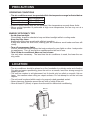
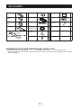
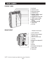
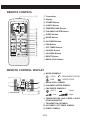
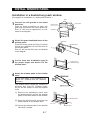
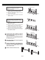
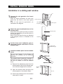
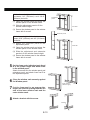
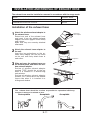
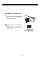
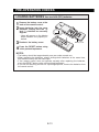
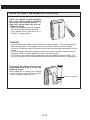
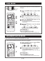
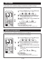
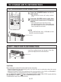
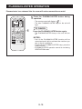
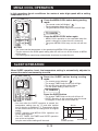
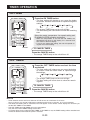
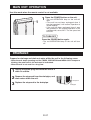
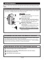
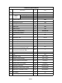
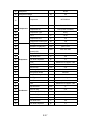
ENGLISH
PORTABLE TYPE
ROOM AIR CONDITIONER
INSTALLATION AND OPERATION
MANUAL
ESPAÑOL
CV-P10LJ
CV-P13LJ
ENGLISH
This manual explains the proper use of your new air conditioner. Please
read this manual carefully before using the product. This manual should
be kept in a safe place for handy reference.
CONTENTS
• USAGE CAUTIONS .....................................................................E-2
• PRECAUTIONS ......................................................................E-3
• LOCATION ...............................................................................E-3
• INCLUDED...............................................................................E-4
• PART NAMES ..........................................................................E-5
• INSTALL WINDOW PANEL......................................................E-7
• INSTALLATION AND REMOVAL OF EXHAUST HOSE .........E-11
• PRE-OPERATION CHECKS ...................................................E-13
• COOL MODE ...........................................................................E-15
• DEHUMIDIFICATION MODE ...................................................E-15
• FAN MODE ..............................................................................E-16
• VENTILATION MODE ..............................................................E-16
• TO CHANGE AIR FLOW DIRECTION .....................................E-17
• PLASMACLUSTER OPERATION ............................................E-18
• MEGA COOL OPERATION......................................................E-19
• SLEEP OPERATION................................................................E-19
• TIMER OPERATION ................................................................E-20
• MAIN UNIT OPERATION .........................................................E-21
• DRAINAGE ..............................................................................E-22
• MAINTENANCE .......................................................................E-22
• BEFORE CALLING FOR SERVICE ........................................E-23
E-1
USAGE CAUTIONS
• Ventilate the room periodically during use, especially if using gas appliances.
• Be sure to turn the unit off and disconnect the power supply cord before performing any maintenance or cleaning.
• Do not splash or pour water directly onto the unit.
Water can cause electrical shock or equipment damage.
• Remove the window panel and close the window in the event of particularly adverse weather.
Extremely adverse weather may cause water to leak in through the openings.
• To ensure proper drainage, the drainage hose must have no kinks or be on a different level during
dehumidification mode.
The drained water may spill out into the room.
• The temperature around the drainage hose must not be below freezing point when used.
Drained water may freeze inside the hose, causing water inside the unit to overflow into the room.
• Do not block the exhaust air outlet with obstacles. .
Cooling performance may be reduced or stop completely
NOTES ON OPERATION
• Allow 3 minutes for the compressor to restart cooling.
If you turn the air conditioner off and immediately restart it, allow three minutes for the compressor to restart
cooling. There is an electronic device in the unit that keeps the compressor turned off for three minutes for
safety.
• In the event of a power failure during use, allow 3 minutes before restarting the unit.
After power is reinstated, restart the air conditioner. If the power was off for less than three minutes, be sure
to wait at least three minutes before restarting the unit. If you restart the air conditioner within three minutes,
a protective device in the unit may cause the compressor to shut off. This protective device will prevent cooling for about 5 minutes. Any previous settings will be canceled and the unit will return to its initial settings.
• Low temperature operation: Is your unit freezing up?
Freezing may occur when the unit is set close to 18°C in low ambient temperature conditions, especially at
night.
In these conditions, a further temperature drop may cause the unit to freeze.
Setting the unit to a higher temperature will prevent it from freezing.
• Dehumidification mode increases room temperature.
The unit generates heat during dehumidification mode and the room temperature will rise. Warm air will be
blown out from the Exhaust air outlet, but this is normal and does not indicate a problem with the unit.
• This air conditioner blows the warm air generated by the unit outside the room via the exhaust hose
while in cool mode.
Accordingly, the same amount of air as that blown out will enter the room from outside through any
openings into the room.
• When cooling operation is performed at high humidity conditions, water tank inside the unit may frequently become full.
When water tank inside the unit is full, the unit stops operating and TIMER, OPERATION and MEGA COOL
lamps will blink. In this case, perform drainage to drain out water within the unit.
E-2
ENGLISH
• Drainage should be performed whenever moving the air conditioner.
If any water remains in the tank, it may spill out while being moved.
PRECAUTIONS
OPERATING CONDITIONS
• The air conditioner must be operated within the temperature range indicated below.
MODE
Room temperature
18°C ~ 35°C
Cool
15°C ~ 35°C
Dehumidification
• A built-in safety device may cut off operation if the temperature exceeds these limits.
• When cooling operation is performed at high room temperature, the fan may run at a
slower speed.
ENERGY EFFICIENCY TIPS
• Avoid direct sunlight.
Close blinds, drapes or shades to keep out direct sunlight while in cooling mode.
• Keep the filter clean.
Keeping the filter clean greatly aids efficient operation.
A dirty filter blocks the flow of air, making your air conditioner work harder and less efficiently.
• Turn off unnecessary lights.
Your air conditioner must remove the heat produced by your lights or other heat-producing appliances. Turn off any lights or appliances that are not in use.
• Turn off the air conditioner when no one is home.
Use only when necessary. The less time the air conditioner is used, the lower the running costs.
LOCATION
• The air conditioner should be placed on a firm foundation to minimize noise and vibration.
For safe and secure positioning, place the unit on a smooth, level floor strong enough to
support the unit.
• The unit has casters to aid placement, but it should only be rolled on smooth, flat surfaces. Use caution when rolling on carpet surfaces. Do not attempt to roll the unit over
objects.
• The unit must be placed within reach of a properly rated grounded socket.
• Never place any obstacles around the air inlet or outlet of the unit.
• Allow at least 12" (30cm) of space from the wall for efficient air-conditioning.
MIN.12"
(30cm)
MIN.12"
(30cm)
MIN.12"
(30cm)
E-3
INCLUDED
Exhaust hose
Manual
Rain guard
1
Window exhaust
adapter
1
Exhaust hose
adapter
1
1
Foam seal B
1 (adhesive type)
1
Extension panel
1
2
Insect guard net
1
Foam seal A
Bracket
Remote control
1
Battery
(AAA.1.5V)
2
1
3
Screw
8
SUGGESTED TOOLS FOR WINDOW PANEL INSTALLATION
1. Screwdriver(medium size Phillips)
2. Tape measure or ruler
3. Knife or scissors
4. Saw (In the event that the window panel needs to be cut down in size because the window is too narrow for
direct installation.)
E-4
PART NAMES
FRONT VIEW
1
1 Air Outlet
2
2 Vertical louvers
3
3 Horizontal louvers
4
4 POWER Button
5
5 Remote control signal
receiver window
6
7
8
9
0
0
REAR VIEW
6 OPERATION Lamp (red)
7 TIMER Lamp (orange)
8 MEGA COOL Lamp
(green)
9 PLASMACLUSTER
Lamp (blue)
0 Air inlet
Remote control hook
q
w
w Window exhaust adapter
e Exhaust hose
e
r
t
y
u
i
o
p
a
r Remote control hook
s
a Power plug
s Casters(4)
NOTE: Actual unit might vary slightly from above illustration.
E-5
q Insect guard net
t Air filter
y Exhaust hose adapter B
u Cover
i Grille
o Air inlet
p Drainpipe and stopcock
REMOTE CONTROL
1
1 Transmitter
2 Display
ENGLISH
3 POWER Button
4 LIGHTS Button
2
5 TEMPERATURE Button
3
4
5
6
7
8
9
0
q
w
e
r
t
6 PLASMACLUSTER Button
7 SLEEP Button
8 MODE Button
9 ON TIMER Button
0 FAN Button
q OFF TIMER Button
w CANCEL Button
e LOUVERS Button
r RESET Button
t MEGA COOL Button
REMOTE CONTROL DISPLAY
y MODE SYMBOLS
: COOL
: DEHUMIDIFICATION
y
: FAN
u
i
o
: VENTILATION
p
u MEGA COOL SYMBOL
i PLASMACLUSTER SYMBOL
a
o FAN SPEED SYMBOLS
: AUTO
: Quiet
: Low
: High
s
d
p TEMPERATURE AND TIMER COUNT
DOWN INDICATOR
a TRANSMITTING SYMBOL
s ON TIMER / OFF TIMER SYMBOL
d SLEEP SYMBOL
E-6
INSTALL WINDOW PANEL
Installation in a double-hung sash window
(See page 9 for installation in a sliding sash window. )
Hole
the rain guards to the insect
1 Connect
guard net.
Insert all three projections on each rain
guard into the holes in the insect guard net.
Side “A” will now be uppermost, as indicated in the diagram.
"A"
Projection
Attach the guard combined above to the
panel
2 window
Push the insect guard net firmly to ensure
that its four projections fit into the holes in
the window panel.
Side “A” will now be at the top, as indicated
in the diagram.
Rain guard
Insect guard
net
Projection
Window panel
"A"
Cut the foam seal A (adhesive type) to
proper length and attach it to the
3 the
window stool.
Foam seal A
(adhesive type)
Attach the window panel to the window
4 stool.
If the inner width of the window is between 22" (559mm) and 24" (609mm)
inclusive.
Cut
The window panel cannot be installed in
windows less than 22" (559mm) wide,
as you will be unable to shut the exhaust
cover.
(1) Remove the adjustment panel from
the window panel, and cut the window
panel to the same width as the window.
Window panel
(2) Open the window sash and place the
window panel on the window stool
22"~ 24"
(3) Secure the window panel to the window
stool with 2 screws.
E-7
Window stool
Adjustment panel
If the inner width of the window is
between 24" (609mm) and 36.8"
(934mm) inclusive.
(1) Open the window sash and place the
window panel on the window stool.
(2) Slide the adjustment panel to fit the
window frame width.
24"~36.8"
(3) Secure the window panel to the stool
with 3 screws.
If the inner width of the window is between 36.8" (934mm) and 48" (1219mm)
inclusive.
Extension panel
(1) Attach the extension panel to the
adjustment panel.
(2) Open the window sash and place the
window panel on the window stool.
(3) Slide the adjustment and extension
panels to fit the window frame width.
(4) Secure the window panel to the window
stool with 4 screws.
5
Cut the foam seals (adhesive type) A
and B to the proper length and attach it
to the window panel.
Attach foam seal A to the window panel and
extension panel, and attach foam seal B to
the adjustment panel.
36.8"~48"
Foam seal A
(adhesive type)
the window sash securely against
6 Close
the Window panel.
Cut the foam seal to an appropriate
7 length
and seal the opening between the
top of the inner window sash and the
outer window sash.
8 Attach a bracket with the screw.
Bracket
E-8
INSTALL WINDOW PANEL
Installation in a sliding sash window
"A"
the rain guards to the insect
1 Connect
guard net.
Insert all three projections on each rain
guard into the holes in the insect guard
net.
Side “A” will now be uppermost, as
indicated in the diagram.
Insect guard net
Hole
the guard combined above to the
window panel.
2 Attach
Push the insect guard net firmly to ensure
that its four projections fit into the holes in
the window panel.
Side “A” will now be at the top, as indicated
in the diagram, when it is installed in the
window.
Rain guard
Projection
Window panel
"A"
Projection
the foam seal A (adhesive type) to
the proper length and attach it to the
3 Cut
window frame.
Foam seal A
(adhesive type)
the window panel into the window
4 Install
frame.
If the inner height of the window is
between 22" (559mm) and 24" (609mm)
inclusive.
The window panel cannot be installed in
windows less than 22" (559mm) high, as
you will be unable to shut the exhaust
cover.
(1) Remove the adjustment panel from the
window panel, and cut the window panel to the same height as the window.
(2) Open the window sash and place the
window panel on the window frame.
(3) Secure the window panel to the window
frame with 2 screws.
E-9
Cut
Window
panel
22"~24"
If the inner height of the window is
between 24" (609mm) and 36.8"
(934mm) inclusive.
Adjustment
panel
(1) Open the window sash and place the
window panel on the window frame.
(2) Slide the adjustment panel to fit the
window frame height.
24"~36.8"
(3) Secure the window panel to the window
frame with 3 screws.
Extension panel
If the inner height of the window is between 36.8" (934mm) and 48" (1219mm)
inclusive.
(1) Attach the extension panel to the
adjustment panel.
36.8"~48"
(2) Open the window sash and place the
window panel on the window frame.
(3) Slide the adjustment and extension
panels to fit the window frame height.
(4) Secure the window panel to the window
frame with 4 screws.
the foam seals (adhesive type) A and
5 Cut
B to the proper length and attach them
to the window panel.
Attach foam seal A to the window panel and
extension panel, and attach foam seal B to
the adjustment panel.
the window sash securely against
6 Close
the Window panel.
Foam seal A
(adhesive type)
Cut the foam seal to an appropriate
and seal the opening between the
7 length
side of the inner window sash and the
outer window sash.
8 Attach a bracket with the screw.
Bracket
E-10
INSTALLATION AND REMOVAL OF EXHAUST HOSE
The exhaust hose must be installed or removed in accordance with the usage mode.
MODE
EXHAUST HOSE
COOL, FAN, VENTILATION, DEHUMIDIFICATION with no container
Install
DEHUMIDIFICATION with container
Remove
Installation of the exhaust hose
the window exhaust adapter to
1 Attach
the exhaust hose.
Extend one end of the exhaust hose
and insert it into the window exhaust
adapter, and turn it (approx. three times)
until it stops.
Make sure they are securely attached
afterwards.
Window exhaust adapter
Extend
Exhaust hose
the exhaust hose adapter to
2 Attach
the unit.
Insert the two projections on the exhaust hose adapter into the two holes
on the unit, and firmly attach them to
each other.
3
Projection
Hole
Slide and open the exhaust cover on
the window panel, and attach the window exhaust adapter.
Surface of window exhaust adapter
marked "TOP" should be at the top
when it is installed in a double-hung
sash window.
Surface of window exhaust adapter
marked "TOP" should be on the window
frame side when it is installed in a
sliding sash window.
"TOP"
The exhaust hose should be as short as possible for operational efficiency;
however, it must not be twisted or bent.
Unacceptable
Acceptable
E-11
Acceptable
Removal of the exhaust hose
Remove the window exhaust adapter.
1 Pull
out and remove the window exhaust
adapter by pushing down two “PUSH”
markings, and slide and close the exhaust
cover in the window panel.
"PUSH"
Remove the exhaust hose adapter from
2 the
unit.
Lift up and remove the exhaust hose
adapter from the unit by pushing down on
the two projections.
Projection
E-12
PRE-OPERATION CHECKS
LOADING BATTERIES Use two AAA (R03) batteries.
the battery cover at the
1 Remove
back of the remote control.
batteries into the com2 Insert
partment, making sure the ±
and — polarities are correctly
aligned.
• Lines will appear on the display
when batteries are properly installed.
3 Reattach the battery cover.
the RESET button using
4 Press
a thin pointed implement.
Battery cover
NOTES:
• The battery should last approximately one year under normal use.
• When replacing the batteries, always change both batteries at the same time,
and make sure they are the same type.
• If the remote control does not operate normally after replacing the batteries,
press the RESET button using a thin pointed implement.
• If you will not be using the unit for a prolonged period, remove the batteries from
the remote control.
E-13
HOW TO USE THE REMOTE CONTROL
ENGLISH
Point the remote control towards
the units signal receiver window
and press the desired button. A
beep will sound when the unit receives the signal.
• Make sure nothing, such as curtains,
blocks the signal receiver window.
• The remote control operates up to
23 feet (7 meters) away.
CAUTION
• Do not expose the signal receiver window to direct sunlight. This may adversely
affect its operation. If necessary, close the curtains to block out the sunlight.
• Use of a fluorescent lamp in the same room may interfere with transmission of the
signal.
• The unit may be affected by signals emitted from other remote controllers for televisions, VCRs or other equipment used in the same room.
• Do not leave the remote control exposed to direct sunlight or near a heater. Protect the remote control from moisture and shock which can discolor or damage it.
To prevent the remote control from
being misplaced, hook it to the unit
when not in use.
When attached, to remove the remote
control from the unit, lift the remote
control up slightly and pull it out.
Remote control hook
E-14
COOL MODE
Ensure that the stopcock is securely attached the
drainpipe.
Stopcock
Drainpipe
Press the MODE button to select COOL
1 mode.
COOL
2
3
1
4
DEHUM
FAN
VENT
Press the POWER button to start opera2 tion.
• The red OPERATION lamp on the unit will light.
Press the TEMPERATURE button to set
3 the
desired temperature.
• The temperature can be set within the range of
18°C to 30°C.
Press the FAN button to set the desired
4 fan
speed.
AUTO
QUIET
LOW
HIGH
TO TURN OFF
Press the POWER button again.
• The red OPERATION lamp on the unit will turn off.
DEHUMIDIFICATION MODE
In this mode, the air conditioner dehumidifies the room.
Ensure that the stopcock is securely attached the drainpipe.
Press the MODE button to select DEHU1 MIDIFICATION
mode.
COOL
2
1
DEHUM
FAN
VENT
2 Press the power button to start operation.
• The red OPERATION lamp on the unit will light.
• The temperature cannot be set.
• The fan speed is preset to AUTO and cannot be
changed.
TO TURN OFF
Press the POWER button again.
• The red OPERATION lamp on the unit will turn off.
E-15
FAN MODE
In this mode, the air conditioner simply circulates the air without cooling it.
Ensure that the stopcock is securely attached to the drainpipe.
1 Press the MODE button to select FAN mode.
COOL
2
DEHUM
FAN
VENT
2 Press the POWER button to start operation.
Press the FAN button to set the desired fan
3 speed.
• The red OPERATION lamp on the unit will light.
• The temperature cannot be set.
1
3
QUIET
LOW
HIGH
TO TURN OFF
Press the POWER button again.
• The red OPERATION lamp on the unit will turn off.
VENTILATION MODE
In this mode, the air conditioner ventilates the air to outdoors.
Ensure that the stopcock is securely attached to the drainpipe.
1 Press the MODE button to select VENT mode.
COOL
DEHUM
FAN
VENT
Press the POWER button to start operation.
red OPERATION lamp on the unit will light.
2 2 •• The
The temperature cannot be set.
Press the FAN button to set the desired fan
3 speed.
1
3
• Although the louvers are closed and no air blows
out into the room, the external ventilation fan
speed changes.
QUIET
LOW
HIGH
TO TURN OFF
Press the POWER button again.
• The red OPERATION lamp on the unit will turn off.
E-16
TO CHANGE AIR FLOW DIRECTION
UP / DOWN AIR FLOW DIRECTION
Press the LOUVERS button on the re1 mote
control.
• The horizontal louvers will swing continuously.
1
2
the LOUVERS button again when
2 Press
the horizontal louvers are at the desired
position.
• The horizontal louvers will stop moving.
• The adjusted position will be memorized and
the same position will be set automatically
when operated the next time.
NOTE
• During VENTILATION mode, UP/DOWN air flow
direction cannot be changed.
Horizontal louvers
LEFT / RIGHT AIR FLOW DIRECTION
Hold the vertical louver as shown in the diagram and adjust the air flow direction.
Vertical louvers
CAUTION
Never attempt to adjust the horizontal louvers manually.
• Manual adjustment of the horizontal louvers can cause the unit to malfunction when the remote
control is used for adjustment.
• When the horizontal louvers are positioned at the lowest position in the COOL or DEHUMIDIFICATION mode for an extended period of time, condensation may result.
Do not adjust the vertical louvers to the extreme left or right in the COOL mode with the
fan speed set to "QUIET ( )" for an extended period of time.
Condensation may form on the louvers.
E-17
PLASMACLUSTER OPERATION
Plasmacluster ions released into the room will reduce some airborne mold.
Press the PLASMACLUSTER button during
1 operation.
”.
• The blue PLASMACLUSTER lamp on the unit will
light.
TO CANCEL
1
Press the PLASMACLUSTER button again.
• The PLASMACLUSTER lamp on the unit will turn
off.
NOTES:
• Use of the PLASMACLUSTER function will be
memorized and it will be activated the next time you
turn on the air conditioner.
• To turn off the PLASMACLUSTER Lamp, press the
LIGHTS button.
• PLASMACLUSTER operation cannot be set during
VENTILATION mode.
E-18
ENGLISH
• The remote control will display “
MEGA COOL OPERATION
In this operation, the air conditioner fan works at extra high speed with a setting
temperature of 15°C.
Press the MEGA COOL button during cooling
1 mode.
• The remote control will display "
".
• The temperature display will go off.
• The green MEGA COOL lamp on the unit will light.
TO CANCEL
Press the MEGA COOL button again.
1
• MEGA COOL operation is also cancelled when the
mode is changed, or when the unit is turned off.
• The green MEGA COOL lamp on the unit will turn
off.
NOTES:
• You cannot set the temperature or fan speed during MEGA COOL operation.
• The fan returns to the HIGH speed setting after the unit has run for 30 minutes in MEGA
COOL mode.
• The extra high fan speed may automatically slow down to protect the unit.
SLEEP OPERATION
When SLEEP operation is set, the temperature setting is automatically adjusted to
prevent the room from becoming too cold.
Press the SLEEP button during cooling
1 mode.
•
•
•
•
”.
The remote control displays “
The orange TIMER lamp on the unit will light.
The unit will stop operating after 8 hours.
The fan speed setting is set to AUTO.
TO CANCEL
1
NOTES:
Press the SLEEP button.
• The orange TIMER lamp on the unit will turn off.
• SLEEP operation is also cancelled when the mode
is changed, or when the unit is turned off.
• One hour after the SLEEP operation is started, the
temperature setting rises by 1˚C and after another
hour it rises by an additional 1˚C. Temperature display
on the remote control will not change from its original
setting.
• SLEEP operation and MEGA COOL operation can
not be used together.
• The OFF TIMER, ON TIMER and SLEEP operation
can not be set together.
Only the most recent settings will be used.
E-19
8hours
1hour 1hour
1˚C
1˚C
Start of
SLEEP operation
Unit shuts off
TIMER OPERATION
ON TIMER
1 Press the ON TIMER button.
• The orange TIMER lamp on the unit will light.
• The time setting will count down to show the remaining
time.
1
CANCEL
Select the mode, temperature, fan speed setting and
PLASMACLUSTER operation as desired.
• When the temperature is set with the ON TIMER, the
temperature will show in the display for 5 seconds and
then return to the time display.
• If you do not change the setting, the unit will operate using the most recent setting.
TO CANCEL TIMER
Press the CANCEL button.
• The orange TIMER lamp on the unit will turn off.
OFF TIMER
the OFF TIMER button and set the time
1 asPress
desired.
• The time setting will change as you press the button
as follows. Hold the button down to speed through
the settings.
0.5h 1.0h 1.5h
10h
11h 12h
• The orange TIMER lamp on the unit will light.
• The time setting will count down to show the remaining time.
TO CANCEL TIMER
the CANCEL button.
1 Press
• The orange TIMER lamp on the unit will turn off.
CANCEL
NOTES
• Timer duration can be set from a minimum of half an hour to a maximum of 12 hours.
Up to 9.5 hours, you can set in half-hour increments and from 10 to 12 hours, in 1-hour increments.
• The latest time setting will be memorized and will appear on the remote control display the next time you
set the OFF TIMER or ON TIMER.
• The OFF TIMER and ON TIMER can not be set together.
Only the most recent TIMER setting will be valid.
• If a power failure occurs while the OFF TIMER or ON TIMER is set, the TIMER setting will be cancelled and
will not be retrieved even after the power is restored.
E-20
ENGLISH
• The time setting will change as you press the button
as follows. Hold the button down to speed through the
settings.
0.5h 1.0h 1.5h
10h
11h 12h
MAIN UNIT OPERATION
Use this mode when the remote control is not available.
1
1 Press the POWER button on the unit.
• The red OPERATION lamp on the unit will
light.
• If the unit has not been unplugged since it
was last operated, it will resume operation at
its last settings.
• If the unit has been unplugged since it was
last operated, it will resume operation in the
cooling mode, set at 20˚C. The fan speed set
to AUTO.
TO TURN OFF
Press the POWER button again.
• The red OPERATION lamp on the unit will turn
off.
DRAINAGE
Prepare for drainage and drain out water within the unit in the following cases.
• When the unit stops operating and the TIMER, OPERATION and MEGA COOL lamps are
blinking, the water tank is full and need to be drained.
• When the unit is not used for a long time.
the power plug and move the unit to a
1 Unplug
drain or outside.
the stopcock from the drainpipe, and
2 Remove
drain water within the unit.
Stopcock
3 Replace the stopcock to the drainpipe.
E-21
Drainpipe
MAINTENANCE
Be sure to disconnect the power from the wall socket before performing any maintenance.
CLEANING THE FILTER
AIR FILTER
1 REMOVE THE FILTER
• Gently pull the filter handle to the right and
slide the filter out of the unit.
Air filter
2 CLEAN THE FILTER
Air inlet filter
• Use a vacuum cleaner to remove any dust. If
the filter is very dirty, wash it with detergent
and rinse carefully with clean water. Dry the
filter in the shade before reinstalling them.
3 REINSTALL THE FILTER
• Hold the filter handle and gently push the filter
back into place.
Never operate the unit without the filter. Doing
so may result in serious damage to the unit.
Grille
AIR INLET FILTER (For single-duct type)
Remove the grille and clean the air inlet filter
with a vacuum cleaner.
CLEANING THE UNIT AND THE REMOTE CONTROL
Wipe them with a soft, dry cloth or with a cloth moistened with a mild soap. Carefully remove
any residue by wiping with a damp cloth and dry completely.
Avoid splashing water onto the unit. Water can dangerously damage the electrical insulation.
Never use harsh chemicals or abrasive cleaners on any part of the unit. To avoid damaging
the unit, do not use hot water (120°F/50°C or hotter) when cleaning.
MAINTENANCE AFTER AIR CONDITIONER SEASON
1
Perform drainage to drain out water within the unit.
2
3
Operate the unit in the FAN or VENTILATION mode for about half a day to
thoroughly dry inside the unit.
Clean the filters, then reinstall them.
E-22
ENGLISH
If the filter is clogged with dust, the airflow will be reduced, resulting in poor cooling
performance. The filter should be cleaned every two weeks.
BEFORE CALLING FOR SERVICE
If the unit appears to be malfunctioning, check the following points before calling
for a service.
AIR CONDITIONER DOES NOT OPERATE AT ALL
• Is the unit plugged in or is the plug loose?
• Has the fuse blown or is the circuit breaker tripped?
• Did you restart the unit within 3 minutes of a power failure?
If the power was off for less than 3 minutes when, you restarted the air conditioner, a protective
device may cause the compressor to shut off, preventing cooling for about 5 minutes.
• Are the OPERATION, TIMER and MEGA COOL lamps blinking?
The water tank inside the unit is full. It must be drained.
• Check the power plug.
AIR CONDITIONER DOES NOT COOL PROPERLY
• Is it set to FAN, DEHUMIDIFICATION or VENTILATION mode?
Cooling does not take place in these modes. Change the MODE setting.
• Is the filter clogged with dust?
Clean the filter.
• Is the cooling coil frozen?
No air will blow out if the cooling coil is frozen.
Run the air conditioner in FAN mode with the fan speed set to "HIGH" until all ice dissipates.
• Is the temperature set properly?
• Is the window exposed to direct sunlight?
Close the curtains or blinds to minimize solar energy heating the room.
• Is the exhaust hose too long?
For efficient operation, make the hose as short as possible. The exhaust hose must not be twisted
or bent.
SOUNDS
• The unit may seem rather loud for the first 2 to 3 minutes when the unit is turned on. This is the
sound of the compressor starting-up and is perfectly normal.
• A soft, swishing noise can be heard immediately after the unit is turned on or off, and also during
operation. This is the sound of the refrigerant flowing inside the unit.
• A low buzzing noise is emitted when the unit is generating Plasmacluster ions.
• This air conditioner evaporates water condensed during cooling operation within the unit through
the exhaust air outlet. Although water flowing sound may be heard, this is normal.
• An audible gurgling sound may be heard when the unit is operated on a gently sloping
floor. Place the unit on a level floor.
TIMER DOES NOT WORK PROPERLY
• If a power failure occurs while the TIMER is set, the TIMER setting will be cancelled and will not
be retrieved even after the power is restored. This is normal for this unit.
THE UNIT FAILS TO REACT TO THE REMOTE CONTROL SIGNAL
• Check the batteries in the remote control. Replace if necessary.
• Try to send the signal again with the remote control pointed directly at the unit’s signal receiver
window.
• Check whether the remote control batteries are installed with the polarities properly aligned.
THE DISCHARGED AIR HAS AN ODOR
• Plasmacluster ion generator emit small traces of ozone which may produce an odor. These
ozone emissions are below safety levels.
E-23
Technical Specifications
Sr
Parameter
No
1
2
Unit
Model
Power
Supply
Value
CV-P10LJ
Rated Voltage
V~
220-240
Rated Frequency
Hz
50
Phases
1
3
Cooling Capacity
W
2930
4
Cooling Power Input
W
1100
5
Cooling Power Current
A
4.80
6
Rated Input
W
1250
7
Rated Current
A
5.80
8
Air Flow Volume(H/M/L)
3
m /h
350/260/180
9
Dehumidifying Volume
L/h
1
10
EER
W/W
2.66
11
Application Area
m2
14~20
12
Climate Type
13
Isolation
14
Moisture Protection
15
16
T1
I
IP24
Permissible Excessive Operating Pressure
for the Discharge Side
Permissible Excessive Operating Pressure
for the Suction Side
MPa
3.8
MPa
1
17
Throttling Method
Capillary
18
Fuse
A
3.15
19
Operation Temp
℃
16ºC~30ºC
20
Ambient Temp (Cooling)
℃
10ºC~35ºC
21
Sound Pressure Level (H/M/L)
dB (A)
56/54/52
22
Sound Power Level (H/M/L)
dB (A)
66/65/62
23
Dimension (WXHXD)
mm
500×830×450
24
Dimension of Carton Box (L/W/H)
mm
578x532x862
25
Dimension of Package (L/W/H)
mm
581x535x877
26
Net Weight
kg
41
27
Gross Weight
kg
48
E-24
28
Refrigerant
R410A
29
Refrigerant Charge
30
Compressor
31
Compressor Model
32
33
kg
LANDA COMPRESSOR
QXA-B102T130
Compressor Oil
Compressor
0.67
RB68EP
Compressor Type
Rotary
34
L.R.A.
A
19.00
35
Compressor RLA
A
3.90
36
Compressor Power Input
W
850
37
Fan Type
38
Diameter Length(DXL)
mm
φ227 X 109
39
Fan Motor Speed(H/ML)
r/min
950/750/500
40
Output of Fan Motor
W
40
41
Fan Motor RLA
A
0.46
Fan Motor Capacitor
μF
3.5
42
Evaporator
Centrifugal
43
Form
44
Pipe Diameter
mm
φ7
45
Row-fin Gap
mm
3-1.6
46
Coil Length (LXDXW)
mm
348.5 X38.1X286
47
Swing Motor Model
48
Output of Swing Motor
49
Fan Type
50
Fan Diameter
51
Form
52
Pipe Diameter
mm
φ7
Rows-fin Gap
mm
3-1.6
Coil Length (LXDXW)
mm
348.5X38.1X362
55
Fan Motor Speed
rpm
1130 / 1100 / 1000 / 850
56
Output of Fan Motor
W
50
57
Fan Motor RLA
A
0.48
58
Fan Motor Capacitor
μF
3.5
53
54
Condenser
Aluminum Fin-copper Tube
MP28GA
W
2
Centrifugal
mm
φ227 X 109
Aluminum Fin-copper Tube
E-25
Technical Specifications
Sr
No
1
2
Parameter
Unit
Model
Power
Supply
Value
CV-P13LJ
Rated Voltage
V~
220-240
Rated Frequency
Hz
50
Phases
1
3
Cooling Capacity
W
3550
4
Cooling Power Input
W
1360
5
Cooling Power Current
A
6.00
6
Rated Input
W
1550
7
Rated Current
A
7.20
8
Air Flow Volume(H/M/L)
3
m /h
350/260/180
9
Dehumidifying Volume
L/h
1
10
EER
W/W
2.61
11
Application Area
m2
18~24
12
Climate Type
13
Isolation
14
Moisture Protection
15
Permissible Excessive Operating
Pressure for the Discharge Side
MPa
3.8
16
Permissible Excessive Operating
Pressure for the Suction Side
MPa
1
17
Throttling Method
18
Fuse
A
3.15
19
Operation Temp
℃
16ºC~30ºC
20
Ambient Temp (Cooling)
℃
10ºC~35ºC
21
Sound Pressure Level (H/M/L)
dB (A)
57/55/53
22
Sound Power Level (H/M/L)
dB (A)
67/66/63
23
Dimension (WXHXD)
mm
500×830×450
24
Dimension of Carton Box (L/W/H)
mm
578x532x862
25
Dimension of Package (L/W/H)
mm
581x535x877
26
Net Weight
kg
43
27
Gross Weight
kg
50
T1
I
IP24
Capillary
E-26
28
Refrigerant
R410A
29
Refrigerant Charge
30
Compressor
31
Compressor Model
32
Compressor
kg
0.95
MITSUBISHI
RN125VHFMC
Compressor Oil
PVE(FV50S or similar)
33
Compressor Type
34
L.R.A.
A
23.00
35
Compressor RLA
A
4.70
36
Compressor Power Input
W
1030
37
Fan Type
38
Diameter Length(DXL)
mm
φ227 X 109
39
Fan Motor
Speed(H/ML)
r/min
950 / 800 / 600
40
Output of Fan Motor
W
40
41
Fan Motor RLA
A
0.46
Fan Motor Capacitor
μF
3.5
42
Evaporator
Rotary
Centrifugal
43
Form
44
Pipe Diameter
mm
φ7
45
Row-fin Gap
mm
3-1.6
46
Coil Length (LXDXW)
mm
47
Swing Motor Model
48
Output of Swing Motor
49
Fan Type
50
Fan Diameter
51
Form
52
Pipe Diameter
mm
φ7
Rows-fin Gap
mm
4-1.6
Coil Length (LXDXW)
mm
348.5X50.8X362
55
Fan Motor Speed
rpm
1130 / 1100 / 1000 / 850
56
Output of Fan Motor
W
50
57
Fan Motor RLA
A
0.48
58
Fan Motor Capacitor
μF
3.5
53
54
Condenser
Aluminum Fin-copper Tube
348.5
X38.1X286
MP28GA
W
2
Centrifugal
mm
φ227 X 109
Aluminum Fin-copper Tube
E-27
WARRANTY
Consumer Electronic Products
Congratulations on Your Purchase!
This Sharp product is warranted against faults in materials and manufacture for a period
of twelve (12) months from the date of original purchase. (excluding lamps and air filters. )
If service is required during the warranty period, please contact your nearest Sharp
Approved Service Centre. These repairs would be carried out at no charge to the
owner, subject to the conditions specified herein.
The owner is responsible for any transportation and insurance costs if the product has
to be returned for repair.
This warranty does not extend to accessories or defects or injuries caused by or resulting
from causes not attributable to faulty parts or the manufacture of the product, including
but not limited to, defect or injury caused by or resulting from misuse, abuse, neglect,
accidental damage, improper voltage, liquid spillage, vermin infestation, software, or
any alterations made to the product which are not authorised by Sharp.
Please retain your sales documentation, as this should be produced to validate a
warranty claim.
This warranty is in addition to and in no way limits, varies or excludes any express and
implied rights and remedies under any relevant legislation in the country of sale.
IMPORTANT
DO NOT RETURN THIS DOCUMENT TO SHARP
Model No.
Serial No.
Date of Purchase
Retailer
S
A HA
AB UST RP
1 N RA CO
Hu Hun 40 LIA RP
nt tin 003 P OR
in g
gw wo 03 TY. ATI
oo od 9 4 LIM ON
0
d
O
NS Driv 5 ITE F
D
W e
S
21
N HAR
48
59 EW P C
Pe Hu ZEA OR
nr go L PO
os J AN R
e, oh D AT
Au ns LI IO
ck ton MIT N
lan D E OF
d riv D
e
For your reference, please enter the particulars of your purchase
below and retain, with your purchase documentation.
0
03
EB
(F
m
or
f
SP
)
10
20
IMPORTANT NOTICE: This warranty applies only to products sold in Australia & New Zealand
SHARP
FOR LOCATION ENQUIRIES WITHIN
AUSTRALIA
REGARDING YOUR LOCAL
SHARP APPROVED SERVICE CENTRE
VISIT OUR WEBSITE AT
www.sharp.net.au
OR CALL SHARP CUSTOMER CARE
1300 135 022
(LOCAL CALL COST APPLY WITHIN AUSTRALIA)
SHARP CORPORATION OF AUSTRALIA PTY LTD
SHARP
FOR LOCATION ENQUIRIES WITHIN
NEW ZEALAND
REGARDING YOUR LOCAL
SHARP APPROVED SERVICE CENTRE
VISIT OUR WEBSITE AT
www.sharp.net.nz
CONTACT YOUR SELLING DEALER/RETAILER
OR CALL
SHARP CUSTOMER SERVICES
TELEPHONE: 09 573 0111
FACSIMILE: 09 573 0113
SHARP CORPORATION OF NEW ZEALAND LIMITED
SPform019 (FEB 2010)
SHARP CORPORATION OF AUSTRALIA PTY LTD
ABN 40 003 039 405
1 Huntingwood Drive HUNTINGWOOD NSW 2148
www.sharp.net.au
66129905937