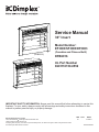
1
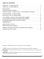
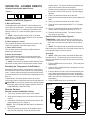
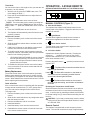
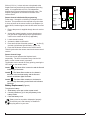
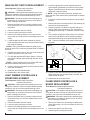
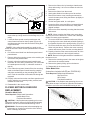
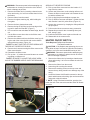
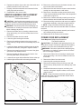
Service Manual
30” Insert
Model Number:
EF3003/SF3003/DF3003
(DFB6016)
(Canadian and Chinese Built)
DFB6016
UL Part Number
6901110159-0559
IMPORTANT SAFETY INFORMATION: Always read this manual first before attempting to service this
fireplace. For your safety, always comply with all warnings and safety instructions contained in this
manual to prevent personal injury or property damage.
Dimplex North America Limited
1367 Industrial Road Cambridge ON Canada N1R 7G8
1-888-346-7539 www.dimplex.com
In keeping with our policy of continuous product development, we reserve the right to make changes without notice.
© 2012 Dimplex North America Limited
REV
PCN
DATE
00
-
2-FEB-12
7400540000R00
TABLE OF CONTENTS
OPERATION - Acumen Remote. . . . . . . . . . . . . . . . . . . . . . . . . . . . . . . . . . . . . . . . 3
OPERATION - 3-Stage Remote. . . . . . . . . . . . . . . . . . . . . . . . . . . . . . . . . . . . . . . . 4
MAINTENANCE . . . . . . . . . . . . . . . . . . . . . . . . . . . . . . . . . . . . . . . . . . . . . . . . . . . . . . 6
EXPLODED PARTS DIAGRAM . . . . . . . . . . . . . . . . . . . . . . . . . . . . . . . . . . . . . . . . . . 7
WIRING DIAGRAM - Chinese Made - 3 Stage Remote Control. . . . . . . . . . 9
WIRING DIAGRAM - Canadian Made . . . . . . . . . . . . . . . . . . . . . . . . . . . . . . . . . . . 9
Main On/Off Switch Replacement. . . . . . . . . . . . . . . . . . . . . . . . . . . . . . . . . 10
Light Dimmer Controller & Board Replacement. . . . . . . . . . . . . . . . . . 10
Flame Speed Controller & Board Replacement. . . . . . . . . . . . . . . . . . . 10
Flicker Motor/Flicker Rod Replacement. . . . . . . . . . . . . . . . . . . . . . . . . . 11
Canadian Made Units. . . . . . . . . . . . . . . . . . . . . . . . . . . . . . . . . . . . . . . . . . . . . . . . . . . . . . . . . . . . . . . . . 11
China Made Units . . . . . . . . . . . . . . . . . . . . . . . . . . . . . . . . . . . . . . . . . . . . . . . . . . . . . . . . . . . . . . . . . . . . 11
Heater On/Off Switch . . . . . . . . . . . . . . . . . . . . . . . . . . . . . . . . . . . . . . . . . . . . 12
Power Cord Replacement. . . . . . . . . . . . . . . . . . . . . . . . . . . . . . . . . . . . . . . . 13
Remote Control Receiver/LED Harness Replacement. . . . . . . . . . . . . 14
TROUBLESHOOTING GUIDE . . . . . . . . . . . . . . . . . . . . . . . . . . . . . . . . . . . . . . . . . . 15
Always use a qualified technician or service agency to repair this fireplace.
! NOTE: Procedures and techniques that are considered important enough to emphasize.
CAUTION: Procedures and techniques which, if not carefully followed, will result in damage to the
equipment.
Warning: Procedures and techniques which, if not carefully followed, will expose the user to the
risk of fire, serious injury, or death.
2
www.dimplex.com
OPERATION - Acumen Remote
(EF3003/SF3003/DF3003 MOD 0-B Units)
Figure 1
MANUAL CONTROLS (Figure 1)
A. Main On/Off switch
The fireplace has a main ON/OFF switch located on the
control panel of the fireplace. To operate, press the switch
once to turn the unit on. A red light will illuminate to indicate the power is on. Press the switch again to turn the
unit off.
! NOTE: When the Main On/Off switch is used the
heater will run. The Main On/Off switch is to be used only
when the remote control is Off.
B. Flame brightness control
Turn the flame brightness control knob to increase or decrease the brightness of the flame and embers.
C. Flame action control
Turn the flame action control knob to adjust the flame
speed to the desired level.
D. Heater On/Off switch
When the Main On/Off switch is in the On position the
heater will run. Turn the Heater On/Off switch to the Off
position to shut off the heater.
! NOTE: Ensure that the Heater On/Off Switch is in the
On position for the heater to work with the remote control.
Resetting the Temperature Cutoff Switch
Should the heater overheat, an automatic cut out will turn
the fireplace off and it will not come back on without being
reset. It can be reset by switching the Main On/Off Switch
to Off and waiting five (5) minutes before switching the unit
back on.
If operating the unit with a remote control, the remote
control may require re-initializing after turning the power off.
CAUTION: If you need to continuously reset the heater,
disconnect power and call Dimplex customer service at
1-888-DIMPLEX (1-888-346-7539).
Remote Control
Remote Control Initialization & Setup
1. Turn on the electrical power at the circuit breaker.
2. Slide open the battery cover on the back of the remote
control.
3. Install three AAA batteries into the remote control. Replace the battery cover. (Figure 2)
! NOTE: The LCD display will flash when new batteries
are inserted.
4. Move the remote control close to the fireplace (less
than five feet preferred). Press any button on the
remote control. The remote control is transferring the
code to the receiver built into the fireplace.
5. Set the clock by pressing the button marked clock on
the remote control for five seconds. The hour display
will flash.
6. Use the up and down buttons to set the hour.
7. Press the clock button again and the minute display will
flash.
8. Use the up and down buttons to set the minute.
9. Press the clock button again and the °F or °C display
will flash.
10. Use the up and down buttons to select whether the
remote control will display temperature in °F or °C
11. Press the clock button again. The remote control is
now ready for operation.
Remote Control Operation (Figure 2)
arning: It takes some time for the receiver to reW
spond to the remote control. Do not press the buttons
more than once within two seconds for correct operation.
! NOTE: The fireplace has an automatic timer function
that will shut your fireplace off if the remote control has not
been operated within a six-hour period.
Auto Mode
! NOTE: When auto mode is activated the flame and
heat will turn on. The heater will turn on and off to keep
the room temperature the same as the remote control set
temperature.
1. Press POWER button to turn unit on. (There may be a
slight delay)
2. Press the UP or DOWN buttons to change the set temperature, if desired.
3. In auto mode the remote control will automatically turn
on the flame and heater when the room temperature
is below the target temperature and turn off the heater
ONLY when the room temperature is above the target
temperature.
4. Press POWER button once to turn unit off.
Figure 2
Room temperature
Remote display
up button
Down button
Set temperature
Time of day/Timer
Auto/off button
Timer button
Child Proof
Switch
Clock button
Batteries
Code selection switch
3
Timer Mode
You can set the timer to the length of time you want the unit
to operate (1 to 120 minutes).
1. With the unit Off, press the TIMER button once. The
timer display will blink “---”
2. Press the UP and DOWN buttons to adjust the timer
display in minutes.
3. Press the TIMER button once to set the timer.
! NOTE: The timer setting can be reset by pressing the
TIMER button and using the DOWN button until the timer
display reads “----”, press the TIMER button once to set the
timer.
4. Press the POWER button to turn the unit on.
5. The fireplace will automatically shut off when the timer
reaches 0 minutes.
Child Proof Function
1. Remove the battery cover on the back of the remote
control.
2. Slide the small blue switch down to activate the child
proof function.
3. Child Proof will appear on the display screen and all
function on the remote control will be locked.
4. To enable normal remote control operation when the
child proof function is activated, press the up and down
buttons in the following sequence:
• UP-DOWN-DOWN-UP-DOWN the remote functions
will now operate normally. The remote control will
return to the child proof function if buttons are not
pressed after two minutes.
5. To disable the child proof function remove the battery
cover on the back of the remote control and slide the
small blue switch up.
Battery Replacement
The remote control uses 3 AAA size batteries (included).
Replace these batteries at least every 6 months or when
the low battery icon appears on the remote control display
screen. When batteries are removed wait at least 1 minute
before replacing with new batteries.
Code selection
If the current remote control is interfering with the operation
of other remote control devices (TV, VCR, garage doors
etc.) The code can be changed on the remote control.
To change code:
1. Remove the battery cover on the back of the remote
control.
2. Slide the four small switches to any configuration other
than the factory set code.
3. Remove the batteries, wait for one minute.
4. Install the batteries.
5. Install the battery cover onto the remote control.
6. Reinitialize the remote control to match the new code
to the remote control receiver.
OPERATION - 3-Stage Remote
(EF3003/SF3003/DF3003 MOD C-E, All DFB6016 Units)
Figure 3
D
B
C
A
MANUAL CONTROLS (Figure 3)
A. Main On/Off Switch
The fireplace has a Main On/Off switch located on the
control panel of the fireplace. Toggle the switch to turn the
fireplace On and Off.
B.
Light Dimmer
Turn the flame brightness control knob to increase or
decrease the brightness of the flame and embers.
C.
Flame Action Control
Turn the flame action control knob to adjust the flame
speed to the desired level.
D. 3-Position Switch
Operates the electric fireplace manually. Pressing the
“ position) once turns on the electric
switch up (“
fireplace and activates Level 1, twice activates Level 2,
three times activates Level 3.
Pressing the switch down (“
fireplace OFF.
“ position) turns the electric
Level 1
: The flame effect is turned on and the first red
indicator light illuminates.
Level 2 : The flame effect remains on, the heater is
activated to the low heat setting, and the first and
second red indicator lights illuminate.
: The flame effect remains on, the heater is
Level 3
set to the high heat setting, and all three red indicators
illuminate.
Resetting the Temperature Cutoff Switch
Should the heater overheat, an automatic cut out will turn
the heater off and it will not come back on without being
reset. It can be reset by switching the Main On/Off Switch
to Off and waiting five (5) minutes before switching the unit
back on.
CAUTION: If you need to continuously reset the heater,
unplug the unit and call Dimplex North America Limited
at 1-888-346-7539.
Remote Control
The fireplace is supplied with a radio frequency remote
control. This remote control has a range of approximately
4
www.dimplex.com
50 feet (15.25 m). It does not have to be pointed at the
fireplace and can pass through most obstacles (including
walls). It is supplied with one of 2,178 independent
frequencies to prevent interference with other units. The
frequency designation is indicated on the back of the
remote control.
Remote Control Initialization/Reprogramming
Follow steps 1 through 6 to initialize your fireplace for the
first time. This procedure is also required every time there
is a loss of power to the remote control or the fireplace (i.e.
power failure, breaker tripped, main On/Off switch is turned
off).
1. Ensure that power is supplied through the main service
panel.
2. Access the manual controls, (remove glass doors or
pull grille down if applicable) pull the right side steel
curtain to the outside of the unit (if applicable).
3. Locate manual controls.
4. Activate the Main On/Off switch.
5. Press and hold the ON switch marked “
” for five (5)
seconds (red indicator light will flash). (Figure 1A)
6. Press the ON button located on the remote control.
This will synchronize the remote control and remote control
receiver.
Figure 4
On
Button
Off Button
Plastic
Strip
Battery
Cover
Remote Control Usage
The remote control operates the fireplace levels
sequentially. The level is increased every time the ON
button, on the remote control, is pressed.
The fireplace can be turned off at any point by pressing the
OFF button on the remote control.
Level 1
: The flame effect is turned on and the first red
indicator light illuminates.
Level 2 : The flame effect remains on, the heater is
activated to the low heat setting, and the first and
second red indicator lights illuminate.
Level 3
: The flame effect remains on, the heater is
set to the high heat setting, and all three red indicators
illuminate.
Battery Replacement (Figure 4)
To replace the battery:
1. Slide battery cover open on the remote control.
2. Correctly install one (1) 12 Volt (A23) battery in the
battery holder.
3. Close the battery cover.
Battery must be recycled or disposed of properly.
Check with your Local Authority or Retailer for
recycling advice in your area.
5
MAINTENANCE
WARNING: Disconnect power before attempting
any maintenance or cleaning to reduce the risk of fire,
electric shock or damage to persons.
CAUTION: Allow at least five (5) minutes for the light
bulbs to cool before touching them to avoid accidental
burning of the skin.
Light Bulb Replacement
Light bulbs need to be replaced when you notice a dark
section of the flame or when the clarity and detail of the
log exterior disappears. There are four (4) bulbs under the
log set which generate the flames and embers and two (2)
bulbs up, in behind the grille, that illuminate the interior of
the fireplace.
Required tools: Phillips #2 screw driver, Slot screw driver.
Approximate time: 15 minutes to change upper and lower
light bulbs.
Helpful Hints: It is a good idea to replace all light bulbs
at one time if they are close to the end of their rated life.
Group replacement will reduce the number of times you
need to open the unit to replace light bulbs.
To open the light bulb area:
1. Remove the trim by turning the retaining fasteners
counterclockwise 1/4 turn until the trim releases from
the firebox using a slotted screwdriver (Figure 5).
2. Hold the glass in place while removing the retaining clip
from the upper center of the firebox (Figure 6A, B).
3. Lift glass out and store in a safe place.
Lower Light Bulb Requirements
Quantity of four (4) clear chandelier or candelabra bulbs
with an E-12 (small) socket base, 60 Watt rating.
To replace the bottom light bulbs:
Figure 5
Figure 7
Back
Ledge
Rear
Tab
Figure 8
Log
Ember
bed
Side Section
1. Lift up the front edge of the log until it clears the front
tabs. Pull out until the rear tab clears the back ledge,
then lift out (Figure 7).
2. Examine the bulbs to determine which bulbs require
replacement.
3. Hold the socket while unscrewing the bulb.
4. Hold the socket while screwing in the new bulb.
5. Replace the log ember bed by placing the back lip of
the log ember bed under the partially reflective glass
then push the front of the log ember bed down into the
recess (Figure 7).
Upper Light Bulb Requirements
Quantity of two (2) clear chandelier or candelabra bulbs
with an E-12 (small) socket base, 15 Watt rating.
To replace the top light bulbs:
1. Locate the two upper bulbs inside the firebox at the top
(Figure 8).
2. Examine the bulbs to determine which bulbs require
replacement.
3. Hold the socket while unscrewing the bulb.
4. Hold the socket while screwing in the new bulb.
Glass Cleaning
The glass is cleaned in the factory during the assembly
operation. During shipment, installation, handling, etc., the
clear door may collect dust particles, these can be removed
by dusting lightly with a clean dry cloth.
To remove fingerprints or other marks, the clear door can
be cleaned with a damp cloth. The clear door should be
completely dried with a lint free cloth to prevent water
spots. To prevent scratching, do not use abrasive cleaners
or spray liquids on the clear door surface.
Figure 6
B
A
Holding
Glass
Retaining
Clip
Fireplace Surface Cleaning
Removing
Glass
Use a cloth dampened with warm water only to clean
painted surfaces of the electric fireplace. Do not use
abrasive cleaners.
6
www.dimplex.com
EXPLODED PARTS DIAGRAM
EF3003 MOD C-E, DFB6016
7
8
14
EF3003 MOD 0-B
11
24
10
9
16
12
13
7
2
3
21
20
4
5
18
22
1
6
25
26
15
23
7
Replacement Parts List
1
2
3
4
5
6
7
8
9
Part
Log Set
Grille Assembly
Heater Assembly
Upper Light
Harness (2-bulb)
Upper Light
Harness (Single)
Remote Control
Receiver
11
12
Remote Control
Dimmer Knob
13
Dimmer Control
15
16
17
18
19
20
21
22
23
24
25
26
27
NA
Canada
EF3003/
SF3003
Mod A
Flame Control
Knob
Flicker Motor
Flame Speed
Control
Power Cord
Partially Reflective Glass
Front Glass
Flame Panel
Decal, Side
Brick
Bushing Snap-In
Rotisserie
Grommet
Grommet
Flicker Rod
Assembly
Firebox Foot
DFB Trim Kit
China
EF3003/SF3003/DF3003
Mod 0 Mod A Mod B Mod C Mod D
2000230100RP
Mod E
DFB6016
Mod 0 Mod A Mod B Mod C
Mod D
0438550100RP
1009070159RP
2200490901RP comes with cutout 2300270300RP
2500080100RP
4200121000RP (2 Required)
2500190500RP
Lower Light
(comes with connectors,
Harness (4-bulb)
strip the ends)
On/Off Switch
Heater On/Off
Switch
LED & Switch
Remote
3000210400RP (Acumen)
Harness
10
14
EF3003/
SF3003
Mod 0
3000210100RP (Acumen)
3000211300RP (Acumen)
8800000800RP
Not Available - Can use
single pole wall dimmer
i.e. Leviton 6602-I
2500190500RP
2800070200RP
2800070500RP
3000430800RP 3000820500RP
(3 STAGE)
(3 STAGE)
3000430800RP
(3 STAGE)
3000820500RP
(3 STAGE)
3000370600RP (3 Stage, LED’s wired to Board)
8800000200RP
3000250100RP (Circuit Board and Potentiometer)
8800000200RP
2000150200RP
3000180300RP
(Potentiometer Only)
4100040400RP
5900300200RP
3000240200KIT
3000240100RP (Circuit Board and Potentiometer)
4100040500RP
5900300300RP
5900300400RP
5900310200RP
5900320100RP
7108890200RP
8500000400RP
8500000600RP
8500260003RP
5900080700RP
8800090100RP
8
6903430159RP
www.dimplex.com
WIRING DIAGRAM - Chinese Made - 3 Stage Remote Control
2 1
main On/Off
Switch
Remote Receiver
Board
Cord
P1
P2
N
L
Flame Speed
Controller
STEP mOTOR
Dimmer Control
Board
II
P2
I
momentary On
Switch
P1
upper Light harness
P
L
heater Assembly
Lower Light harness
Blower
heater
Element
WIRING DIAGRAM - Canadian Made
uPPER LIGhT ASSY
LOWER LIGhT ASSY
BLOWER ASSY
FAN
AC
mOT
DC
mOT
FLICkER
hEATER 1
CIRC BR
hEATER 2
LINE NEuTRAL
uPPER TAB
AC-DC ADJuST
LOWER TAB
DImmER
LOWER
mOTOR
SWITCh
ROCkER
uPPER
POTENTIOmETER
PCB
FAN1 L FAN2 N hEAT1 LhEAT2 N AC/N AC/L
L
N
AC CORD
mOmENTARY
SWITCh
LED
9
Main On/Off Switch Replacement
Tools Required: Phillips head Screwdriver
Flat Head Screwdriver
CAUTION: If the fireplace was operating prior to servicing allow at least 5 minutes for light bulbs and heating
element to cool off to avoid accidental burning of skin.
Warning: Disconnect power before attempting any
maintenance or cleaning to reduce the risk of electric
shock or damage to persons.
1. Remove the firebox trim by inserting a slotted screwdriver and turning ¼ of a turn to release the trim from
the firebox.
2. Remove the firebox from the mantel.
3. Lower the grille covering the controls.
4. Remove the retaining screws on the top cover and
remove the top, being careful not to damage any of the
wiring.
5. Locate the Main On/Off switch mounted on the top
panel and disconnect the wires and connections noting
their original locations.
! NOTE: Using a flat head screwdriver, gently pry between the ends of the connectors and the switch to release
the wires.
6. Depress the retainer clips on the rear of the switch and
push the switch out of the rear cover.
7. For units with attached LED light to Switch: Remove
the red LED indicator light out through the back of the
top panel.
! NOTE: Gently pressing on the front of the LED with a
flat head screwdriver will assist in removing it.
8. Properly orient the new switch and reconnect all of the
wires and connections.
9. Install the new LED indicator light.
10. Reassemble in the reverse order.
Light Dimmer Controller &
Board Replacement
Tools Required: Phillips head Screwdriver
Flat Head Screwdriver
CAUTION: If the fireplace was operating prior to servicing allow at least 5 minutes for light bulbs and heating
element to cool off to avoid accidental burning of skin.
Warning: Disconnect power before attempting any
maintenance or cleaning to reduce the risk of electric
shock or damage to persons.
1. Remove the firebox trim by inserting a slotted screwdriver and turning ¼ of a turn to release the trim from
the firebox.
2. Remove the firebox from the mantel.
3. Lower the grille covering the controls.
4. Remove the retaining screws on the top cover and
remove the top, being careful not to damage any of the
wiring.
5. Locate the light dimmer control potentiometer and
control board (if applicable) mounted on the top panel
(Figure 9) and disconnect the wires and connections
noting their original locations.
! NOTE: Using a flat head screwdriver, gently pry between the end of the wires and the potentiometer to release
the wires.
6. Pull off the control knob from the dimmer control potentiometer.
7. Remove either the mounting screws or the retaining nut
and remove the potentiometer.
8. Properly orient the new dimmer controller and reconnect all of the wiring connections. (For units made in
Canada proceed to step 11, otherwise continue to step
9.)
9. From under the top panel, break off the four mounting
studs on the light dimmer control board by grasping
with pliers and twisting on the protruding part of the
stud. Push the remainder of the studs out through the
top panel.
Figure 9
Potentiometer for Versions
made in Canada
10. Properly orient and mount the new Dimmer Control
Board, using the new mounting studs, provided, and
reattach all of the wires.
11. Reassemble in the reverse order.
Flame Speed Controller &
Board Replacement
Tools Required: Phillips head Screwdriver
Flat Head Screwdriver
CAUTION: If the fireplace was operating prior to servicing allow at least 5 minutes for light bulbs and heating
element to cool off to avoid accidental burning of skin.
Warning: Disconnect power before attempting any
maintenance or cleaning to reduce the risk of electric
shock or damage to persons.
1. Remove the firebox trim by inserting a slotted screwdriver and turning ¼ of a turn to release the trim from
the firebox.
2. Remove the firebox from the mantel.
3. Lower the grille covering the controls.
10
www.dimplex.com
Figure 10
Potentiometer for Versions
made in Canada
4. Remove the retaining screws on the top cover and
remove the top, being careful not to damage any of the
wiring.
5. Locate the flame speed control potentiometer and
control board mounted on the top panel (Figure 10)
and disconnect the wires and connections noting their
original locations.
! NOTE: Using a flat head screwdriver, gently pry between the end of the wires and the potentiometer to release
the wires.
6. Pull off the control knob from the flame speed control
potentiometer.
7. Remove either the mounting screws or the retaining nut
and remove the potentiometer.
8. Properly orient the new flame speed controller and
reconnect all of the wiring connections. (For units made
in Canada proceed to step 11, otherwise continue to
step 9.)
9. From under the top panel, break off the four mounting
studs on the flame speed control board by grasping
with pliers and twisting on the protruding part of the
stud. Push the remainder of the studs out through the
top panel.
10. Properly orient and mount the new flame speed control
board, using the new mounting studs, provided, and
reattach all of the wires.
11. Reassemble in the reverse order.
Flicker Motor/Flicker Rod
Replacement
1. Remove the firebox trim by inserting a slotted screwdriver and turning ¼ of a turn to release the trim from
the firebox.
2. Remove the firebox from the mantel.
3. Gently place firebox front side up on a flat surface.
4. Remove the bottom cover mounting screws and remove the bottom panel, lifting the bottom up slightly to
release the glass.
5. Set the front glass aside, in a safe place.
6. Locate the flicker motor and flicker rod assembly and
disconnect the wires and connections, noting their
original locations.
7. Remove the flicker assembly mounting bracket screws
and remove.
! NOTE: When removing the flicker motor some damage may occur to the flicker rod. If flicker rod is damaged
replace to ensure proper operation.
8. To remove the flicker rod attach needle nose pliers to
the spring on the motor shaft and pull while rotating in
the opposite direction of the spring winding. (Figure 11)
9. To remove the flicker motor you must first remove the
flicker rod (see above). Remove the motor mounting
screws and remove motor from the mounting bracket.
10. Properly orient the flicker motor and connect all of the
wires and connections in their original locations.
! NOTE: Removal of the glass eases the installation of
the bottom cover.
11. Remove the mounting screw in the center of the glass
and remove the retainer bracket.
12. Remove the glass by lifting up from the bottom.
13. Reassemble in the reverse order.
China Made Units
(Instructions included with RP part 7206780100)
Tools Required: Phillips head Screwdriver
Slip Joint Pliers
Wire Cutters
Flat Head Screwdriver
CAUTION: If the fireplace was operating prior to servicing allow at least 5 minutes for light bulbs and heating
element to cool off to avoid accidental burning of skin.
Figure 11
Canadian Made Units
Tools Required: Phillips head Screwdriver
Needle Nose Pliers
Flat Head Screwdriver
CAUTION: If the fireplace was operating prior to servicing allow at least 5 minutes for light bulbs and heating
element to cool off to avoid accidental burning of skin.
Warning: Disconnect power before attempting any
maintenance or cleaning to reduce the risk of electric
shock or damage to persons.
11
arning: Disconnect power before attempting any
W
maintenance or cleaning to reduce the risk of electric
shock or damage to persons.
1. Remove the firebox trim by inserting a slotted screwdriver and turning ¼ of a turn to release the trim from
the firebox.
2. Remove firebox from the mantel.
3. Remove front glass retaining clip, while holding the
front glass.
4. Remove the front glass and set aside.
5. Remove the log set by lifting up the front edge of the
log until it clears the front tabs. (Figure 7)
6. Pull out until the rear tab clears the back ledge, then lift
out.
7. Cut the flicker motor wires close to the flicker motor
end with wire cutters.
8. Remove the reflector rod from the flicker motor by pulling the end of the rod to the left and cut the reflector
spring with wire cutters. (Figure 12)
! NOTE: DO NOT TAKE THE LEFTOVER SPRING OFF
THE END OF THE REFLECTOR ROD.
9. Remove the 2 screws securing the flicker motor to the
flicker motor bracket.
10. Discard the old flicker motor.
11. Pick up the 1 ½” rubber sleeve and locate over remaining spring on reflector rod.
! NOTE: BE SURE TO LOCATE THE LARGE OPENING OF THE RUBBER SLEEVE OVER THE REMAINING
Figure 12
Remaining Spring
on Rod
SPRING OF THE REFLECTOR ROD.
12. Pick up new flicker motor and cut wire leads to 3 ½”
long with wire cutters.
13. Secure new flicker motor to the existing reflector rod.
Ensure the flicker motor bracket is in between the motor and the reflector rod.
14. Pick up slip joint pliers and adjust to proper slot.
15. Pick up 3M wire connector and place 1 yellow wire into
each terminal - total of 2 yellow wires. (Figure 13)
16. Secure wire connector by crimping the 3M symbol with
slip joint pliers.
17. Pull on end of wires to ensure a strong connection.
18. Repeat this process for the 4 remaining wires (red,
blue, orange, grey).
19. Install the new flicker motor in place of the old one.
20. Reassemble in the reverse order.
Heater On/Off Switch
Tools Required: Phillips head Screwdriver
Flat Head Screwdriver
CAUTION: If the fireplace was operating prior to servicing allow at least 5 minutes for light bulbs and heating
element to cool off to avoid accidental burning of skin.
Warning: Disconnect power before attempting any
maintenance or cleaning to reduce the risk of electric
shock or damage to persons.
1. Remove the firebox trim by inserting a slotted screwdriver and turning ¼ of a turn to release the trim from
the firebox.
2. Remove the firebox from the mantel.
3. Lower the grille covering the controls.
4. Remove the retaining screws on the top cover and
remove the top, being careful not to damage any of the
wiring.
5. Locate the Heater On/Off switch mounted on the top
panel and disconnect the wiring clips and connections
noting their original locations.
! NOTE: Using a flat head screwdriver, gently pry between the end of the connectors and the switch to release
the wires.
Figure 14
Figure 13
Ensure that all
connectors have
two wires with the
same color
12
www.dimplex.com
6. Depress the retainer clips on the rear of the switch and
push the switch out of the rear cover.
7. Properly orient the new switch and connect all of the
wiring clips and connections.
8. Reassemble in the reverse order.
Heater Assembly Replacement
Tools Required: Phillips head Screwdriver
Flat Head Screwdriver
CAUTION: If the fireplace was operating prior to servicing allow at least 5 minutes for light bulbs and heating
element to cool off to avoid accidental burning of skin.
Warning: Disconnect power before attempting any
maintenance or cleaning to reduce the risk of electric
shock or damage to persons.
1. Remove the firebox trim by inserting a slotted screwdriver and turning ¼ of a turn to release the trim from
the firebox.
2. Remove the firebox from the mantel.
3. Lower the grille covering the controls.
4. Remove the retaining screws on the top cover and
remove the top, being careful not to damage any of the
wiring.
5. Locate the heater assembly and disconnect the wiring
clips and connections, noting their original locations.
6. Remove the mounting screw in the center of the glass
and remove the retainer bracket.
7. Remove the glass by lifting up from the bottom. Set
the front glass aside, in a safe place.
8. Locate the two upper bulbs inside the firebox at the top.
9. Hold the light sockets while unscrewing the bulbs.
Figure 15
10. Remove the yellow wire from the heater element, coming from the heater on/off switch.
11. Remove the blue wire from the remote control receiver
coming from the temperature cutoff switch.
12. Remove the 2 element mounting screws from the top
of the element located on both sides of the temperature
cutoff switch. (Figure 15)
13. Remove the 4 heater assembly mounting screws from
inside the firebox and set aside the heater assembly.
14. Disconnect wiring connections and connect to replacement heater assembly, noting their original locations.
! NOTE: Using a flat head screwdriver gently pry between the end of the connectors and the heater to release
the wires.
15. Properly orient the new heater assembly and connect
any remaining wiring connections.
16. Reassemble in the reverse order as above.
Power Cord Replacement
Tools Required: Phillips head Screwdriver
Flat Head Screwdriver
CAUTION: If the fireplace was operating prior to servicing allow at least 5 minutes for light bulbs and heating
element to cool off to avoid accidental burning of skin.
Warning: Disconnect power before attempting any
maintenance or cleaning to reduce the risk of electric
shock or damage to persons.
1. Remove the firebox trim by inserting a slotted screwdriver and turning ¼ of a turn to release the trim from
the firebox.
2. Remove the firebox from the mantel.
3. Lower the grille covering the controls.
4. Remove the retaining screws on the top cover and
remove the top, being careful not to damage any of the
wiring.
5. Locate and disconnect the power cord wiring connections, noting their original locations on the remote
control receiver.
! NOTE: Using a flat head screwdriver gently pry between the end of the connectors and the remote control
receiver to release the wires.
Figure 16
13
6. With needle nose pliers grasp the power cord strain relief grommet from inside the rear panel and push while
twisting to remove.
7. Pull the power cord out through the hole in the rear
cover.
8. Install the new power cord through the hole in the rear
cover by placing the strain relief over the cord. Hold
the strain relief with pliers and slide into mounting hole.
9. Connect all of the wiring connections in their original
locations on the remote control receiver.
10. Reassemble in the reverse order.
tween the end of the connectors and the remote control
receiver to release the wires.
11. Depress the retainer clips on the rear of the 3-Position
Switch and push the switch out of the front of the top
panel.
12. Properly orient the new 3-Position Switch and reconnect all of the wires and connections.
13. Reassemble in the reverse order.
Figure 17
Remote Control Receiver/LED
Harness Replacement
Tools Required: Phillips head Screwdriver
Flat Head Screwdriver
CAUTION: If the fireplace was operating prior to servicing allow at least 5 minutes for light bulbs and heating
element to cool off to avoid accidental burning of skin.
Warning: Disconnect power before attempting any
maintenance or cleaning to reduce the risk of electric
shock or damage to persons.
1. Remove the firebox trim by inserting a slotted screwdriver and turning ¼ of a turn to release the trim from
the firebox.
2. Remove the firebox from the mantel.
3. Lower the grille covering the controls.
4. Remove the retaining screws on the top cover and
remove the top, being careful not to damage any of the
wiring.
5. Locate the remote control receiver, mounted on the top
panel, and disconnect the wiring clips and connections,
noting their original locations.
! NOTE: Using a flat head screwdriver gently pry between the end of the connectors and the remote control
receiver to release the wires.
6. From under the panel, break off the six mounting studs
on the remote control receiver by grasping with pliers
and twisting on the protruding part of the stud. Push
the remainder of the studs out through the top panel.
7. Properly orient and mount the new remote control
receiver, using the new mounting studs, provided, and
reconnect all of the wiring connections.
8. For units with attached LED lights: Pull the red LED
indicator lights out through the back of the top panel,
taking note of the sequence for reinstallation.
! NOTE: Gently pressing on the front of the LED with a
flat head screwdriver will assist in removing them.
9. Install the new LED indicator lights.
10. Locate the 3-Position Switch mounted on the top panel
and disconnect the wiring clips and connections noting
their original locations. (If required.)
! NOTE: Using a flat head screwdriver, gently pry be14
www.dimplex.com
TROUBLESHOOTING GUIDE
Problem
Cause
Solution
General
Circuit breaker trips or fuse
blows when unit is turned on
Short in unit wiring.
Trace wiring in unit.
Improper circuit current rating
Additional appliances may exceed the current rating
of the circuit breaker or fuse. Plug unit into another
outlet or install unit on a dedicated 15 amp circuit.
Unit turns on or off by itself
Remote control has a similar frequency
to other remotes in the area.
Change the frequency of the Remote Control, see
Operation Section.
Radio frequency disturbance from outside sources.
Change the frequency of the Remote Control, see Operation Section. If issues still persist, replace Remote
Control and Remote Control Receiver, where necessary. Initialize Remote Control with Receiver
Defective Remote Control Receiver
Replace Remote Control Receiver. Initialize with
Remote Control.
Lights dim in room while the unit
is on
Unit is drawing close to circuit current
rating
Move the unit to another outlet or install unit on a dedicated 15 amp circuit
Power cord gets warm
Normal Operation
The power cord may get slightly warm to the touch
when the heater is on
Defective power cord
Replace power cord if cord gets hot to the touch.
Appearance
Fireplace does not turn on Manu- Improper operation
ally
No incoming power from the electrical
wall socket
Fireplace does not turn on using
the Remote Control
Refer to Operation Section
Check Fuse/Breaker Panel
Loose wiring
Check wiring connections
Defective Switch (3-Position or On/Off)
Replace defective switch
Defective Remote Control Receiver
Replace Remote Control Receiver
Improper operation
Refer to Operation Section
Remote control not initialized to fireplace
Initialize the remote control
Remote Control not working properly
Install new battery into the Remote Control. Reinitialize remote control where necessary.
Replace Remote Control or Remote Control Receiver,
where necessary. Initialize Remote Control and
Receiver.
Flame Frozen
Defective Flicker Motor
Replace Flicker Motor
Defective Flame Speed Control
Replace Flame Speed Control Components
Loose wiring
Check wiring connections
Flame not bright or flame not
visible
Burnt out light bulbs
Replace out light bulbs
Loose wiring
Check wiring connections
Defective light harness
Replace light harness
Log set dim, not glowing
Burnt light bulbs
Replace light bulbs
Flame Shutter
Defective flicker motor
Replace flicker motor
Light leaking around the log set
Log set not positioned properly
Check log set for proper fit
15
Problem
Cause
Solution
Heater
Heater is not turning off
Heater is not turning on, but
flame effect is still functioning
Improper operation
Refer to Operation Section
Defective Heater On/Off Switch
Replace Heater On/Off Switch
Defective Remote Control Receiver
Replace Remote Control Receiver
Improper operation
Refer to Operation Section
Loose Wiring
Trace wiring in unit
Defective Heater On/Off switch
Replace Heater On/Off switch
Defective Heater assembly
Replace Heater assembly
Heater is turning off after a
couple of minutes of operation
Build up of dirt/dust in heater assembly
Ensure that exterior intake louvers and firebox cavity
are free of dirt/dust.
Defective Heater Assembly
Replace Heater Assembly
Heater emits an odor
Normal Operation
Normal operation is when the heater emits an odor
for a brief period after the heater is initially turned on.
The heater is burning off any dust accumulated during
manufacturing or operation.
Defective Heater Assembly
Replace Heater Assembly
Heater fan turns on but heater
lacks heat
Improper operation
Refer to Operation Section
Loose wiring
Trace wiring in unit
Defective Heater Assembly
Replace Heater Assembly
Heating element is glowing red
Normal Operation
Small glowing sections of the element are considered
normal.
Defective Heater Assembly
If larger glowing sections are causing the heater to trip
the thermal cutout, unplug unit, discontinue use and
replace heater assembly.
Excessive noise with the heater
on
Dirty Heater Assembly
Ensure that exterior intake louvers and firebox cavity
are free of dirt/dust.
Defective Heater Assembly
Replace Heater Assembly
Grinding or excessive noise with
the heater off
Flicker rod hitting or rubbing against
internal components
Ensure rod is straight and mounted properly in the
bracket, spinning freely away from other components.
Replace if necessary.
Defective Flicker Motor
Replace Flicker Motor
Defective Flame Speed Controller
Replace Flame Speed Controller
Noise
Buzzing noise from control panel
16
www.dimplex.com