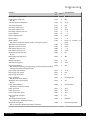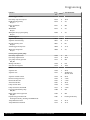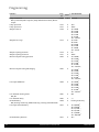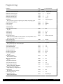
1
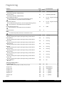
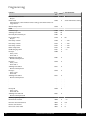
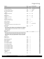
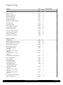
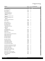
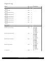
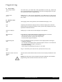
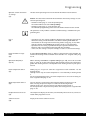
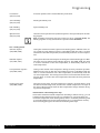
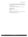
Table of contents
2
1.
1.1
1.2
1.3
1.4
About this manual...............................................................................................................................
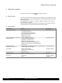
Manual contents.................................................................................................................................
Overview table....................................................................................................................................
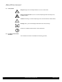
Used symbols......................................................................................................................................
For whom is this manual intended?.......................................................................................................
5
5
5
6
6
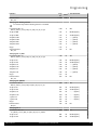
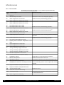
2.
2.1
2.2
2.3
2.4
2.5
2.6
Safety................................................................................................................................................
Usage according to purpose.................................................................................................................
General safety instructions...................................................................................................................
Regulations and standards...................................................................................................................
Liquid gas under ground.......................................................................................................................
CE-Marking.........................................................................................................................................
Conformity declaration........................................................................................................................
7
7
7
8
8
8
9
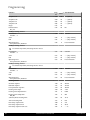
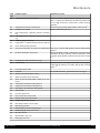
3.
3.1
3.2
3.3
3.4
Technical Data Paramount Three 30-115...............................................................................................
Dimensions and connections................................................................................................................
Specification.......................................................................................................................................
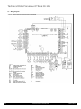
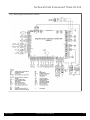
Wiring diagram...................................................................................................................................
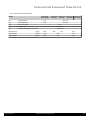
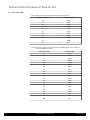
Sensor value tables..............................................................................................................................
10
10
12
14
16
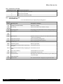
4.
4.1
4.2
4.3
4.4
4.5
4.6
4.7
4.8
Prior to installation.............................................................................................................................
Air Supply Openings............................................................................................................................
Corrosion protection............................................................................................................................
Requirements for heating circuit water.................................................................................................
Treating and preparing the heating water.............................................................................................
Practical notes for the heating contractor..............................................................................................
Notes for installation location..............................................................................................................
Application example............................................................................................................................
Legend...............................................................................................................................................
17
17
17
17
18
18
19
20
24
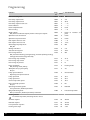
5.
5.1
5.2
5.3
5.4
5.5
5.6
5.7
5.8
5.9
5.10
5.11
5.12
5.13
5.14
5.15
5.16
5.17
Installation.........................................................................................................................................
Connecting heating circuit...................................................................................................................
Safety valve........................................................................................................................................
Condensate........................................................................................................................................
Sealing and filling of the plant..............................................................................................................
Flue gas connection.............................................................................................................................
Exhaust gas system.............................................................................................................................
Assembly of the exhaust gas system.....................................................................................................
Gas connection...................................................................................................................................
Check tightness...................................................................................................................................
Factory settings...................................................................................................................................
Supply pressure...................................................................................................................................
CO2 -Content......................................................................................................................................
Changing over from LPG to natural gas and vice versa.............................................................................
Gas valve............................................................................................................................................
Controller Stop Mode (Manual Adjustment of Burner Load).....................................................................
Guide Values for Injector Pressure.........................................................................................................
Electrical connection (general)..............................................................................................................
25
25
25
25
25
25
26
27
27
27
27
27
28
28
29
30
30
31
6.
6.1
6.2
6.3
6.4
6.5
Commissioning...................................................................................................................................
Menu-Commissioning.........................................................................................................................
Switching on.......................................................................................................................................
Temperatures for heating and domestic hot water.................................................................................
Individual time programme..................................................................................................................
Programming of necessary parameters..................................................................................................
33
33
33
34
34
34
Paramount three 30-115 kW
396532 07.11