1
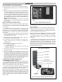
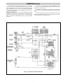
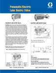
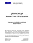
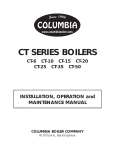
Installation, Operation
4
and
CHS
PQ404-6
(Supersedes PQ404-5)
RENEWAL PARTS IDENTIFICATION
161-048642-001
OCTOBER, 1983
Horizontal Electric Steam Boiler
Model Number CHS 0 – 150 PSI
Boiler Serial No . . . . . . . . . . . . . . . . . . . . . . . . . . . . . . . . . . . . . . . . . . . . Power Circuit Voltage . . . . . . . . . . . . . . . . . . . . . . . . . . . . . . . . . . . . . . . .
Model No. . . . . . . . . . . . . . . . . . . . . . . . . . . . . . . . . . . . . . . . . . . . . . . . . No. of Power Circuits . . . . . . . . . . . . . . . Amps. . . . . . . . . . . . . . . . . . . .
Electrical Capacity . . . . . . . . . . . . . . . . . . . . . . . . . . . . . . . . . . . . . . . . . . Control Circuit Voltage . . . . . . . . . . . . . . . . . . . . . . . . . . . . . . . . . . . . . . .
National Board No . . . . . . . . . . . . . . . . . . . . . . . . . . . . . . . . . . . . . . . . . . Total Amps . . . . . . . . . . . . . . . Phase . . . . . . . . . . . . Cy . . . . . . . . . . . . .
IMPORTANT – This data file contains the National Board Registration Certificate approving your generator. It must be kept near the generator at all times.
Specifications — 480 Volt Boilers*
CHS-360 Steam Boiler
150
5
50A 60A
30
1
300
4/0
181
CHS-180*
18.4
180
6
50A 60A
30
1
300
250
217
CHS-210*
21.4
210
7
50A 60A
30
1
600
600
253
CHS-240*
24.5
240
8
50A 60A
30
1
600
400
290
CHS-270*
27.6
270
9
50A 60A
30
1
600
600
326
CHS-300*
30.6
300
10
50A 60A
30
1
600
600
362
CHS-360
36.7
360
12
50A 60A
30
2
300
250
217
CHS-420
42.9
420
14
50A 60A
30
2
600
350
254
CHS-495
50.5
495
11
60A 100A
45
2
600
500
297
CHS-540
55.1
540
12
60A 100A
45
2
600
600
324
CHS-630
64.3
630
14
60A 100A
45
2
600
700
378
CHS-720
73.5
720
16
60A 100A
45
3
600
400
324
CHS-810
CHS-945
CHS-1080
CHS-1215
CHS-1350
CHS-1485
CHS-1620
82.7
96.4
110.0
124.0
138.0
152.0
165.0
810
945
1080
1215
1350
1485
1620
18
21
24
27
30
3
36
60A
60A
60A
60A
60A
60A
60A
45
45
45
45
45
45
45
3
3
4
4
5
5
6
600
600
600
600
600
600
600
600
700
500
700
600
700
600
324
378
324
378
324
378
324
100A
100A
100A
100A
100A
100A
100A
2
1
3
3
1
4
4
1
5
2
3
4
1
3
1
4
4
1
5
1
6
7
8
9
10
11
12
60
30
30
60
30
60
60
30
60
90
60
90
60
135
90
135
135
90
135
45
135
135
135
135
135
135
135
2 P’TROLS
15.3
452
543
633
723
3
P’TROLS
CHS-150*
Output
Standard Lbs. per
Elements Control
Hr. at
(kW)
System 212˚F
814
904
1085
1266
1492
1628
SEQUENCER
Model
Number
Power CC Size of
Nominal
90˚C
Amps
B.H.P.
Fuse Delta
Size
Wire
per
Rating kW Contactors Size kW
(Amps) (M.C.M) Circuit
1889
2170
2441
2848
3255
3662
4069
4476
4883
*150 kW Thru 300 kW Boilers available in 280V and 240V. Check Factory
INSTALLATION
CAUTION: To avoid electrical shock hazard, boilers
must be suitably grounded to earth.
NOTE: Chromalox boilers are pre-tested before shipment; no internal
piping or wiring is necessary. WARNING: Substitution of components or modification of wiring without prior consent of Chromalox,
Inc. voids warranty.
1. Locate unit on level floor or platform. NOTE: A minimum distance of 60 inches from wall, other equipment, etc. must be
allowed for removal of the elements.
2. Complete all piping to boiler. Connect water line to tagged fitting
on the motor and pump assembly, if used, or to tagged fitting on
water control feeder.
© 2010 Chromalox, Inc.
3. When any type of feed other than a pump feed is used – the existing water supply must be 10 pounds greater than the boiler operating pressure to assure water supply maintains proper water level in
boiler. Otherwise, lack of water can cause heater failure. Keep feed
water line valves open at all times.
4. All water feed systems are connected to supplied water inlet check
valve.
5. Connect steam line (with Globe valve) to boiler steam outlet. Valve
should be placed as close as possible to boiler outlet.
6. To insure maximum efficiency of supplied kw, all piping from outlet should be insulated.
7. Drain and relief valve piping should be in accordance with state
and local codes.
INSTALLATION (cont’d.)
High Pressure
Control
Pressure
Gauge
Manual Reset
Pressure Conrol
E
G
H
I
Safety Steam
Valve (G) Outlet (F)
Electric
Control
Box
Step Sequencer
(Optional)
Heating
Elements
A
60”
30”
Blow Down
Drain Valve
(L)
Wall
C
Blow Down
Drain Valve (L)
Water
Level
Control
Return
Inlet (J)
Wall
Check Valve
Water Inlet (K)
D
B
Figure 1
Figure 2
Figure 3
*CHS- thru 1620 have 2 control boxes (See Figure 2). Add 13” to “B” dimension.
A
B
C
D
E
F*
G
H
I
J
K
L
CHS-150 thru CHS-300
Model Number
57”
45”
32”
40”
68”
3” NPT
1”
25”
31”
2” NPT
1” NPT
1” NPT
CHS-360 thru CHS-420
57”
45”
32”
40”
68”
4”
1”
25”
31”
2” NPT
1” NPT
1” NPT
CHS-495 thru CHS-630
57”
45”
32”
47”
86”
4”
1”
34”
40”
2” NPT
1” NPT
1” NPT
CHS-720 thru CHS-810
76”
58”
45”
47”
94”
6”
1-1/2”
38”
44”
2” NPT
1” NPT
1” NPT
CHS-945 thru CHS-1080
76”
68”
45”
47”
94”
6”
1-1/2”
38”
44”
2” NPT
1” NPT
1” NPT
CHS-1215 thru CHS-1620
86”
76”
56”
50”
98”
6”
1-1/2”
40”
46”
2” NPT
1-1/2” NPT
1” NPT
*4” and 6” are flanged.
Typical Plumbing Installation of a Steam Boiler with Condensate Return System
Insulated Steam Lines
(Pitch Down 5˚)
Globe
Valve
Safety
Valve
Water/Steam
Separator
Heat
Gate Exchanger
Valve
Gate
Valve
(Typical Load)
Vacuum
Breaker
Check
Valve
Trap
Trap
Check Valve
Check Valve
Return
Pitch Down 5˚
Vent
Drain
Boiler
Auxiliary
Inlet
Cold Water
Make-Up
Condensate
Return
Cold Water
(for Initial Fill)
Drain
Centrifugal
Turbine Pump
2
Strainer
INSTALLATION (cont’d.)
SPECIAL INSTRUCTIONS FOR CUSTOMERS SUPPLYING
THEIR OWN CONDENSATE OR PUMP SYSTEMS.
1. Check the voltage of the motor before making the wiring connection. Some Chromalox boilers are supplied with dual voltage systems. The motor should always match the voltage of the control
circuit.
2. The motor circuit should be wired into the pump control as shown
in wiring diagram.
3. A heavy-duty vacuum breaker is required when condensate system
is used. (part number ES-89369)
L
1” Condensate
Return
1/2”
Water
Line
H
Strainers
1” Outlet
to Boiler
Width – 6-1/2
1” Drain
1” Discharge to Boiler
1/2” Water Line
1” Vent
Motor and
Pump
1/2” Solenoid
“W” Dimension – Overall Width
6-5/8”
5-7/8”
4-1/4”
3”
1/2” Strainer
7-1/4”
15-1/4” for CHS-150
16-3/8” for CHS-180 to 300
Model
Number
Max.
PSI
Tank Cap.
(Gal.)
L
H
W
CHS-150
thru
CHS-300
125
33
33-1/4
41-1/2
21
CHS-360
thru
CHS-420
150
40
40
41-1/2
21
Figure 4 – Motor and Pump Assembly
Figure 5 – Condensate Return System
WIRING
water cutoff to energize the shunt mechanism on the safety switch.
This is an additional safety feature that prevents a dangerous situation should a contactor or relay stick. Activation of the shunt trip
device will completely disconnect the boiler from the power supply. (See Figure 7).
3. Since boiler heating elements are susceptible to lightning damage,
plants not having lightning arresters that have above-ground electrical cable supply sources should install lightning arresters in the
proper size to meet the boiler kw load.
1. Wiring to boiler should be as per appropriate wiring diagram supplied with boiler and in accordance with Local and National
Electrical Codes.
2. SAFETY SWITCHES - Purchaser should use a safety switch
between his main power source and the boiler. The safety switch
should use circuit breakers or fuses and be in accordance with
NEC and local codes.
Serious thought should be given to the advisability of using a shunt
trip safety switch of the circuit breaker type as an additional safety precaution. It is possible to utilize the spare contacts in the low
To Aux.
L.W. C.O.
Shunt Trip Device
(Supplied by Others)
To L2 on
Terminal Strip
Hi-Limit
Pressuretrol
Operating
Pressuretrols
Common
To Field
Wiring
Input
Terminal
Supply
Voltage
To
L2
To Main
Switch
L.W.C.O. &
Pump Control
To Motor Starter
To Aux.
L.W.C.O.
*Standard on CHS-150 to CHS-300 units in lieu of step
sequencer and operating pressuretrol shown in Figure 8
Figure 6 – Pressuretrol Control System*
Figure 7 – Safety Switch (Field Installed)
3
WIRING (cont’d.)
Figure 8 – Typical Wiring Diagram
Power Circuit
Terminal Block
To
Power
Curcuit
Relay
Electronic Resistance
Sensing Amplifier for
Auxiliary Low Water Cutoff
To Other
Heater
Groups
120 Volt
Control Voltage
To
Other
Heater
Groups
Step
Sequencer
Low Water
Probe
Typical 3 Phase Heater Group
Figure 9 – Power Circuit Detail
Figure 10 – Auxiliary Low Water Cutoff
4
Hi Limit
Control
PRE-OPERATION CHECK
B. ADJUSTING OPERATING PRESSURE CONTROLS
1. Chromalox boilers are supplied with operating and high limit pressure controls. One is used for controlling the operating pressure of
the boiler while the other is used as a high limit control. To determine the difference in the controls, the high limit has a manual
reset lever on top of the case. Also, there is no differential scale
present.
2. On all controls, the pressure adjusting screw on the top of the case
sets the desired pressure. Turning the screw counterclockwise
reduces the pressure setting (see Figure 12). High limit control
should be set at 10 psig above the operating pressure of the boiler.
3. The differential adjusting screw on the operating control is set in
the same manner as the pressure adjusting screw. This scale setting, plus the main scale setting, equals cutout pressure of the operating control. (Scale A thru F equals 3 psi per letter. L9l B only)
L404A Differential is indicated on Scale Plate.
Cut-Off and
Alarm Switch
Pump
Low Water
Cut-Off
Terminals
Adjusting
Screws
Alarm
Circuit
Terminals
Pump
Circuit
Terminals
Line
Pump
Switch
Figure 11 – Automatic Reset Low Water Cutoff Junction Box
NOTES
1. Motor, Solenoid Valve and Dotted Control Wiring are included if
Motor and Pump package is supplied. Solenoid Valve only is supplied with 99117 Water feed.
2. 1/3 HP Motor is controlled directly without use of Motor Starter.
Differential
Adjusting
Screw
Differential
Setting
Indicator
Pressure
Setting
Indicator
After proper wiring and piping of boiler system is complete, testing of
controls can start. Before testing controls, it is recommended that all
contactor fusing be removed. This is to prevent possible element failure under test conditions.
CAUTION: Be sure all electrical connections are tight
before energizing boiler. Reset all manual reset controls by pushing reset buttons on: (1) high limit control
located on top of boiler and (2) McDonnell-Miller located on side of boiler.
A. McDONNELL & MILLER LOW WATER CUTOFF CONTROL OPERATION AND TESTING
1. Be sure all valves from incoming water supply are fully open. Turn
boiler switch to “ON” position, pump or solenoid valve will energize, allowing boiler to fill with water. Proper water level is automatically reached with level control supplied. Pump or solenoid
feed will shut off at proper water level. Contactor(s) will energize,
supplying power voltage to elements.
2. Checking operation of pump switch. (Figure 11) With water level
visible in sight glass, partially open drain valve at bottom of boiler. If automatic blowdown supplied, push manual blowdown
switch until valve open light is on, hold for few seconds. Water
level will fall, allowing float to trip pump switch to “ON” position.
Close drain valve or release manual blowdown switch. Pump
motor or solenoid valve will energize and water level will resume
to normal level in sight glass.
3. Checking low water cutout switch operation, open drain valve
completely. If automatic blowdown supplied, push in and hold
manual blowdown switch until water level falls enough to trip
cutout switch. Close drain valve or release manual blowdown
switch. If low water cutout is automatic reset, pump or solenoid
will return water level to normal. If low water cutout is manual
reset, then manual reset button on McDonnell & Miller low water
cutoff control must be pushed to complete circuit. Turn off boiler.
Reinstall contactor fuses.
Pressure
Adjusting
Screw
Operating Lever
Diaphragm Assembly
Mercury
Switch
Index Mark
Leveling
Indicator Pointer
Figure 12 – Pressure Control
To check operation of the controls, close steam outlet valve and
adjust operating pressure control to a low pressure setting. Also,
set high limit control at 10 psig above operating pressure control.
Turn on boiler and allow pressure to build up. When pressure
gauge reading approaches set point of pressure control, the switch
will trip and shut off boiler. Turn boiler main switch to “OFF".
To reset pressure control, bleed off enough pressure in the boiler
by opening steam outlet drain, or blowdown valve to allow the
operating control to reset.
4. HIGH LIMlT PRESSURE CONTROL OPERATION. The
high limit is tested in the same manner but with the operating control set above the pressure setting of the high limit. (Figure 13)
CAUTION: THIS IS FOR TEST PURPOSES ONLY!
When the high limit trips turn off boiler and reset high limit to
proper setting, the manual reset level must be pushed to resume
operation upon startup.
Pressure
Adjusting
Screw
Manual
Reset
Lever
Mercury
Switch
Scaleplate
Pressure
Setting
Indicator
Pump
For pump motors 1/2 h.p. Single Phase
or less, or D.C. 1/4 h.p. or less,
wire as main line switch.
Operating Lever
Diaphragm
Assembly
Leveling
Indicator
Index
Mark
Pointer
Line
Wiring Diagram – McDonnell & Miller Low Water Cutoff and Pump Control
Wiring Diagram – McDonnell & Miller Low Water Cutoff and Pump Control
5
OPERATION
RECOMMENDED START-UP PROCEDURES
1. Close globe valve on outlet side of boiler. (Customer Supplied)
2. Turn on boiler and allow pressure to build up to operating
pressure.
3. Only open globe valve by quarter turns at first, introducing smaller amounts of steam into process. Avoid opening globe valve all at
once. This will eliminate the possibility of evacuating the boiler of
water caused by the suddenly increased boiling of the water in the
vessel as the pressure is reduced. On boilers where constant pressure is not maintained, globe valve should be kept partially closed.
This will maintain a constant head on the boiler and stabilize any
fluctuation in boiler water level.
NOTE: For best boiler performance, a steam valve 1/4” smaller
than size of safety valve should be plumbed as close as practicable
to steam outlet.
Timer
Figure 14 – Automatic Blowdown Control Cabinet
MANUAL BLOWDOWN INSTRUCTIONS
Blowdown is an essential part of boiler operation. It is the best preventive maintenance you can give your boiler and will add years of life
to the unit. Make sure a blowdown schedule is established and followed regularly.
The unit may also be used to blow down boilers which run continuously, day and night.
INITIAL TESTING - Set the switch marked “Boiler Normal/24hour duty” located on the panel box to the “Boiler Normal” position.
In extremely hard water areas blowdown is necessary once a day.
In soft water areas, once each week. If there is a particular problem
which applies to your own local water condition other than mineral
content, take this into consideration in determining which schedule is
to be followed.
1. At the end of the working day, while boiler is still operating, turn
switch to the OFF position and close water supply valve. De-energize wall mounted safety switch.
On the large timer set the “ON” tab to 8 AM and the “OFF” tab to
8 PM. Set the small, time delay relay to “0".
Turn the larger timer by hand until the “ON” tab passes the “TIME
NOW” indicator so that the “TIME NOW” arrow indicates 10AM.
Energize the main feed to the “line terminals” of the unit. The
“boiler normal” pilot light as well as the “drain valve closed” light
should glow.
2. If blowing-down into a receptacle, allow pressure to decrease to
15-20 psi before opening blowdown valve.
Hold down the “drain” button for about six seconds. The “boiler
normal” light should go out immediately as well as the “drain valve
closed” light. It takes about 4 seconds for the drain valve to open fully
at which time the “drain valve open” light should light. As soon as the
“drain” button is released, the valve begins to close. When it reaches
the closed position, the “drain valve closed” light and the “boiler normal” light should light up again.
3. It is preferable to connect the blowdown valve directly into a
drainage system. If this is done, the boiler can be discharged at
operating pressure.
4. When discharge is complete and boiler is drained –
a. close the blowdown valve;
b. open water supply valve;
c. put boiler switch to the “ON” position; and, (d) close wall
mounted safety switch.
Pilot Lights and Switches
5. When refilling is complete turn off the boiler switch unless further
operation is desirable.
6. If you have been supplied with a Manual Reset Low Water control
as required in some states, the reset button on the control must be
pushed before boiler will begin developing pressure. (Do not push
reset until boiler has filled with water.) The use of chemical boiler
cleaning compounds in these boilers voids all warranties unless
approved by manufacturer. Some compounds will damage coppersheathed heating elements, thereby shortening their life.
Boiler Normal
AUTOMATIC BLOWDOWN INSTRUCTIONS
(IF FURNISHED) (See Figures 14 and 15)
The Automatic Blowdown is a device which automatically starts
up your boiler in the morning; shuts it down at night and blows down
(partially drains) the main boiler drain and the low water cut-off column for a predetermined time interval each working day.
Toggle Switch
Valve Open
Valve Closed
Manual Drain Push Button
Valve Actuator
The heart of the unit is an electrically operated straight through
type ball valve. It is specially designed to handle dirty, corrosive fluids
and particles without requiring cleaning or the use of a strainer.
Both the valve and the boiler are controlled by an electric control unit
which indicates with pilot lights when the drain valve is in the opened
or closed position and when the boiler is ON or OFF. In addition to the
automatic control function, the unit has a push button which momentarily de-energizes the boiler and opens the drain valve regardless of
the time of day.
Motor Drain
Ball Valve
Figure 15 – Display View of Automatic Blowdown Control Cabinet
6
OPERATION (cont’d.)
Set the tabs on the large timer for the ON and OFF times desired
for the boiler, screw in the small black day-skip tabs if the boiler is to
remain off for the weekend, etc.
Now turn the wheel on the large timer until the “off” tab passes the
“time now” arrow. The “boiler normal” light should go out and the
valve should begin to open. Once the “valve open” light goes on, the
valve should remain open for a few seconds and then automatically
close. The “drain valve closed” light should light and the “boiler normal” light should remain off.
If the boiler is on 24-hour duty set the OFF tab for the time that is
desired for blowdown. The ON tab can be ignored, but must remain on
timer.
NORMAL OPERATION – Set the “Boiler Normal/24-hour duty”
switch located on the inside of the control panel to “boiler normal” if
the boiler is to be shut down each night. Set it to “24-hour duty” if the
boiler is to remain on continuously 24 hours per day (except during
blowdown).
The small time delay relay controls the time that the drain valve
remains open. Counterclockwise decreases, clockwise increases blowdown time. Time must be adjusted by trial.
Figure 16 – Typical Wiring for Automatic Blowdown System
7
OPTIONAL EQUIPMENT FOR CHROMALOX STEAM BOILERS
“min” to “F”. The value of each division varies with the scale range of
the instrument.
AUXILIARY LOW WATER CUT-OFF
(See page 4 for Wiring Diagram)
Operation
Operation of this control is accomplished by sensing a minute AC
current flowing between submerged contact probe in the boiler shell.
Pressure
Scale Rating
0-15 psi
5-150 psi
When this minute AC current is conducted through an external circuit resistance up to 100,000 ohms or less, a signal of sufficient magnitude is present to trigger the SCR and, in turn, energize the control
relay.
Value Each
Division on Scale
2.2 psi
3.6 psi
Pressure scale rating will vary depending on pressure control supplied.
CHECKOUT
After the controller has been installed, wired, and set, it should be
tested with the system in operation. First allow the system to stabilize.
Then observe the operation of the controller while raising and lowering its set point. Pressure should increase when the set point is raised
and decrease when the set point is lowered. Use accurate pressure testing equipment when checking out the controller. Do not rely on inexpensive gauges. The controllers are carefully calibrated at the factory.
As the water level in the boiler drops below the level of the probe.
the AC circuit is broken and the control relay is de-energized. The control will not energize until sufficient water is present in the boiler.
Specifications
Input supply ....................120 vac/50-60 hz
Delectable Range............100.000 ohms
Probe Voltage..................24 vac
Probe Current..................10 milliamps
Control Relay ................Single pole double throw
If the motor or actuator runs in the proper direction when the set
point is adjusted, it can be assumed that the controller is operating
properly. If it runs in the wrong direction, reverse the B and W wires.
Observe the action of the motor to see if it stabilizes. If the motor is
moving constantly, widen the proportioning range a little at a time,
until the system is stable.
CAUTION: Control will not work with de-ionized or
demineralized water.
PROPORTIONING PRESSURE CONTROL (See Figure 17)
Typical Operation
Pressure variations cause the bellows to expand or contract.
Linkage between the bellows and the potentiometer wiper causes the
wiper to move across the windings on the potentiometer. This varies
the resistance between R and B, and between R and W, causing an
imbalance in the circuit connected to the controller.
Adjusting Screw
Differential
Adjusting Screw
A proportioning pressure control is used to regulate a motor driven
or solid state sequencer. The controller potentiometer, the feedback
potentiometer in the motor and a balancing relay in the motor form an
electric bridge circuit. As long as the pressure of the controlled medium remains at the set point of the controller, the circuit is balanced;
i.e., equal currents flow through both sides of the balancing relay and
the relay contacts are open. When the circuit is balanced, the motor
does not run.
R
If the pressure of the controlled medium rises, the wiper in the controller moves toward W. This unbalances the circuit, so a larger current
flows through one side of the balancing relay. The “close” contacts in
the relay make, causing the motor to drive toward its closed position.
As the motor runs, the wiper on the feedback potentiometer moves in
a direction balance, the balancing relay contacts open and the motor
stops.
W
B
Similarly, if the pressure of the controlled medium falls, the wiper
on the controller potentiometer moves toward B, and the “open” contacts in the balancing relay make. The motor drives toward its open
position until circuit balance is achieved.
Figure 17
(L91B) Proportioning Pressure Control Used with Sequencer Control
The slightest change in the pressure of the controlled medium will
cause a change in the number of elements energized to compensate for
it, thus keeping the pressure constant. This process is called modulation.
IF A CONTROLLER SEEMS
TO OPERATE IMPROPERLY (See Figure 18)
If the controller is suspected of operating improperly, it may be further
checked as follows.
PROPORTIONAL PRESSURE CONTROL ONLY
SUPPLIED WITH SEQUENCER
Main Setting - Turn the adjustment screw until the indicator is
opposite the low point of the desired throttling range. That is, if the
pressure is to be held to a minimum of 50 psi, set the indicator at 50
psi. The pressure will then be maintained between 50 psi and a higher
pressure equal to the 50 psi plus the throttling range.
1. Leave the controller installed where it is, but disconnect all power
to the controlled motor.
2. Loosen the cover screw below the main scaleplate and remove the
cover.
3. Disconnect the wires from the controller.
4. Connect an ohmmeter between controller terminals 8 and W to
measure the resistance of the potentiometer in the controller. The
ohmmeter should read about 135 ohms on an L91B.
THROTTLING RANGE SETTING L918
After setting the indicator for the minimum pressure, turn the throttling range adjustment screw until the throttling range indicator points
to the desired throttling range on the scale. This scale is graduated from
8
OPTIONAL EQUIPMENT FOR CHROMALOX STEAM BOILERS (cont’d.)
TESTING OPERATION OF SEQUENCER (See Figure 20)
1. With boiler off, remove wiring from pressure control on sequencer
low voltage terminal board.
2. Turn on boiler to supply the voltage to sequencer. Short terminal R
and B for counter-clockwise rotation and terminal R and W for
clockwise rotation.
3. If sequencer operates under this test procedure, but when rewired
to pressure controller, does not function, check pressure control.
Note that wiring is W-B and B-W-R-R between sequencer and
pressure control.
5. Connect the ohmmeter between controller terminals W and R and
raise the set point of the controller above the actual pressure being
measured. The ohmmeter should read the full value of the potentiometer measured in step 4 (135 ohms for an L91B).
6. Slowly lower the set point of the controller while observing the
ohmmeter reading. The resistance should drop to zero at some set
point below the actual pressure.
7. An approximation of the proportioning range can be made by
observing the change in set point required for a resistance change
from zero to full value.
8. When the controller is operating properly, reconnect the wires,
replace the cover. tighten the cover screw, and reset the controller
to the desired value.
9. Reconnect power to the controlled motor.
Main Scale
Adjusting Screw
Proportioning Range
Adjusting Screw
R
W
B
Main Scale
Setting
Indicator
Setpoint
Ohmmeter
W
R B
Increases
to 15 Ohms
Note: Terminals are not labeled, but screw-heads are
color-coded red (R), white (W) and blue (B).
Figure 18
BOILER SEQUENCER (5 STEP)
RECYCLE FEATURE (See Figure 19)
The step control is designed to drop out all contactors when control circuit is interrupted. On resumption of power, the camshaft rotates
to the counter-clockwise (ccw) limit, opening all the load switches.
The recycle relay then energizes, pulling in the load contact, and finally the camshaft rotates clockwise (cw) to the position called for by the
pressure controller energizing, in sequence, the required load stages.
Figure 20
Typical Wiring Diagram for 5 Step Motor Driven Sequencer
SEQUENCE REVERSER (See Figure 21)
GENERAL:
Sequence Reverser is an automatic switching device which is
interposed on an electric boiler between the proportional sequence
controller and the heating element contactors. The device is periodically actuated to alter the operating sequence of each of the heating
elements, thereby increasing the overall reliability of the boiler.
DETAILS:
The Sequence Reverser consists of an eight-day timer set up for
four days on and four days off which energizes and de-energizes double throw relays which are wired to reverse the “firing” order of the
heating element contactors with each operation of the timer.
Figure 19 – Five Step Sequencer
9
OPTIONAL EQUIPMENT FOR CHROMALOX STEAM BOILERS (cont’d.)
Solid State Progressive Sequencer (See Figure 22)
The solid state progressive sequencer provides accurate electronic
control of multi-stage loads of the type used in Chromalox steam boilers. It features progressive sequencing (first on-first off) which equalizes the operating time of each load. This control gives visual indication of each energized stage by means of integral solid state light emitting diodes. In the event of power interruption all heating elements are
immediately de-energized for safety. When power resumes, the control
will re-stage the loads one at a time. Refer to the diagram for visual
description of progressive sequencing.
PROGRESSIVE SEQUENCING
The Sequence Reverser accomplishes its tasks and shows the relative use of each of ten beat stages during the first four days of the
cycle. This is how the work load would be distributed on a boiler without Sequence Reverser. It can be seen the early stages are ON most of
the time and the later stages are OFF most of the time, since they are
used only during heat load peaks. (This analysis assumes hours of use
directly affecting component life. Frequency of on/off operations has
been ignored because of the limited in-rush associated with beating
elements and because of the relative independence of contactor life on
number of operations in the resistive load situations.)
It is clear, without sequence reversing, the early stages would tend
to fail long before the later stages. The sequence reverser essentially
equalizes the relative usages of heating stages. It can be seen, without
the sequence reverser the first heat stage is used approximately twice
as much as it is with the sequence reverser. This means the boiler will
be likely to have its first element failure in half the time without
The solid state sequencer operates on 120 V AC/60 Hz and each
output is relay switched with a load rating of 125 VA at 120 VAC.
Figure 21 – Five Step Sequence Reverser
sequence reverser as compared to the boiler with sequence reverser. In
addition. boilers without sequence reverser will have many failures
spread over a long time while boilers with sequence reversing will
require element changes at roughly the same time. (See wiring diagram on Page 4).
Figure 22 – Solid State Sequencer
MAINTENANCE
4. A check for water or steam leaks should also be made and any
loose fittings immediately tightened.
5. If boiler is equipped with a Solid State Auxiliary Low Water
Cutoff, every four months the probe should be checked for
deposits and cleaned, if necessary. This is accomplished by removing the inspection plate, removing the probe (with a standard
sparkplug wrench) cleaning and replacing.
Note: The system will not operate if the boiler is using distilled,
demineralized or deionized water.
At the same time, one of the bottom heating elements should be
removed. If scale has begun to form, all elements should be
cleaned and boiler drained and flushed.
6. IMPORTANT: The Manufacturers' Data Report enclosed within
the instruction sheet is very important and must be put in a safe
place. You may be called upon to produce it by a State agency.
CAUTION: Hazard of electric shock. Disconnect all
power before working on boiler.
Chromalox Electric Steam Boilers are designed for years of trouble-free performance. To establish a good preventative maintenance
program, we suggest the building maintenance man or engineer familiarize himself with these simple rules:
1. The use of specific boiler cleaning compounds cannot be recommended. We do recommend that a reputable firm of water treatment engineers be consulted regarding conditioning boiler water.
Proper selection must be made of a compound to prevent damage
to copper sheath heating elements.
2. The sight glass should be checked daily to ensure the boiler has
adequate water.
3. A monthly inspection should be made of the internal wiring. All
electrical connections should be checked for lightness.
10
MAINTENANCE
2. On automatic feed units, close valve on incoming water line. Drain
boiler completely of water.
3. Open boiler door to expose heating element.
4. Disconnect wire (electric) leads connecting element to main power
system of boiler. Again note wire connections to facilitate reassembly. Proceed to remove (6) 5/16-18 bolts from flange.
5. Thoroughly clean boiler flange of all foreign material. Be certain
no part of old gasket remains on boiler flange.
6. Apply “Slic-Tite” Gasket Compound (or equal) to both surfaces of
new gasket supplied with replacement element. Proceed to install
element flange assembly with gasket between boiler flange and
clement flange. In doing this, be careful to align flange holes so
wire connection terminals on element assembly are in line with
previously disconnected wire leads to facilitate easy connections.
7. When all (6) flange bolts are tight, connect all wires to terminals.
Make certain wires are clean and bright to assure good electrical
contact and nuts on screws are firmly secured.
CAUTION: Bolts should be lightened 10 a torque of 22 ftlbs.
8. Open water valve so water supply can reach boiler feed mechanism.
9. Put main safety switch to “on” position.
10. Turn boiler switch to “on” position.
11. As boiler automatically refills, observe the new flange assembly
for possible leaks. If water is noticed, the bolts must be retightened.
Before doing this, turn the boiler off at the main fuse safety switch.
12. As boiler is heated to working pressure, check flange assembly
again for leaks.
CAUTION - Avoid use of chemical cleaning compounds.
Follow maintenance instructions.
INSTRUCTIONS FOR ELEMENT REPLACEMENT
CAUTION: Before installing your new elements, be sure the
McDonnell-Miller low-water cut-off is operating perfectly and the
float chamber and lower equalizer column are completely clear of
sludge or other foreign matter. (See Figure 23)
Failure to do this may cause the immediate burnout of the new elements.
All elements are thoroughly checked before shipment. The manufacturer cannot be responsible for burnouts caused by a faulty lowwater cut-off.
1” Steam Equalizing Pipe
Pump and low water control
Normal Boiler
Water Line
Cut-off Level is
arrow mark
Blowdown
Valve
1” Water equalizing pipe
Figure 23
The lower equalizer column can best be examined by breaking the
unions on either side and then visually and manually examining the
piping with your fingers or probes to see if it is clear and clean.
READ COMPLETELY BEFORE STARTING WORK
1. Disconnect boiler from electric power supply at main safety switch
or fuse panel. Then turn boiler switch to “off” position.
RENEWAL PARTS IDENTIFICATION
11
RENEWAL PARTS IDENTIFICATION (cont’d.)
AUTOMATIC FEED PUMP CONTROLLER
Bellows Base
Clamp Assembly
Junction Panel
3 Wire
Switch
Bellows Assembly
with Gasket
2 Wire
Switch
Bellows Base Clamp
and Bellows Assembly
Low Water Cutoff and Water Feed Controls
Description
Complete Assembly . . . . . . . . . . . . . . . . . . . . . . . . . . . . . . . . . . . . .
Complete Assembly (Manual Reset) . . . . . . . . . . . . . . . . . . . . . . . .
Complete Head Mechanism . . . . . . . . . . . . . . . . . . . . . . . . . . . . . . .
Complete Head Mechanism (Manual Reset) . . . . . . . . . . . . . . . . . .
Float and Rod . . . . . . . . . . . . . . . . . . . . . . . . . . . . . . . . . . . . . . . . . .
Head Gasket . . . . . . . . . . . . . . . . . . . . . . . . . . . . . . . . . . . . . . . . . . .
3 Wire Cut-Off and Alarm Switch . . . . . . . . . . . . . . . . . . . . . . . . . . .
3 Wire Cut-off and Alarm Switch (Manual Reset) . . . . . . . . . . . . . .
2 Wire Pump Switch . . . . . . . . . . . . . . . . . . . . . . . . . . . . . . . . . . . . .
Junction Panel . . . . . . . . . . . . . . . . . . . . . . . . . . . . . . . . . . . . . . . . . .
Bellows Base Clamp & Bellows Assembly . . . . . . . . . . . . . . . . . . . .
Bellows Base Clamp & Bellows Assembly (Manual Reset) . . . . . . .
Bellows Base Gasket . . . . . . . . . . . . . . . . . . . . . . . . . . . . . . . . . . . . .
Bellows Base Clamp Assembly . . . . . . . . . . . . . . . . . . . . . . . . . . . . .
Bellows Base Clamp Assembly (Manual Reset) . . . . . . . . . . . . . . . .
Bellows Assembly w/Gasket . . . . . . . . . . . . . . . . . . . . . . . . . . . . . . .
B-W Auxiliary Low Water Cut-off . . . . . . . . . . . . . . . . . . . . . . . . . . .
Heating Elements and Gaskets
Description
30kW, 3 ph, 240V . . . . . . . . . . . . . . . . . . . . . . . . . . . . . . . . . . . . . . .
30kW, 3 ph, 480V . . . . . . . . . . . . . . . . . . . . . . . . . . . . . . . . . . . . . . .
45kW, 3 ph, 480V . . . . . . . . . . . . . . . . . . . . . . . . . . . . . . . . . . . . . . .
45kW, 3 ph, 240V . . . . . . . . . . . . . . . . . . . . . . . . . . . . . . . . . . . . . . .
60kW, 3 ph, 240V . . . . . . . . . . . . . . . . . . . . . . . . . . . . . . . . . . . . . . .
60kW, 3 ph, 480V . . . . . . . . . . . . . . . . . . . . . . . . . . . . . . . . . . . . . . .
90kW, 3 ph, 480V . . . . . . . . . . . . . . . . . . . . . . . . . . . . . . . . . . . . . . .
135kW, 3 ph, 480V . . . . . . . . . . . . . . . . . . . . . . . . . . . . . . . . . . . . . .
Element Gasket . . . . . . . . . . . . . . . . . . . . . . . . . . . . . . . . . . . . . . . . .
Hand Hole Gasket . . . . . . . . . . . . . . . . . . . . . . . . . . . . . . . . . . . . . . .
Contactors and Contactor Parts
Description
Contactor (50 amp, 115V, 60 cy.) . . . . . . . . . . . . . . . . . . . . . . . . . . .
Contactor (50 amp, 240V, 60 cy.) . . . . . . . . . . . . . . . . . . . . . . . . . . .
Contactor (60 amp, 115V) . . . . . . . . . . . . . . . . . . . . . . . . . . . . . . . .
Contactor (75 amp, 115V, 60 cy.) . . . . . . . . . . . . . . . . . . . . . . . . . . .
Contactor (75 amp, 208/240V, 60 cy.) . . . . . . . . . . . . . . . . . . . . . . .
Relay PR 7AY, 115V . . . . . . . . . . . . . . . . . . . . . . . . . . . . . . . . . . . . .
Relay PR 7AY, 230V . . . . . . . . . . . . . . . . . . . . . . . . . . . . . . . . . . . . .
Terminal Blocks and Fuses
Description
Control Circuit Fuse and Block . . . . . . . . . . . . . . . . . . . . . . . . . . . . .
Fuse Block, Class “J” 100 amp . . . . . . . . . . . . . . . . . . . . . . . . . . . . .
Power Circuit Fuse, Class “J” 60 amp. . . . . . . . . . . . . . . . . . . . . . . .
Power Circuit Fuse, Class “J” 100 amp. . . . . . . . . . . . . . . . . . . . . . .
Valves and Gauges
Description
Pressure Gauge 3-1/2, 160# . . . . . . . . . . . . . . . . . . . . . . . . . . . . . . .
Gauge Glass Assembly . . . . . . . . . . . . . . . . . . . . . . . . . . . . . . . . . . .
Sight Glass . . . . . . . . . . . . . . . . . . . . . . . . . . . . . . . . . . . . . . . . . . . .
Safety Valve – 30#, 1” . . . . . . . . . . . . . . . . . . . . . . . . . . . . . . . . . . . .
Safety Valve – 125#, 1” . . . . . . . . . . . . . . . . . . . . . . . . . . . . . . . . . . .
Safety Valve – 150#, 1” . . . . . . . . . . . . . . . . . . . . . . . . . . . . . . . . . . .
Check Valve – 1” Spring Type . . . . . . . . . . . . . . . . . . . . . . . . . . . . . .
Safety Valve – 15#, 1 . . . . . . . . . . . . . . . . . . . . . . . . . . . . . . . . . . . .
Part Number
300-118538-013
300-118538-026
300-118538-027
300-118538-028
300-118538-029
300-118538-030
292-118665-003
292-118665-004
292-118665-002
300-118538-031
300-118538-032
300-118538-033
300-118538-034
300-118538-035
300-118538-036
300-118538-037
300-118538-038
Part Number
155-118524-040
155-118524-021
155-118524-041
155-118524-042
155-118524-026
155-118524-022
155-118524-023
155-118524-043
132-146012-002
132-118533-004
Part Number
072-118525-001
072-118525-002
072-118525-003
072-118525-005
072-118525-006
072-118525-008
072-118525-009
Part Number
129-118527-001
129-118527-003
128-118530-003
128-118530-004
Part Number
344-118529-024
347-118537-002
374-118537-009
344-118529-006
344-118529-020
344-118529-025
276-118536-003
344-118529-008
Sylphon Bellow
Assembly
(See picture)
Bellows Base Gasket
Head Gasket
Float and Rod
Condensate Return Systems
Description
Condensate Return System (Comp.) 1/2 H.P.
115V or 230V, 60 cy. (CHS-150) . . . . . . . . . . . . . . . . . . . . . . . . . .
Condensate Return System (Comp.) 3/4 H.P.
115V or 230V, 60 cy. (CHS-180 to CHS-300) . . . . . . . . . . . . . . . .
(For Boilers CHS-360 through CHS-1350 check factory)
Part Number
226-118656-002
226-118656-009
Pressure Controls and Sequencers
Description
Part Number
Pressure Control Complete . . . . . . . . . . . . . . . . . . . . . . . . . . . . . . . .
344-118529-010
Pressure Control Complete (Manual Reset) . . . . . . . . . . . . . . . . . . .
344-118529-011
Mercury Tube (Two Wire) . . . . . . . . . . . . . . . . . . . . . . . . . . . . . . . . .
292-118665-001
Pressure Control Type L91B, 0-150 . . . . . . . . . . . . . . . . . . . . . . . . .
344-118529-015
5 Step Proportional Sequencer . . . . . . . . . . . . . . . . . . . . . . . . . . . . .
300-118538-005
10 Step Proportional Sequencer . . . . . . . . . . . . . . . . . . . . . . . . . . . .
300-118538-008
Pressure COntrol Type L91B, 0-15 . . . . . . . . . . . . . . . . . . . . . . . . . .
334-118529-016
Parts for Condensate Systems – Hot Water Motors & Pumps
Description
Part Number
Impeller for Pump (192 or 3/4 H.P). . . . . . . . . . . . . . . . . . . . . . . . .
Parts for Condensate Return Systems
Description
Pumps and Motor, 1/2 H.P., 115 Volts or
230 Volts, 1 ph. (CHS-150) . . . . . . . . . . . . . . . . . . . . . . . . . . . . . .
Pump and Motor 3/4 H.P., 115 Volts or
230 Volts, 1 ph. (CHS-180 to 300) . . . . . . . . . . . . . . . . . . . . . .
Float Valve – 33 Gallon Tank (CHS-150 to 300 . . . . . . . . . . . . . . . .
Seal for Pump (CHS-150 to 300) . . . . . . . . . . . . . . . . . . . . . . . . . . .
(For Boilers CHS-360 through CHS-1350 check factory)
Vacuum Breaker . . . . . . . . . . . . . . . . . . . . . . . . . . . . . . . . . . . . . . . .
Limited Warranty:
Please refer to the Chromalox limited warranty applicable to this product at
http://www.chromalox.com/customer-service/policies/termsofsale.aspx.
2150 N. RULON WHITE BLVD., OGDEN, UT 84404
Phone: 1-800-368-2493
www.chromalox.com
266-118671-001
Part Number
226-118656-005
226-118656-006
226-118662-006
251-118657-002
300-118538-039