1
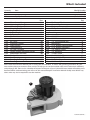
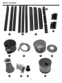
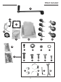
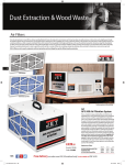
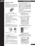
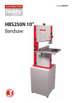
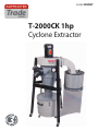
AXMINSTER Code 505087 Trade SERIES T-2000CK 1hp Cyclone Extractor Index of Contents Page No: Index of Contents 02 Declaration of Conformity 02 What’s Included 03-04-05 General Instructions for 230V Machines 06 Specific Safety for Dust Extractors 07 Specification07 Assembly Instructions 07-08-09-10-11-12-13 Overview Description 14-15 Operating and Adjustments 16 Maintenance17 Weekly LEV System Maintenance Log 18-19 LEV Testing 20 Parts Drawing/List 21-22-23 Wiring Diagram 24 Notes25 Declaration of Conformity Copied from CE Certificate Manufactured by Meta International Co., Ltd. is in compliance with the standards determined in the following Council Directive. The undersigned N. Sifonios, authorised by Meta International Co., Ltd No. 38-46, Ya Tan Road., Ta Ya Hsiang. Taichung Hisien, Taiwan, R.O.C. Low Voltage Directive: 2006/95/EC EN 60204-1: 2006+A1: 2009 Model Number: T-2000CK (DUST COLLECTOR) Warning Fully read manual and safety instructions before use Ear protection should be worn The symbols below advise that you follow the correct safety procedures when using this machine. Eye protection should be worn 2 Dust mask should be worn HAZARD Motor gets hot What’s Included Quantity Item Model Number T-2000CK 1 No (Code: 505087) 1hp Cyclone Extractor 1 No Motor Assembly 3 No Upper Leg Square Tubes 3 No Lower Leg Square Tubes 3 No Cross Support Brackets 3 No Leg Bracket Connectors 6 No Angled Brackets 1 No Extraction Drum 1 No Flexible Hose 1 No Bin 1 No Bin Cover 1 No Extraction Funnel 1 No Steel Ducting 1 No Inlet Moulding 1 No Air Filter Cartridge 1 No Shaker Paddle Operating Handle 1 No Manometer and Hose 1 No Bin Handle 1 No Steel Ducting 1 No Dust Bag Securing Clip 2 No Dust Bags Part 1 2 3 4 5 6 7 8 9 10 11 12 13 14 15 16 17 18 19 20 4 No Bin Castor Wheels 3 No Castor Wheels 3 No Bin Lever Clamps with Phillips Screws and Nuts Part 21 22 23 Bag Containing 24 12 No 12 No 8 No 6 No 6 No 56 No 2 No 6 No 1 No 2 No 2 No 1 No 1 No a b c d e f g h i j k l m 12 UNC Screws 5/16" Nuts 1/4" Domed Head Nuts M6 Washers 5/16" Button Head Hex Bolts 5/16" Button Head Bolts 1/4" Phillips Screws 1/4" Hex Bolts 12 UNC Screw Small Jubbile Clips Large Jubbile Clips 5mm Hex Key 10-12mm Spanner Please read the Instruction Manual prior to using your new machine. As well as the operating procedures for your new machine, there are numerous hints and tips to help you to use the machine safely and to maintain its efficiency and prolong its life. There is also a detailed description of the parts of your Cyclone Extractor, which will enable you to become familiar with terminology we will use in this manual. Keep this Instruction Manual readily accessible for any others who may also be required to use the machine. 1 3 Continues Over... What’s Included 5 6 2 3 7 11 4 8 12 9 10 14 13 4 What’s Included 15 17 18 16 19 20 21 22 23 a b e f c d 24 j g k 5 h l i m General Instruction for 230V Machines Good Working Practices/Safety or around a sharp edge. If the work you are carrying out is liable to generate flying grit, dust or chips, wear the appropriate safety clothing, goggles, gloves, masks etc. If the work operation appears to be excessively noisy, wear ear-defenders. If you wear your hair in a long style, wearing a cap, safety helmet, hairnet, even a sweatband, will minimise the possibility of your hair being caught up in the rotating parts of the machine, likewise, consideration should be given to the removal of rings and wristwatches if these are liable to be a ‘snag’ hazard. Consideration should also be given to non-slip footwear, etc. The following suggestions will enable you to observe good working practices, keep yourself and fellow workers safe and maintain your tools and equipment in good working order. WARNING!! KEEP TOOLS AND EQUIPMENT OUT OF THE REACH OF YOUNG CHILDREN Mains Powered Tools and Machines Primary Precautions These machines are supplied with a moulded 16 Amp plug and 3 core power cable. Before using the machine, inspect the cable and the plug to make sure that neither are damaged. If any damage is visible, have the damaged item inspected/repaired by a suitably qualified person. If it is necessary to replace the plug, it is preferable to use an ‘unbreakable’ type that will most resist damage. Only use a 16 Amp plug, and make sure the cable clamp is tightened securely. Fuse as required. If extension leads are to be used, carry out the same safety checks on them, and ensure that they are correctly rated to safely supply the current that is required for your machine. Remember, most machines or tools have handles or holding positions, the power cable is not one of them. Workplace/Environment Do not use this machine if you are tired, your attention is wandering or you are being subjected to distraction. Do not use this machine within the designated safety areas of flammable liquid stores or in areas where there may be volatile gases. There are very expensive, very specialised machines for working in these areas. Above all, OBSERVE…. make sure you know what is happening around you, and USE YOUR COMMON SENSE. Specific Safety for Dust Extractors Do not use this machine as a vacuum cleaner, try to keep the waste medium to wood by products. The machine is not designed for use outside. Keep the machine clean; it will enable you to more easily see any damage that may have occurred. Clean the machine with a damp soapy cloth if needs be, do not use any solvents or cleaners, as these may cause damage to any plastic parts or to the electrical components. It is good practice to leave the machine unplugged until work is about to commence, also make sure to unplug the machine when it is not in use, or unattended. To avoid inadvertent ‘start up’, if your machine is not fitted Do not uplift workshop floor debris (stones, nails, screws, paper etc., etc). Be aware that wood dust is an explosive medium. Do not allow any ‘naked light’ source to occur anywhere near the machine. This includes cigarettes, matches, etc, and do not place the machine near any unprotected light bulbs, that could possibly get broken. The suction force is generated by a high speed fan unit. This has the potential to amputate fingers, grab loose clothing (ties etc.,) and ‘bat’ large chips etc, at high speeds. Keep all guarding in place, and if access to the fan becomes necessary (due to blockage etc.,) disconnect the machine from the mains supply and ensure the fan has come to a complete stop before putting your hands anywhere near to it. Keep the work area as uncluttered as is practical, this includes personnel as well as material. Under no circumstances should CHILDREN be allowed in work areas. with a NVR system, ensure the switch is always returned to the OFF position. Once you are ready to commence work, remove any tools, objects or items that could inadvertently get ‘sucked up’ by the machine and place safely out of the way. Re-connect the machine, ensuring the power cable is not ‘snagged’ or routed where it could be tripped over as you move about the workshop; it is not too close to an unguarded heat source, or is laid over If you are not using ‘clear’ extraction hose, periodically remove the hose to check that the inlet to the machine is not getting restricted. (The safety guard grill of the inlet duct can be particularly irksome in this way, as long strand shavings etc., can wrap around the grill fret.) 6 Specific Safety for Dust Extractors Keep the particle filter clean. The machine relies on its ability to ‘blow’ air through the filter, to generate good suction. If the particle filter starts to clog, this reduces the air flow and hence the machine becomes less efficient. • If possible, try to connect everything together electrically, to eliminate static shocks. • Use the integral metal coil in flexible plastic hosing to connect units together. The particle filter can be cleaned, by removing the rear filter cover and using a vacuum cleaner, clean the inside of • Try to route the power cable and the hosing away from the filter. busy walkways. Be aware that in dry air periods or areas, the movement of • Do not allow the inlet to become ‘dead ended’, or block the air through the machine can generate static electric or restrict the outlet, this puts undue strain on the motor fields. These are not normally a problem as the machine and can lead to overheating. is bonded together via its construction and the whole is earthed back through the electrical supply; problems can occur with isolated items, such as stands or hosing that is insulated from the ground. Note: ALWAYS USE MANUFACTURERS Waste Bags WITH This Machine! Specification ModelT-2000CK RatingTrade Power 0.75 kW (230V, 1ph) Air Flow 1,100m³/hr Noise Level 80 dB @ 3m Filter Area 3.8m² Filtration 1 micron Particle Size 1 micron Hose Diameter 150mm x 1, 100mm x 2 Overall L x W x H 1,300 x 1,100 x 1,560mm Weight71kg Assembly Instructions Please read through the section entitled Parts Identification and Description, this will enable you to more readily identify those parts of the cyclone extractor. Please note: some of this assembly procedure is best accomplished by two persons. Although the tasks are not impossible, some of the items are heavy and awkward, and a mishandling error could cause injury. Please think about what you are doing, your capabilities and your personal safety. We have added the ‘two person symbol’ to any operation that we recommend should be a two person task. Unpack all the boxes and check all the components listed in the “What’s Included” section. If any parts or components are missing, please contact our Customer Services Department using the procedures and telephone numbers listed in our catalogue. Please note: on occasions the packing list is not strictly adhered to. Please check all the boxes, packets etc. to make sure that all the parts have been accounted for. PLEASE RECYCLE ANY UNWANTED PACKAGING RESPONSIBLY! 7 Assembly Instructions Step 2 Locate the three leg bracket connectors (5) and the lower leg square tubes (3), slide one of the connectors down into one of the leg tubes (3) and line up the lower two holes in the connector (5) with holes in the leg tube and secure in place with button head bolts (f ), see fig 04. Repeat the process as described above for the remaining leg tubes (3). Having unpacked the boxes, put all components where they are readily to hand. Locate the motor assemby (1), the upper and lower leg square tubes (2-3), cross support brackets (4), leg connectors (5), angle brackets (6), 5/16" button head Hex bolts (f ) and 5/16" nuts (b). Step 1 Place the motor assembly (1) upside down on the floor, locate the three upper leg square tubes (2), Note: one of them should have fixings for mounting the manometer (16). Line up the holes in the angled end of this square tube with the pre-drilled holes in the mounting plate next to the fan assembly outlet and secure using two button head bolts (f ) and 5mm Hex key (l), see figs 01-02-03. Repeat for the remaining leg supports. Repeat for the remaining square tubes (2). Fig 04 note: ONLY LIGHTLY TIGHTEN THE BOLT AT THIS STAGE! 5 Fig 01 3 Step 3 Insert the square tubes (3 and 5) down into the ends of each lower square tubes (2) and line up the holes, see figs 5-6. Mounting plate for the upper leg square tube (2 )with fixings for manometer (16) Fig 05 3 f Fig 02-03 5 1 2 Fig 06 3 f Holes for attaching angle brackets (6) 8 2 Assembly Instructions Step 4 Locate the angle brackets (6), place the bracket flat against the upper square tube (2), line up the pre-drilled holes and secure with two button head bolts (f ), see fig 07. Repeat on the process for the opposite side and carry on for the remaining legs. Fig 07 6 Locking Nut Step 7 Locate the extraction drum (7) and the 12unc Hex screws (a). Position the drum on top of the motor assembly (1), there are arrow marker labels on each unit, line up these labels and secure the drum (7) to the motor assembly (1) using the Hex screws (a). (see fig 12-13) 2 Fig 12-13 Step 5 Locate the three cross support brackets (4), line up the pre-drilled holes in one of the brackets with the holes in two of the angle brackets (6), using four button head bolts (f ) and nuts (b) secure the cross support bracket (4) in position. Repeat for the remaining two side of the assembly. (see figs 08-09). 7 Fig 08-09 b 1 4 Arrow marker label f a Step 6 Locate the three castor wheels (22), screw each castor into the threaded holes on top of legs (3), using a spanner tighen the nut at the base of each castor to lock the assembly in position. (see figs 10-11). Fig 10-11 Step 8 Loosen clamping bolt/nut from the extention funnel (11), remove the clamping ring and place safely aside. Lower the wide end of the funnel (11) on top of the drum (7) and line up the rims. Locate the clamping ring you removed earlier, position the ring over the rims and tighten the bolt/nut to lock both units (7-11) together. (see figs 14-15). 22 9 Continues Over... Assembly Instructions You will require the bin (9), bin castor wheels (21), bin lever clamps with Phillips screws and nuts (23), bin handle (17), 1/4" domed nuts (c), 1/4" Phillips screws (g), dust bag (20), flexible hose (8) and large jubilee clips (k). Fig 14-15 Step 10 Turn the bin (9) on its side and screw on the four castor wheels (21) into the threaded holes to the base of the bin and tighten the nuts using the supplied spanner (m), see fig 18. 11 Fig 18 9 Rim Clamping ring Step 9 Locate the bin cover (10), 1/4 " Hex bolts (h) and 1/4" domed head nuts (c). Place the bin cover (10) face up, on top of the funnel assembly (11). Line up the arrow marker labels and pre-drilled holes, place a Hex bolt (h) down through one of the holes and lightly secure with a domed head nut (c). (see figs 16-17) Repeat for the remaining holes then fully tighten. Step 11 Turn the bin (9) upright, locate the bin lever clamps (23) remove the four nuts and screws to one of the clamps and place safely aside. Line up the holes in the bin lever clamp (23) with the four holes to the side of the bin (9), (NOTE: make sure the lever clamp is the correct way round), replace the screws and nuts you removed earlier, securing the lever clamp in position. (see fig 19-20). Repeat the process for the remaining clamps. Fig 19-20 Fig 16-17 10 c 23 h 10 Assembly Instructions Step 14 Locate the dust bag (20), open the bag and place it inside the bin (9), see fig 25. (Make sure the bag is tucked over the edge of the bin) Step 12 Turn the cyclone assembly upright on its wheels, WARNING! the machine is heavy you are advised to seek help! Fig 25 locate the flexible hose (8) and the two Jubilee clips (k). Place a Jubilee clip over one end of the hose (8), introduce the hose over the bins inlet manifold and tighten the Jubilee clip, DON’T OVERTIGHTEN otherwise the hose will split, see fig 21. Insert the other Jubilee clip over the 20 Fig 21 k Step 15 Position the bin (9) beneath the bin cover (10), line up the bin lever latches (23) with the hooks on the bin cover (10), hook on the latches and press down the lever handles to raise the bin against the cover, making a tight seal, (see figs 26-27). 9 8 NOTE: you may need to adjust the nuts on lever latches if the seal between the cover and bin are not tight, see fig 27. other end of the hose and introduce it over the outlet manifold on the extraction funnel (11), secure in place, see fig 22. Fig 22 Fig 26-27 k 11 Step 13 Locate the bin handle (17), line up the holes with the two pre-drilled holes in the bin (9) and secure in place with 1/4" Phillips screws (g) and domed head nuts (c), see figs 23-24. Hook Latch Fig 23-24 17 Latch adjusing nuts c 11 Continues Over... Assembly Instructions You will require the steel ducting (12), steel ducting seal (18), 5/16" button head Hex bolts (e), 5/16" button head Hex bolt (f ), air filter cartridge (14) and shaker paddle handle (15). Step 18 Locate shaker paddle hande (15), loosen the grub screw to the side of the machined aperture using the supplied Hex key (l), slide the handle (15) onto the shaker paddle drive shaft, on top of the air filter (14) and nip up the grub screw to lock the handle in place, see figs 33-34. Step 16 Locate steel ducting (12), insert the ducting seal (18) into the square recess of the ducting (12), see fig 28. Fig 33-34 Fig 28 Machined aperture 18 12 l Grub screw 15 Place the square end of the ducting (12) over the outlet of the motor assembly (1), secure in place using eight button head Hex bolts (f ), see figs 29-30. Fig 29-30 12 f 1 Step 19 Locate the remaining dust bag (20) and dust bag securing clip (19). Open up the bag and rap it around the base of the air filter (14), see 35. Remove the securing clip (19) from its packaging, rap it around the filter (14) and dust bag (20) and secure the dust bag in place, see figs 35-36-37. Fig 35-36-37 Step 17 Locate the six button head Hex bolts (e), offer up the cut out slot in the air filter cartridge (14) with the rectangular outlet of the ducting (12). Line up the pre-drilled holes and secure both units together using six button head Hex bolts (e), see figs 31-32. 14 Fig 31-32 20 14 e 19 12 Assembly Instructions Step 20 Locate the manometer and hose (16), remove the fixings from the lower leg square tube (2), offer up the two pre-drilled holes in the manometer (16) with the holes in the leg (2), replace the fixing and tighten. (see fig 38) Step 23 Locate the inlet moulding (13) and the 12unc screw (i). Insert the moulding over the outlet manifold on the extraction funnel (11), line up the pre-drilled holes and secure using the 12unc screw and Phillips screw driver, see fig 41. Fig 41 note: make sure the manometer (16) is mounted to the left side of the leg! Fig 38 13 i 16 11 2 Step 24 Finally go round and make sure all fixings are tight and secure. Step 21 Place a small Jubilee (j) over one end of the hose and insert it over the small outlet manifold on the extraction funnel (11) and nip up tight, see fig 39. Testing the extractor WARNING!! make sure children are kept away from the cyclone extractor while in operation WARNING! dont overtighten the jubilee clip to prevent the hose from splitting! Fig 39 connect the power supply to the mains and switch on! j NOTE: Always turn on/off the extractor by the NVR control switch not the mains switch! Wait until it’s up to full speed and check for signs of vibration, if all is well.. switch off and wait until the extractor has come to a compleate stop! Hose disconnect the power supply from the mains! Step 22 Connect the other end of the hose to the inlet manifold to the rear of the manometer (16), see fig 40. Fig 40 If the extractor fails to start up or any other strang noises apart from vibraction sounds, contact the “Technical Sales” for support. Phone: 03332 406406 Email: [email protected] j 13 Overview Description NVR switch assembly 1 16 12 7 15 2 13 14 11 4 8 19 10 3 20 17 9 21 1 2 3 4 7 8 9 10 11 12 22 23 13 14 15 16 17 19 20 21 22 23 Motor Assembly Upper Leg Square Tube Lower Leg Square Tube Cross Support Bracket Extraction Drum Flexible Hose Bin Bin Cover Extraction Funnel Steel Ducting 14 Inlet Moulding Air Filter Cartridge Shaker Paddle Handle Manometer Bin Handle Dust Bag Securing Clip Dust Bag Bin Castor Wheel Castor Wheel Bin Lever Clamp Overview Description Off 23 On NVR switch assembly with (O) indicating (OFF) and (I) indicating (ON). For emergencies “SLAP” the shroud down to “STOP” the machine. Bin lever clamp (23), pull up the handle to release bin. 13 15 Inlet moulding (13), with lid Shaker handle lever (15), move this handle from side to side to remove dust build up from inside the air filter (14). 14 Shaker paddle drive shaft inner filter Air filter (14), shaker paddle assembly Bin (9) “FULL” indicator, empty the bin’s contents when it reaches the “FULL” mark. 15 Operating and Adjustments Levelling the Extractor Fig 43 If you find the extractor castors (22), is not in contact with the floor you can adjust them by loosening the locking nut beneath the castors pivot assembly then rotate each castor in turn, in or out until correct then retighten the locking nut to secure the castors (22) in position, see fig 42. Fig 42 indicating mark Switching ON/OFF Always turn on/off the extractor by the NVR control switch not the mains switch If you find the reading has increased there could be a blockage in the ducting system or extractor unit, check the following: WARNING!! Before carrying out any maintenance disconnect the cyclone extractor from the mains supply! Manometer The manometer is used to monitor the air flow in the ducting system. When you first use your extractor it is recommended you mark on the ‘manometer’ the pressure • Check the rear filter for signs of buildup of sawdust the extractor it running at. To do this, follow the and clean with a vacuum cleaner instructions below. • Check the hoses for blockages Note: the reading can vary depending on the size of the ducting system. • Check the bin bag and empty if full 1. Connect your cyclone extractor to the ducting system. If the reading has decreased, check the following: •Check the hoses are secure, ‘NOT LOOSE’ which will lead to air leakages • Check hoses for splits and cracks • Check “Blastgates” that are not in use are shut Extraction Accessories 2. Start up the extractor by pressing the ‘green’ button on the NVR switch assembly and check the reading on the manometer. 3. Using a marker or sticky label mark the reading on the manometer, (see figure 43). This is to confirm that every time you switch on you know what the reading will be. For all of our accessories please see our catalogue or contact us on: Phone: 03332 406406 16 Maintenance WARNING! Before carrying out any maintenance disconnect the cyclone extractor from the mains supply WARNING! KEEP children away from work area WARNING! always wear a dust mask or fraying is occurring, replace the bag. • Check the motor for dust, sawdust, shavings etc, build up. If this has occurred, clean with a vacuum cleaner. • Move the shaker paddle handle (15) back and forth to remove any built up dust and debris from inside the filter. Monthly • Remove the dust bag securing clip (19) and remove dust bag (20), using a vacuum cleaner, clean inside the filter. WARNING! Always wear eye protection Fig 43 After a period of time dust, sawdust and shavings can build-up causing blockages and reduced suction performance. Follow the maintenance instructions below to keep your extractor working at peak performance. Basic Maintenance Daily • Empty the collection bag before it overflows, wear a dust mask whilst removing and emptying the bag. Weekly • Check the inlet and outlet ducts and remove any accumulated sawdust. •Check the inlet hoses for splits and cracks, repair as necessary. • Check the dust collection bag for wear and tear, especially around the neck at the Jubilee clip. If wear 17 12 24 25 26 27 28 29 30 31 32 33 34 18 Comments Empty waste collectors if necessary Check waste collector(s) for damage and condition Check filter shakers (if fitted) and clean filters Check filter(s) for damage and condition Check operation of all blastgate controls Check inlets, clear any obstructions if found Check all ducting for physical damage Checked by Date Week Weekly LEV System Maintenance Log 1 2 3 4 5 6 7 8 9 10 11 REMOVE AND CLEAN FILTERS 13 14 15 16 17 18 19 20 21 22 23 REMOVE AND CLEAN FILTERS 52 53 54 55 56 57 58 59 60 19 36 49 50 51 Nearly 14 months it is now a legal requirement to have your system tested and certified Comments Empty waste collectors if necessary Check waste collector(s) for damage and condition Check filter shakers (if fitted) and clean filters Check filter(s) for damage and condition Check operation of all blastgate controls Check inlets, clear any obstructions if found Check all ducting for physical damage Checked by Date Week Weekly LEV System Maintenance Log 35 REMOVE AND CLEAN FILTERS 37 38 39 40 41 42 43 44 45 46 47 48 REMOVE AND CLEAN FILTERS LEV Testing Why should I bother with LEV? The law says you must control the risks from these substances (the Control of Substances Hazardous to Health (COSHH) Regulations). Installing LEV may help you to do this. For more information about other ways of eliminating or reducing airborne contamination at work look, at HSE’s COSHH website, hse.gov.uk/coshh. Health and Safety Executive A guide to local exhaust ventilation (LEV) Ref Code: HSG258 The book above provides guidance on the supply of local exhaust ventilation (LEV) equipment. It describes the principles and good practice of deciding on, designing, commissioning and testing cost-effective LEV. The guidance is written for the suppliers of LEV goods and services, but will also be helpful for employers and managers in medium-sized businesses, and trade union and employee safety representatives. All of these groups need to work together to provide, maintain and use effective LEV and to reduce exposure from inhalation of hazardous substances. The book contains information about the roles and legal responsibilities of suppliers and of their clients as employers; competence; principles of good design practice for effective LEV hoods and their classification; ducts, air movers, air cleaners; and system documentation with checking and maintenance schedules, and the marking of defective equipment. It also includes guidance on the specification of LEV; the supplier’s quotation; commissioning; zone marking; the user manual and logbook; testing and hood labels. 20 Parts Drawing/List 21 Parts Drawing/List NO. Description Specification Q’TY 1 Hose Clamp 1-1/2” 2 2 Flange Nut 1/4” 8 3 Nut 1/4” 2 4 Spring Washer 1/4” 1 5 Lock Nut M4 12 6 Steel Clamp Dia. 370 1 7 Power Cord W/ Plug 8 Nut 9 Square Pad 1 10 PC Board 1 11 Leg Connecting Bracket 3 12 Drum Lid 1 13 Round Clamp 14 Round Collector 1 15 Outlet Connector 1 16 Motor 1 17 Packing 1 18 Lower Leg 3 19 Upper Leg 2 20 Main Housing 1 21 Brace I (Middle) 1 22 Brace J (Short) 1 23 Brace L (Long) 1 24 Gage Fixing Ring 1 25 Gage Fixing Plate 1 26 Dust Drum 1 27 Brace Connecting Bracket 6 28 N Type Handle 1 29 Reducing Collector 30 Canister 31 Spindle 32 Inlet 33 Bearing Fixing Plate 1 34 Fixing Plate 2 35 Lower Fixing Plate 1 36 Flapper 37 Bearing 38 Aluminium Impeller 1 5/16” Dia. 347 4 1 1 1 Microm (Dia. 370* 300) 1 1 6” x 4” x 2 New 1 3 1 12-3/4” 22 1 Parts Drawing/List 39 Lock Nut M10 1 40 PE Bag Big(101) 1 41 PE Bag Small 1 42 Phil. HD Screw 1/4” x 5/8” 2 43 Phil. HD Screw M5 x 10mm 3 44 Phil. HD Screw M6 x 10mm 1 45 Flange Screw 1/4” x 1/2” 6 46 Button HD Screw 1/4” x 1/2” 2 47 Phil. HD Screw M6 x 12 6 48 Hex Bolt 1/4” x 1” 4 49 Hex Bolt 1/4” x 2-1/2” 3 50 Set Screw M6* 16 1 51 Button HD Screw 5/16”* 1/2” 56 52 Cap Screw M6 x 30 (LH) 1 53 Key 54 Washer 1/4” x 13 3 55 Washer 1/4” x 18 11 56 Rivent 4-2 57 Hose Clamp 58 Drum Clamp Hook 3 59 Negative Gauge 1 60 Hose 1-1/2”* 1.8M 1 61 Clear Hose 1/2” 1 62 Impeller Washer 1 63 Motor packing 4 64 Phil. HD Flange Screw 3/16” x 3/8” 1 65 Cap Screw 3/16” x 3/8” 12 66 Phil. HD Screw M4 x 8 20 67 Phil. HD Screw M5 x 15 4 68 Handle 69 Castor 3” x 3/8” 3 70 Ball Castor 2” *5/16” 4 71 Upper Leg with two additioanal holes 1 72 Nut 3/8” 3 73 Nut M5 4 74 Switch 75 HD Screw 5/16” x 3/4” 6 76 Flange Nut 1/4” 3 77 Flange Nut 12 78 Drum Clamp 3 1 8 3/4” 2 1 1 23 Wiring Diagram 24 Notes 25 The Axminster guarantee is available on Hobby, Trade, Industrial, Engineer, Air Tools & Axcnc Technology Series machines It’s probably the most comprehensive FREE guarantee ever- buy with confidence from Axminster! So sure are we of the quality, we cover all parts and labour free of charge for three years! • Look for the icon and put your trust in Axminster • No registration necessary - just keep your proof of purchase • Optional Service Plan for Industrial Series machinery AXMINSTER AXMINSTER Trade Hobby SERIES SERIES Great value & easy-to-use, perfect for use at home Solid, reliable machines designed for daily use Top performers with class leading features and build quality for use in busy workshops Quality, precision machines for the workshop or education Small machines for the home engineer Compressors and tools for home or workshop use; durable and great value Precision CNC machines for industry and education Free Three Year Guarantee on Axminster Hobby, Trade and Industrial Series woodworking and engineering machines, Axminster Air compressors and Air Tools, and bench top grinders - no registration necessary just proof of purchase. Normal wear and tear; misuse, abuse and neglect are excluded and the machine should not have been modified in any way. Please do not attempt to service the product without first contacting us; we are happy to guide you but failure to do so may invalidate the guarantee. We will repair or replace at our discretion and will collect only from a UK mainland address, irrespective of the original delivery address. The Guarantee is transferable from owner to owner in the first three years but you must have original proof of purchase. Should we need to replace a machine in the first three years the guarantee will still continue to be effective from the original purchase date. The Guarantee assumes that you have bought the correct machine for the required operation, in accordance with our guidelines; have operated and maintained it in accordance with the instruction manual; and that all cutting machines will be used with a blade which is sharp and serviceable at all times. It does not cover consumable items purchased with the original product, including original blades or abrasives. Full Terms and Conditions can be found at axminster.co.uk/terms This guarantee does not affect your statutory rights. For more information visit axminster.co.uk/3years Please dispose of packaging for the product in a responsible manner. It is suitable for recycling. Help to protect the environment, take the packaging to the local recycling centre and place into the appropriate recycling bin. Only for EU countries Do not dispose of electric tools together with household waste material. In observance of European Directive 2002/96/EC on waste electrical and electronic equipment and itsimplementation in accordance with national law, electric tools that have reached the end of their life must be collected separately and returned to an environmentally compatible recycling facility. Axminster Tools & Machinery Ltd Weycroft Avenue, Axminster, Devon EX13 5PH axminster.co.uk