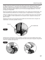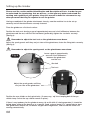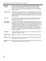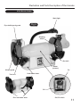
1
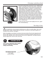
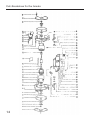
Code 505196 AT8G2 Heavy Duty Grinder Index of Contents Page No. Index of Contents 02 Declaration of Conformity 03 What’s in the Box 04 General Instruction for the 230V Machines 04-05 Specific Safety Precautions for Grinding Machine 06 Initial Assembly 07 Setting up the Grinder 08-09 Specification 09 Identification and Description of the Grinder 10 Illustration and Parts Description of the Grinder 11 Changing a Grinding Wheel 12-13 Dressing a Stone 13 Parts Breakdown for the Grinder 14 Parts List for the Grinder 15 Warning Fully read manual and safety instructions before use 02 Ear protection should be worn The symbols below advise that you follow the correct safety procedures when using this machine. Eye protection should be worn Dust mask should be worn HAZARD Motor gets hot Declaration of Conformity Copied from Z1A 05 01 55256 001 The undersigned, L. Geng authorised by Yancheng Baoding Electrical Tools Co., Ltd. No. 88 Yandu Road, Yandu New District 224005 Yanchang People’s Repubic of China declares that this product: Bench Grinder MD32205HD Machine type MD3225HD meets the specifications laid down in Council directive: EN 55014-1/A2:2002 55014-1/A1:2001 EN 61000-3-2:2002 EN 61000-3-3:A1:2001 EN 61029-2-4:2003 authorised by Yancheng Baoding Electrical Tools Co.Ltd. 03 What’s in the Box Model Number: 1 No: MD3220HD 8” Grinder Grinding machine with grinding wheels and lamp fitted 2 No. Spark Guards assembled complete Plastic Bag Containing, 2 No. M8 Star Bolts 2 No. M4 Raised Head Bolts complete with M4 Anti Vibration Washer M4 Washers M4 Nut 1 No. Guarantee Card 1 No. Instruction Manual General Instructions for 230V Machines Good Working Practices/Safety The following suggestions will enable you to observe good working practices, keep yourself and fellow workers safe and maintain your tools and equipment in good working order. ! WARNING!! KEEP TOOLS AND EQUIPMENT OUT OF THE REACH OF YOUNG CHILDREN Mains Powered Tools Primary Precautions These tools are supplied with a moulded 13 Amp. Plug and 3 core power cable. Before using the tool inspect the cable and the plug to make sure that neither are damaged. If any damage is visible have the tool inspected/repaired by a suitably qualified person. If it is necessary to replace the plug, it is preferable to use an ‘unbreakable’ type that will resist damage on site. Only use a 13 Amp plug, and make sure the cable clamp is tightened securely. Fuse as required. If extension leads are to be used, carry out the same safety checks on them, and ensure that they are correctly rated to safely supply the current that is required for your machine. 04 General Instructions for 230V Machines Work Place/Environment The machine is designed for indoor use, do not use when or where it is liable to get wet. If the tool is to be used outside and it starts to rain (unusual though this would be in U.K.), stop work and move it inside. If tool has got wet; dry it off as soon as possible, with a cloth or paper towel. Do not use 230Va.c. powered tools anywhere within a site area that is flooded or puddled, and do not trail extension cables across wet areas. Keep the tools clean; it will enable you to more easily see any damage that may have occurred. Clean the tool with a damp soapy cloth if needs be, do not use any solvents or cleaners, as these may cause damage to any plastic parts or to the electrical components. Keep the work area as uncluttered as is practical, this includes personnel as well as material. Under no circumstances should CHILDREN be allowed in work areas. It is good practice to leave the tool unplugged until work is about to commence, also make sure to unplug the tool when it is not in use, or unattended. Always disconnect by pulling on the plug body and not the cable. Once you are ready to commence work, remove any tools used in the setting operations (if any) and place safely out of the way. Re-connect the tool. Carry out a final check e.g. check the cutting tool, drill bit etc., is securely tightened in the tool, check you have the correct speed and function set, check that the power cable will not ‘snag’ etc. Make sure you are comfortable before you start work, balanced, not reaching etc. If the work you are carrying out is liable to generate flying grit, dust or chips, wear the appropriate safety clothing, goggles, gloves, masks etc. If the work operation appears to be excessively noisy, wear ear-defenders. If you wear your hair in a long style, wearing a cap, safety helmet, hairnet, even a sweatband, will minimise the possibility of your hair being caught up in the rotating parts of the tool, likewise, consideration should be given to the removal of rings and wristwatches, if these are liable to be a ‘snag’ hazard. Consideration should also be given to non-slip footwear, etc. If you are allowing another person to use the machine, ensure that they are suitably qualified to use it. Do not use any tools or machinery if you are under the influence of drink, drugs or prescribed medication. Do not work with cutting or boring tools of any description if you are tired, your attention is wandering or you are being subjected to distraction. A deep cut, a lost fingertip or worse is not worth it! Do not use this machine within the designated safety areas of flammable liquid stores or in areas where there may be volatile gases. There are very expensive, very specialised machines for working in these areas, THIS IS NOT ONE OF THEM. Check that cutters, drills etc., are the correct type and size, are undamaged and are kept clean and sharp, this will maintain their operating performance and lessen the loading on the machine. Above all, OBSERVE…. make sure you know what is happening around you, and USE YOUR COMMON SENSE. 05 Specific Safety Precautions for Grinding Machines 1. Do not operate your machine until it is completely assembled and installed according to the instructions. 2. If you are not familiar with the operation of grinding machines obtain advice from your supervisor or instructor or another qualified person. 3. Only use grinding wheels or attachments rated higher than 3600 rpm with a 5/8” (16mm) arbor on this machine. 4. Never use a chipped or cracked wheel. Always inspect each wheel before mounting it on the grinder. If during inspection you discover a damaged grinding wheel; replace it immediately. 5. Do not over tighten wheel nuts. 6. Always maintain a distance of 1.5mm or less between the wheel and the tool rest. Adjust the tool rests as the wheels decrease in size. 7. Ensure the tool rests are tightened so they cannot move while in use. 8. Never grind on a cold wheel. The grinder should always be run for at least one minute before applying work to it. 9. Never grind on the side of the wheel. Always grind on the face of the wheel only. 10. Never apply coolant directly to a grinding wheel, it may cause the bonding to fail. If the work piece becomes hot, dip it into a water pot to cool it down. 11. Hot sparks are a hazard! Never carry out grinding operations near flammable material of any type (ie solid, gas, liquid). 12. Always make sure the spark guards and eye shields are in place, that they are properly adjusted and secured. 13. Keep the sparks guards close to the wheels and re-adjust them as the wheels wear. 14. Ensure the soft washer and the flanges furnished with the grinder, are used to mount any attachments (grinding wheels, wire brushes, buffing wheels, etc) onto the shaft. 15. Always stand to one side of the grinder when starting the machine. 16. Avoid awkward hand positions where a sudden slip could cause the hands to come into contact with a grinding wheel, wire brush etc. 17. If the wheel requires dressing, dress only the front of the wheel, do not dress the sides. 18. Do not use any attachment that causes the machine to vibrate. If after changing grinding wheels or adding attachments, the machine does vibrate; remove the recently replaced item and change again. 19. Grinding creates heat. Do not touch the work face of the work piece until you are sure it has cooled down sufficiently. 06 Initial Assembly Carefully unpack the machine and all the loose items from the box. Check the contents against the “What’s in the box” list. If any items are missing please contact our technical services department using the telephone numbers that you will find in our catalogue. Having removed all the items from the box, please dispose of your unwanted packaging responsibly. A lot of the packaging is biodegradable. Remove the protective coating from all unpainted parts. This coating may be removed with a soft cloth moistened with paraffin (do not use acetone, petrol or lacquer thinners for this purpose). Initially we suggest that you merely carry out a ‘loose’ assembly of the various parts of the grinder. After assembly has been completed we will set up the various components correctly and tighten securely. Identify the Tool Rests and secure them to the inside faces of the wheel covers using the star handled bolts and washers provided. (See fig 1). Tool rest Star handled bolt Fig 1 Identify the Eye shield guards, these assemblies are universal and can be fitted to either side of the machine. Secure into the hard point the top of the stone cover part of the guard, using the M4 screws etc. provided. (See figs 2 & 3). Fig 2 07 Setting up the Grinder Please read the section entitled Identification and Description of Parts, in order for you to understand the terminology that we will use, so that you may better understand the working and capability of your grinder. Keep this manual to hand for reference for any other personnel that may be required to use the grinder. Having assembled all the grinder attachments loosely, now the machine has to be set up correctly and all the attachments securely fastened. Place the grinder on a flat level surface. Position the tool rests leaving a gap of approximately one and a half millimetres between the grindstone and the rest, with the rest horizontal (preferably) tighten the star bolts securely. (See fig 3) ! Remember to adjust the tool rest as the grindstones wear down. Adjust the spark guards until they are just clear of the grindstone; fasten the fixing bolts securely. (See fig 4) ! Remember to adjust the spark guards as the grindstones wear down. Fig 3 Leave a gap of approximately one and a half millimetres between the grindstone and the rest Star bolt Tool rest Adjust the spark guards until they are just clear of the grindstone Fig 4 Position the eye shields on their pivot bolts, (if necessary, ‘nip’ the clamping bolt of the eye shield clamp so that the eye shields remain in place). If there is any tendency for the grinder to move, tip or tilt while it is being operated, it should be bolted down; either to the bench or to a specific stand, or base board. It is a good idea to dress new grindstones before use, to remove any possible irregularities, and ensure the stones are running concentrically. 08 Setting up the Grinder Carry out a final check e.g. start the machine, check it runs smoothly. On each side, check that the spark guard is adjusted down to the stone, check the gap between the tool rest and the stone is correct, check the stone is not badly deformed (rounded edges, grooved face, etc; unless you have specifically shaped the stone to these profiles)check the eye shield is correctly positioned. Have a cooling pot to hand if you need it, and remember safety goggles are a good investment (you are only issued with 1 pair of eyes). Specification Code505196 ModelAT8G2 RatingTrade Power900W Voltage 230V Speed2,950rpm Wheel Diameter 200mm Wheel Width 32mm Bore31.75mm(1.1/4”) Dust Extraction Outlet 40mm Weight28kg 09 Identification and Description of the Grinder Grinding machine Essentially a double ended motor, with a mounting base, the motor flanges mount the wheel guards. The motor base contains the NVR switch and mounts the machine lamp. The base also has four 15mm holes cast into it to facilitate mounting the grinder to a stand or bolting it down to a bench. Wheel guards Two formed metal guards that enclose the grinding wheels. They are each formed in two parts. The inner part is mounted onto the motor flange, and the outer part is bolted to it. There are various ‘hard point locations’ with captive nuts fitted, that accept the fixing bolts that secure the attachments of the machine. Tool rests Formed castings that comprise the tool rest mounting arm and the tool rest proper. They are bolted into two hard points on the lower inside edges of the wheel guards. Eye shield/ spark guards Clear protective shields with an integrated magnifiying glass for close up inspection of work that mount over the grindstone to afford a view of the workpiece, but offer protection for the eyes, They are mounted onto the spark guards making a complete assembly that bolts through a hard point on the upper part of the stone cover. The spark guard itself has an elongated slot to allow positioning and adjustment as the wheel diameter decreases. Their function is to contain any material (esp. sparks) that would be tracked around the grindstone and sprayed out of the machine esp. over the hands. Work light Integral worklight, with flexible ‘move and stay’ column, energised with the application of the mains power. ON/OFF switch NVR switch, marked as standard with ‘I’ indicating ON and ‘O’ indicating OFF. Hold down holes Four holes that are formed in the base casting to enable the grinder to be bolted down to the bench or a stand. Dust extraction There are two 40mm dust extraction ducts integrated to the wheel guards Ducts for the purpose of attaching a dust extractor. 10 Illustration and Parts Description of the Grinder AT8G Bench Grinder Work light Fig 5 Eye sheild/spark guard Grinding wheel Star bolt Motor (unseen) Wheel guard Tool rest On Hold down holes Off Dust extracton ducts On/Off switch 11 Changing a grinding wheel Ensure that the grinder is disconnected from the mains supply. ! Undo the nuts and bolts that secure the outer shell of the wheel guard to the inner shell. Remove the outer shell and place it and the nuts, bolts and washers carefully aside. (See figs 6 & 7) Fig 6 Fig 7 Loosen the nut holding the grinding wheel to the shaft. Carefully remove the left handed nut, the plate flange and the soft washer that is clamping the grindstone in place. (See figs 8 & 9) Then, very carefully remove the grindstone from the shaft, take care that no damage or distortion is done to the bush (if one is fitted). (See fig 10) Now is a good time to clean out the interior of the wheel guard, removing any loose or compacted material that may have accumulated. Carefully inspect the new grinding wheel before it is fitted, check that there are no cracks, and there is no damage to either the front face or the edges. If required, fit the bush to the grindstone. Carefully mount the grindstone onto the shaft, reposition the soft washer and the wheel flange, replace the holding nut and tighten carefully. Do Not Overtighten. Refit the outside shell of the wheel guard and secure with its nuts and bolts. Refit the tool rest, positioning as in “Setting up the grinder”. Fasten securely. Plate flange Nut 12 Fig 8 Fig 9 Changing a grinding wheel Reset the spark guards and tool rest as for “setting up the grinder” instructions. Reconnect the grinder to the mains supply, give the grinder a ‘short burst’, by switching it on and off quickly. Check the grinder is not subject to any undue vibration. If the grinder does vibrate, strip it down again and check that the bush (if fitted) is correctly positioned and is the correct size for the stone and the spindle. Check the bore of the stone is correct. If these all seem correct refit and carryout the ‘quick burst’ procedure again. If the machine is still vibrating, discard the stone and replace with another one. Run up to speed normally. Leave the machine running for at least one minute before carrying out any work. Apply a workpiece and check that the spark guard is correctly positioned and that the tool rest is securely fixed. Fig 10 If necessary dress the new stone lightly to ensure a ‘good face’ and concentricity. Dressing a stone ! If the grindstones wear unevenly, producing crests, dips or rounded edges, they should be dressed out using a suitable wheel dressing tool. (A selection of stone dressing tools are available in the Axminster catalogue.) Switch the grinder on and allow it to run for at least one minute. Rest the dressing tool on the tool rest and advance it to the stone until it touches the maximum diameter; gently move the dresser back and forth across the face of the stone until all irregularities have been removed and the edges of the stone are nice and sharp. ! PLEASE NOTE This is not a procedure that can be rushed, it must be carried out slowly and steadily. Dressing the wheel using a Wheel Dressing Stick or Devil stone Part No. DEVILS 13 Parts Breakdown for the Grinder 14 Parts List for the Grinder 15 The Axminster guarantee is available on Hobby, Trade, Industrial, Engineer, Air Tool & Axcnc Technology Series machines It’s probably the most comprehensive FREE guarantee ever- buy with confidence from Axminster! So sure are we of the quality, we cover all parts and labour free of charge for three years! • Look for the icon and put your trust in Axminster • No registration necessary - just keep your proof of purchase • Optional Service Plan for Industrial Series machinery Great value & easy-to-use, perfect for use at home Solid, reliable machines designed for daily use Top performers with class leading features and build quality for use in busy workshops Quality, precision machines for the workshop or education Small machines for the home engineer Compressors and tools for home or workshop use, durable and great value Free Three Year Guarantee on Axminster Hobby, Trade and Industrial Series woodworking and engineering machines, Axminster Air compressors and Air Tools, and bench top grinders - no registration necessary just proof of purchase. We will repair or replace at our discretion and will collect only from a UK mainland address, irrespective of the original delivery address The Guarantee assumes that you have bought the correct machine for the required operation, in accordance with our guidelines; have operated and maintained it in accordance with the instruction manual; and that all cutting machines will be used with a blade which is sharp and serviceable at all times. It does not cover consumable items purchased with the original product, including original blades or abrasives Precision CNC machines for industry and education Normal wear and tear, misuse, abuse and neglect are excluded and the machine should not have been modified in any way. Please do not attempt to service the product without first contacting us; we are happy to guide you but failure to do so may invalidate the guarantee The Guarantee is transferable from owner to owner in the first three years but you must have original proof of purchase. Should we need to replace a machine in the first three years the guarantee will still continue to be effective from the original purchase date Full Terms and Conditions can be found here. This guarantee does not affect your statutory rights. For more information visit axminster.co.uk/3years Please dispose of packaging for the product in a responsible manner. It is suitable for recycling. Help to protect the environment, take the packaging to the local recycling centre and place into the appropriate recycling bin. Only for EU countries Do not dispose of electric tools together with household waste material. In observance of European Directive 2002/96/EC on waste electrical and electronic equipment and its implementation in accordance with national law, electric tools that have reached the end of their life must be collected separately and returned to an environmentally compatible recycling facility. Axminster Tool Centre, Unit 10 Weycroft Avenue, Axminster, Devon EX13 5PH axminster.co.uk