1
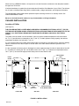
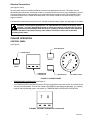
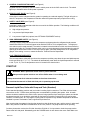
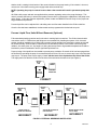
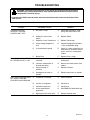
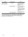
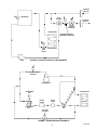
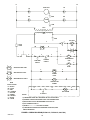
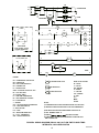
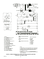
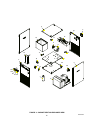
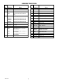
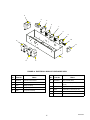
IMI CORNELIUS REMCOR INC g 500 REGENCY DRIVE g GLENDALE HEIGHTS, IL 60139--2268 Telephone (800) 551--4423 Facsimile (800) 519--4423 CHILLER (“CH” SERIES) Models: Operator’s Manual CH 1001-A CH 1501-A CH 1502-A CH 1503-A Part No. 620914301 July, 2000 Revision C Control Code A THIS DOCUMENT CONTAINS IMPORTANT INFORMATION This Manual must be read and understood before installing or operating this equipment IMI CORNELIUS INC; 1999--2000 PRINTED IN U.S.A TABLE OF CONTENTS Page GENERAL INFORMATION . . . . . . . . . . . . . . . . . . . . . . . . . . . . . . . . . . . . . . . . . . . . . . . . . . 1 INTRODUCTION . . . . . . . . . . . . . . . . . . . . . . . . . . . . . . . . . . . . . . . . . . . . . . . . . . . . . . UNPACKING AND INSPECTION . . . . . . . . . . . . . . . . . . . . . . . . . . . . . . . . . . . . . . . . DESIGN DATA . . . . . . . . . . . . . . . . . . . . . . . . . . . . . . . . . . . . . . . . . . . . . . . . . . . . . . . . DATA PLATE INFORMATION . . . . . . . . . . . . . . . . . . . . . . . . . . . . . . . . . . . . . . . . . . . CHILLER INSTALLATION . . . . . . . . . . . . . . . . . . . . . . . . . . . . . . . . . . . . . . . . . . . . . . . LOCATION OF CHILLER . . . . . . . . . . . . . . . . . . . . . . . . . . . . . . . . . . . . . . . . . . . . . . ELECTRICAL CONNECTIONS . . . . . . . . . . . . . . . . . . . . . . . . . . . . . . . . . . . . . . . . . CHILLER OPERATION . . . . . . . . . . . . . . . . . . . . . . . . . . . . . . . . . . . . . . . . . . . . . . . . . CONTROL PANEL . . . . . . . . . . . . . . . . . . . . . . . . . . . . . . . . . . . . . . . . . . . . . . . . . . . . 1 1 1 1 2 2 3 3 3 START UP . . . . . . . . . . . . . . . . . . . . . . . . . . . . . . . . . . . . . . . . . . . . . . . . . . . . . . . . . . . . PROCESS LIQUID FLOW, UNITS WITH PUMP AND TANK (STANDARD) . . . PROCESS LIQUID FLOW, UNITS WITHOUT RESERVOIR (OPTIONAL) . . . . TEMPERATURE CONTROLLER OPERATION . . . . . . . . . . . . . . . . . . . . . . . . . . . . OPTIONAL EQUIPMENT . . . . . . . . . . . . . . . . . . . . . . . . . . . . . . . . . . . . . . . . . . . . . . . CHILLER MAINTENANCE . . . . . . . . . . . . . . . . . . . . . . . . . . . . . . . . . . . . . . . . . . . . . . CONDENSER . . . . . . . . . . . . . . . . . . . . . . . . . . . . . . . . . . . . . . . . . . . . . . . . . . . . . . . . FAN MOTOR . . . . . . . . . . . . . . . . . . . . . . . . . . . . . . . . . . . . . . . . . . . . . . . . . . . . . . . . . PUMP MOTOR . . . . . . . . . . . . . . . . . . . . . . . . . . . . . . . . . . . . . . . . . . . . . . . . . . . . . . . CIRCULATION SYSTEM . . . . . . . . . . . . . . . . . . . . . . . . . . . . . . . . . . . . . . . . . . . . . . FILTERS/STRAINERS . . . . . . . . . . . . . . . . . . . . . . . . . . . . . . . . . . . . . . . . . . . . . . . . 4 4 5 6 6 6 7 7 7 7 7 TROUBLESHOOTING . . . . . . . . . . . . . . . . . . . . . . . . . . . . . . . . . . . . . . . . . . . . . . . . . . . . . . 9 CHILLER DOES NOT OPERATE, CONTROL POWER LIGHT “OFF” . . . . . . . . . PUMP DOES NOT OPERATE, BUT POWER LIGHT IS “ON”. . . . . . . . . . . . . . . . UNIT RUNS CONTINUOUSLY, BUT IS NOT COOLING PROCESS LIQUID ENOUGH. . . . . . . . . . . . . . . . . . . . . . . . . . . . . . . . . . . . . . . . . . . . . . . . . . . . . . . . . . . . . CHILLER DOES NOT OPERATE, BUT POWER LIGHT IS “ON” AND RED SAFETY LIGHT IS “ON”. . . . . . . . . . . . . . . . . . . . . . . . . . . . . . . . . . . . . . . . . . . . . . . . WARRANTY . . . . . . . . . . . . . . . . . . . . . . . . . . . . . . . . . . . . . . . . . . . . . . . . . . . . . . . . . . . . . . 9 9 9 10 18 LIST OF FIGURES FIGURE 1. SAMPLE DATA PLATE . . . . . . . . . . . . . . . . . . . . . . . . . . . . . . . . . . . . . . . FIGURE 2. INSTALLATION . . . . . . . . . . . . . . . . . . . . . . . . . . . . . . . . . . . . . . . . . . . . . FIGURE 3. CONTROL PANEL . . . . . . . . . . . . . . . . . . . . . . . . . . . . . . . . . . . . . . . . . . . FIGURE 4. CH SERIES TEMPERATURE CONTROLLER . . . . . . . . . . . . . . . . . . . FIGURE 5. EXTERNAL RESERVOIR WATER LEVEL . . . . . . . . . . . . . . . . . . . . . . FIGURE 6. PROCESS LIQUID FLOW SCHEMATIC . . . . . . . . . . . . . . . . . . . . . . . . FIGURE 7. REFRIGERATION SCHEMATIC . . . . . . . . . . . . . . . . . . . . . . . . . . . . . . . FIGURE 8. WIRING DIAGRAM (CH 1001-A, 1501-A, 230/1/60) . . . . . . . . . . . . . . FIGURE 9. WIRING DIAGRAM (CH 1001 230/1/60 FLOW SWITCH HIGH TEMP. INTERLOCK, LOW LEVEL SWITCH) . . . . . . . . . . . . . . . . . . . . . . . . . . . . . . . . . . . . . FIGURE 10. WIRING DIAGRAM (CH 1501 230/3/60, 460/3/60 FLOW SWITCH HIGH TEMP INTERLOCK, LOW LEVEL ALARM) . . . . . . . . . . . FIGURE 11. CABINET SECTION EXPLODED VIEW . . . . . . . . . . . . . . . . . . . . . . . FIGURE 12. ELECTRICAL BOX ASS’Y EXPLODED VIEW . . . . . . . . . . . . . . . . . . 1 2 3 3 5 11 11 12 13 14 15 17 LIST OF TABLES TABLE 1. DESIGN DATA . . . . . . . . . . . . . . . . . . . . . . . . . . . . . . . . . . . . . . . . . . . . . . . i 1 620914301 GENERAL INFORMATION INTRODUCTION The REMCOR ”CH” Series Recirculating Liquid Chiller is designed to provide an accurate, reliable, and user-friendly system for cooling a continuous flow of pure liquid and keep that liquid at a constant temperature in various closed loop or tank cooling applications. The ”CH” Series Chiller consists of an air--cooled refrigeration system housed in a sturdy sheet metal frame and cabinet. A standard pump and insulated liquid reservoir package provides a complete liquid cooling and circulating system. The ”CH” Series Chiller is designed to operate in a clean laboratory or industrial environment where ambient temperatures range from 40 to100q F (5 to 38q C). With proper installation, operation, and maintenance, the ”CH” Series Chiller will provide years of trouble free service. UNPACKING AND INSPECTION This unit was thoroughly inspected before leaving the factory and the carrier has accepted and signed for it. Any damage or irregularities should be noted at the time of delivery and immediately reported to the carrier. Request a written inspection report from the Claims Inspector to substantiate any necessary claims. In the event that an immediate replacement is necessary, please contact REMCOR Chiller Sales at 1--800--551--4423. DESIGN DATA Table 1. Design Data CH1001--A CH1501--A CH1502--A CH1503--A 18,000 (5,272) 18,000 (5,272) 18,000 (5,272) 1 (.746 kW) 1 1/2 (1.12 kW) 1 1/2 (1.12 kW) 1 1/2 (1.12 kW) 230/1/60 11.0 Amps 230/1/60 13.0 Amps 230/3/60 16.4 Amps 460/3/60 10.0 Amps R134a R22 R22 R22 Cooling Capacity: 12,000 (3,515) BTU/hr (W) at 80_ F(27_ C) and 70_ F (21_ C) Liquid Temperature. Compressor Horsepower Electrical Data: Voltage/Phase/Hertz/Amperage Refrigerant Type: Reservoir Capacity 6.0 gallons (22.7 6.0 gallons (22.7 6.0 gallons (22.7 6.0 gallons (22.7 liters) liters) liters) liters) Physical Dimensions, Width ¢ Depth 22I¢ 26.5XI¢ 22I¢ 26.5XI¢ 22I¢ 26.5XI¢ 22I¢ 26.5XI¢ ¢ Height: 38.25I 38.25I 38.25I 38.25I (56cm ¢ 67cm (56cm ¢ 67cm (56cm ¢ 67cm (56cm ¢ 67cm ¢ 97cm) ¢ 97cm) ¢ 97cm) ¢ 97cm) Fittings: Process Connections 3/4” FPT (S/S) 3/4I FPT (S/S) 3/4I FPT (S/S) 3/4I FPT (S/S) Optimum Process Liquid Flow GPM 2.4 (9.0) 3.6 (13.6) 3.6 (13.6) 3.6 (13.6 (Liters/Min) Condenser Air Flow (CFM) 712 1050 1050 1050 DATA PLATE INFORMATION REMCOR PRODUCTS COMPANY GLENDALE HEIGHTS, IL. 60139--2268 MADE IN U.S.A. PART NO. VOLTS MODEL NO. HZ PH SERIAL NO. AMPS R134A BAR CODE FIGURE 1. SAMPLE DATA PLATE 1 620914301 When servicing a REMCOR Chiller, it is important to note the information contained on the data plate located in the upper rear of the Unit. If technical assistance is needed, the phone technician will need the Serial Number of your Chiller. That information is found on the Data Plate along with the model number, voltage requirement, and refrigerant information. The serial Number is also needed when replacement parts are being ordered or for warranty claims. See CHILLER WARRANTY PAGE. Be sure to include the serial number on any documentation or billing information. CHILLER INSTALLATION Location of Chiller (see Figure 2) THE CHILLER MUST BE LOCATED NEAR A PROPERLY GROUNDED ELECTRICAL OUTLET. THE CIRCUIT SHOULD BE FUSED AND NO OTHER ELECTRICAL APPLIANCE SHOULD BE CONNECTED TO THE CIRCUIT. ALL ELECTRICAL WIRING MUST CONFORM TO NATIONAL AND LOCAL ELECTRICAL CODES. The Chiller must be located in a well ventilated, indoor area where ambient temperatures will remain above 40_ F (5_ C) and will never increase above 100_ F (38_ C). To obtain optimum cooling capacity, the ambient temperature should be at or below 80_ F (27_ C). It is very important that the air intake and discharge sides of the chiller are not obstructed by other free standing objects. A minimum of two feet of space on all four sides of the chiller will be sufficient to prevent air flow obstructions. It is also important to direct any hot air discharge from other equipment away from the air intake side of the chiller. Condenser air entering the “CH” unit should be below 100_ F (38_ C) .Condenser air temperatures above 100_ F (38_ C) can cause the high pressure safety control to shut down the unit. PRESS GAUGE FILL PORT JUNCTION BOX INLET OUTLET 26-- 13/16 CONTROL PANEL 37-- 11/16 37-- 5/16 30-- 1/2 19-- 7/16 21-- 15/16 FRONT VIEW RESERVOIR LEVEL INDICATOR DRAIN VALVE AND PLUG (BEHIND PANEL) SIDE VIEW FIGURE 2. INSTALLATION 620914301 2 REAR VIEW Electrical Connections (see Figure 2 and 8) All wiring must conform to the National Electric Code and any applicable local codes. The Chiller must be permanently wired by means of electrical conduit to a properly fused disconnect of proper amperage or wired to a properly rated power cord and plugged into an outlet with the appropriate disconnect and amperage rating. The electrical junction box, located on the back panel of the Chiller, includes a four terminal strip for power supply connection. The data plate, located next to the junction box, includes the actual voltage, phase, and amperage of the Chiller. CAUTION: On three-phase applications, it is important that the rotation of the pump, when supplied , is correct. Operating the pump in reverse for more than a few seconds will result in permanent pump damage. When the pump is operating, the shaft rotation must match the direction indicated on the pump housing. If the rotation is incorrect, reverse two of the three incoming power leads. CHILLER OPERATION CONTROL PANEL (see Figure 3) BLUE INDICATOR POWER SWITCH BYPASS CONTROL POWER SAFETY TEMPERATURE CONTROLLER RED INDICATOR PRESS GAUGE FIGURE 3. CONTROL PANEL 1. TEMPERATURE CONTROLLER (see Figure 4) The TEMPERATURE CONTROLLER uses a PID control algorithm to precisely monitor and control the process set point temperature. The Unit has a large LED READOUT that displays temperature. For adjusting set point and programming options, see section on TEMPERATURE CONTROLLER OPERATION. 7 0 FIGURE 4. CH SERIES TEMPERATURE CONTROLLER 3 620914301 2. CONTROL POWER SWITCH/LIGHT (see Figure 3) A lighted ON/OFF push button switch is used to switch power to the 24 VAC control circuit. The switch lights up to indicate that the Chiller power is present. 3. BYPASS LIGHT (BLUE) (see Figure 3) A blue light is used to indicate when the system is operating at a reduced capacity. The light will cycle on and off in response to the Temperature Controller when the system temporarily requires less cooling. 4. SAFETY LIGHT (RED) (see Figure 3) A red light is used to indicate that a fault has occurred in the Chiller operation. The following conditions will illuminate the safety light. A. High refrigerant pressure. B. Low process liquid temperature. C. Low process Liquid flow (optional, see OPTIONAL EQUIPMENT section). 5. HIGH--PRESSURE SAFETY (see Figure 3) The high-pressure safety will shut down the compressor and pump when the refrigerant head pressure reaches 240-PSIG for R--134A refrigerant units and 350--PSIG for R--22 refrigerant units. The high pressure switch must be reset manually. The switch is located in the electrical box which must be accessed by removing the Chiller lid. The high-pressure switch can be re-set by depressing the reset button through the opening in the electrical box cover. If the control opens again, check the setting with a set of refrigeration gauges. If the setting is correct, contact the Remcor Technical Service Department. LOW--TEMPERATURE SAFETY The low--temperature safety will shut down the compressor and the pump when the process liquid temperature drops below 35_ F (1.7_ C). The switch will automatically reset when the liquid temperature is restored to 38_ F (3.3_ C). The low temperature control is located in the electrical box. START UP WARNING: Never operate the Chiller with it’s panels removed. Always use the power switch to turn off the Chiller when it is not being used. Always ensure that all air inlets and outlets are free from obstruction. Be sure that the reservoir is filled with fluid prior to powering up the unit. Process Liquid Flow, Units with Pump and Tank (Standard) Follow standard plumbing practices and local codes in making liquid connections. The Chiller inlet and outlet connections are 3/4”. Flexible hose and fittings are recommended for plumbing the system. A No. 20 mesh strainer should be installed on the Chiller inlet to prevent foreign particles from entering the system and should be cleaned monthly. Lines should be routed with as few bends as possible. Prevent lines from running near radiators, hot water pipes, etc. Any lengths of tubing that are exposed to high ambient temperatures should be insulated to prevent condensation and/or significant liquid heat loss. After ensuring that the system is free from the obstruction, that all valves are open, and the reservoir when available is full, push the CONTROL POWER switch to the “ON” position. The pump should now be operating. On three--phase units such as the CH1502--A and the CH1503--A, it is important to check the pump rotation. Remove the left--side panel. Momentarily push the POWER button in and observe the motor shaft. Make sure 620914301 4 that the shaft is rotating in the direction of the arrow indicated on the pump housing. If the rotation is incorrect, reverse two of the three incoming power supply leads at the terminal strip. NOTE: Operating the pump in reverse for more than a few seconds will result in permanent pump damage. All Chillers with pumps and tank are supplied with a pressure regulating valve on the pump discharge. This valve is preset at the factory to ensure that system pressure does not exceed the capabilities of the pump motor and/or piping. If this valve requires adjustment, please contact the REMCOR Service Group for the proper setting procedure and pressures. Process liquid flow can be adjusted VIA a throttling valve and flow meter installed in the Chiller outlet line. Once the flow has been established, the thermostat can be programmed to the desired set--point. Process Liquid Flow, Units Without Reservoir (Optional) Follow standard plumbing practices and local codes in making liquid connections. The Chiller inlet and outlet connections are 3/4”. Flexible hose and fittings are recommended for plumbing the system. A No. 20 mesh strainer should be installed on the Chiller inlet to prevent foreign particles from entering the system and should be cleaned monthly. Lines should be routed with as few bends as possible. Prevent lines from running near radiators, hot water pipes, etc. Any lengths of tubing that are exposed to high ambient temperatures should be insulated to prevent condensation and/or significant liquid heat loss. Proper priming of the liquid lines is essential to prevent pump cavitation. Be certain all air has been purged from the lines before operating the pump for an extended period of time. Be sure to remove any loops in the lines that may trap air. The pump must have a supply of water with the level of the liquid above the inlet of the Chiller. The supply tank must feed the Chiller from the side of the tank below the water level (see Figure 5). CHILLER INLET LINE WATER LEVEL EXTERNAL RESERVOIR CHILLER W/O TANK CORRECT CHILLER INLET LINE CHILLER INLET LINE WATER LEVEL CHILLER W/O TANK WATER LEVEL EXTERNAL RESERVOIR CHILLER W/O TANK CHILLER INLET LINE CHILLER W/O TANK WATER LEVEL EXTERNAL RESERVOIR EXTERNAL RESERVOIR WATER LEVEL IS BELOW CHILLER INLET INCORRECT AIR CAN BE TRAPPED IN CHILLER INLET INCORRECT WATER FEEDING FROM TOP OF TANK INCORRECT FIGURE 5. EXTERNAL RESERVOIR WATER LEVEL 5 620914301 TEMPERATURE CONTROLLER OPERATION (see Figure 4) During normal operation, the process temperature will be displayed on the Controller. The following procedure should be followed to adjust the Controller set point: 1. Push and hold the “ *” button located at the bottom left corner of the Controller. The set point will be displayed. 2. While holding the “ *” button, press the desired value is displayed. (“ UP” ) or “ DOWN” button to raise or lower the set point until 3. Release the “ *” button. The display will again show the system liquid temperature. The set point can be viewed at any time by pressing the “ *” button. The Controller set point range has been preset at the factory. The range is 40_ F (5_ C) to 100_ F (38_ C). If operation outside this range is required, contact the Remcor Technical Services Department. OPTIONAL EQUIPMENT LX Model--Is equipped with a low--level alarm and a high--temperature interlock as optional items. EX Model--Is equipped with a low--level alarm, high--temperature interlock, low--flow interlock, and RS232 communications as optional items. A detailed description of these options is as follows: Low--Level Alarm--A float switch located in the liquid reservoir will activate an audible alarm when the tank level drops below a critical level. It is important to note that this alarm will not shut down the system. The alarm will sound until the unit reservoir has been refilled to the full line on the sight glass. High--Temperature Interlock--A second output on the temperature controller will sense the process liquid temperature and energize a set of normally open terminals located inside the electrical junction box on the back of the Chiller when the temperature exceeds a set limit above the set point. The high--temperature interlock is preset at the Factory to activate at 25_ F (13.9_ C) above the process set point with a hysteresis of 3.6_ F (2.0_ C). If other values are required, please contact the Remcor Technical Services Department. Low--Flow Interlock--A flow switch located in the Chiller water plumbing will sense when the process liquid flow has dropped below 0.5 gpm. The flow switch will energize a set of normally open terminals located in the electrical junction box on back of the Chiller. The low flow condition will also shut down the compressor and pump coils of the Chiller and illuminate the red fault indicator on the control panel. The Chiller will remain shut down and the terminals open until full flow is restored to the Chiller. NOTE: The interlock terminals should be connected to a load that is appropriate for the following: 1. High--Temperature Interlock uses a solid--state relay rated at 5 FLA, 30 LRA @ 240 VAC. 2. Low--Flow Interlock uses a mechanical relay rated at 6 FLA, 1/2 H.P. @ 277 VAC. RS 232 Communications--Allows the Controller to be connected to a personal computer to monitor and/or program the Controller from a remote location up to 50 feet (15 meters). CHILLER MAINTENANCE WARNING: Disconnect electrical power to the Chiller to prevent personal injury before attempting any internal maintenance. Only qualified personnel should service the internal components or electrical wiring. 620914301 6 Condenser On air--cooled Chillers, the CONDENSER FINS should be cleaned by blowing compressed air through the condenser from the fan side. Dirt and debris accumulate on the condenser fins over time, and this build up can severely reduce the performance of the Chiller. Cleaning of the CONDENSER COIL FINS should be done approximately every three months, depending upon cleanliness of your application. Fan Motor On air--cooled Chillers, the condenser FAN MOTOR should be lubricated every 6 months with a few drops of SAE 10 oil. Pump Motor The PUMP MOTOR should be lubricated with thirty drops of SAE 20 oil once a year. Circulation System The CIRCULATION SYSTEM should be drained and flushed periodically to avoid build up and a possible flow restriction caused by contaminants. Filters/Strainers The STRAINER at the Chiller inlet should be removed and cleaned monthly. The “Y” STRAINER, located inside the unit at the inlet of the pump, should be cleaned periodically depending on applications. If a reduction in flow or cavitation of the pump occurs, remove the strainer, flush it out with water, then replace. 7 620914301 THIS PAGE LEFT BLANK INTENTIONALLY 620914301 8 TROUBLESHOOTING WARNING: Disconnect electrical power to the Chiller to prevent personal injury before attempting any internal maintenance. Only qualified personnel should service internal components or electrical wiring. If repairs to the Chiller must be made, disconnect electrical power to the unit, then shut off the water source. TROUBLE CHILLER DOES NOT OPERATE, CONTROL POWER LIGHT “OFF” PUMP DOES NOT OPERATE, BUT POWER LIGHT IS “ON”. UNIT RUNS CONTINUOUSLY, BUT IS NOT COOLING PROCESS LIQUID ENOUGH. PROBABLE CAUSE REMEDY A. No Power To Unit. A. Check Main disconnect fuses, wiring, and power lead to unit. B. Defective Control Power Switch. B. Replace Switch C. Defective Control Transformer. C. Replace Transformer D. Wrong Voltage Supplied to Unit. D. Supplied Voltage Must be within r 10% of nameplate rating. E. 3--Phase Monitor tripped. E. Check for correct voltage level on each phase of incoming 3--phase power. Check for correct phase rotation. F. Blown Fuse. F. Replace Fuse (1 Amp). A. Line to or from Chiller is restricted. A. Inspect lines and remove any obstructions. B. Internal or external filter is blocked with debris. B. Remove and clean strainer, then replace. C. Pump Contactor is defective. C. Replace Contactor. D. Damaged pump motor or impeller. D. Replace pump motor or impeller. A. Condenser is restricted. A. Clean condenser. B. Unit low on refrigerant. B. Call Service. C. Inefficient compressor. C. Call Service. D. Unit is undersized for application. D. Call REMCOR Chiller Sales Rep. E. Bypass gas valve stuck open. E. Replace solenoid valve. 9 620914301 TROUBLE CHILLER DOES NOT OPERATE, BUT POWER LIGHT IS “ON” AND RED SAFETY LIGHT IS “ON”. PROBABLE CAUSE REMEDY A. Unit is operating under high pressure conditions. A. Check for dirty condenser fins or obstruction of chiller air intake. Press high pressure manual reset switch. If this problem persist, contact Remcor Service Department. B. Unit is operating under low temperature conditions. B. Low or no process liquid flow. Ensure that there is adequate flow through system plumbing. or Process liquid is too cold, below 35_ F. Increase thermostat setting or bypass valve stuck open. Replace solenoid valve. Check for proper voltage. or Defective thermostat, replace. C. Unit has experienced low flow condition (LX and EX units). C. Check for obstruction in process liquid line plumbing. NOTE: When servicing a REMCOR Chiller, it is important to note all information provided on the DATA PLATE located in the upper rear of the unit. If technical assistance is needed, the REMCOR Service Technician will need this information along with any description of the problem(s) you are encountering. The serial number and other information will also be required when ordering replacement parts and any other Warranty Claims. 620914301 10 PROCESS RETURN RESERVOIR AUTO BYPASS T F PROCESS SUPPLY FLOW SWITCH (OPTIONAL) EVAPORATOR PROCESS CONTROL TEMPERATURE SENSOR T LOW TEMP SAFETY PUMP FIGURE 6. PROCESS LIQUID FLOW SCHEMATIC P HIGH PRESSURE CONTROL COMPRESSOR CONDENSER FAN EVAPORATOR SIGHT GLASS FILTER/ DRYER CONDENSER COIL TXV HOT GAS SOLENOID F FIGURE 7. REFRIGERATION SCHEMATIC 11 620914301 L1 L2 COND UNIT M1 M1 GRN M2 M2 PUMP GRN 230V 24V GRN HOT GAS 6 Y FUSE 1 AMP OR SOL B R 7 R 5 1 R 2 OR Y 3 Y COMPRESSOR COIL - RED INICATOR LIGHT W - WHITE INICATOR LIGHT W 6 W POWER LIGHT 2 OR 6 W T CONTROLLER POWER WIRE COLOR CODING B = BLACK BL = BLUE R = RED OR = ORANGE Y = YELLOW G = GREEN BR = BROWN V = VIOLET W = WHITE 8 2 R B LL SWITCH A AUD ALARM NOTES: 1) CONDENSER FAN IS ONLY REQUIRED ON AIR COOLED UNITS. 2) THERMAL OVERLOADS ARE BUILT INTO THE COMPRESSORS. 3) SEE INSTRUCTION ON TRANSFORMER FOR HOOK UP. 4) LAST TERMINAL USED: 15 5) ITEMS IN BOX ARE OPTIONAL. 6) COMPONENTS SHOWN IN DE-- ENERGIZED CONDITION, WITH EMPTY RESERVOIR. FIGURE 8. WIRING DIAGRAM (CH1001--A, CH1501--A, 230/1/60) 620914301 6 W PUMP - BLUE INICATOR LIGHT R 6 W M2 2 OR 12 W M1 V HI PRESS SAFETY LOW TEMP SAFETY BL 5 V 4 V 6 BL 6 W M1 R L1 L2 COMPRESSOR B M2 230V PUMP TRANSFMR 24V SVHG CT Y 5 VDC + - FU1 1 R 15 14 7 R FL PB 2 OR BL 5 R V M1 SSR M2 R R 12 FS 13 SSR RATING 5 FLA, 30 LRA @ 240V HI-TEMP INTERLOCK LT 9 R R 3 Y HP J 4 V M3 11 10 BL BL W 6 W 6 W 6 TR 2 W 2 OR 6 W 2 OR M3 6 W 6 5 V R LOW FLOW RELAY 1/3 H.P., 240V. 10A. 6 W 6 CAL B LOW FLOW INTERLOCK W SSR W 2 R LLS PUMP 8 R 6 A W LEGEND M1 - COMPRESSOR CONTACTOR M2 - PUMP RELAY M3 - LOW FLOW INTERLOCK PB - PUSHBUTTON FL - FAILURE LIGHT SVHG - SOLENOID VALVE HOT GAS BL - HOT GAS LIGHT TR - BYPASS TIMER LT - LOW TEMP THERMOSTAT BL BLUE INDICATOR LIGHT R RED INDICATOR LIGHT W WHITE INDICATOR LIGHT HP - HIGH PRESSURE CONTROL FS - FLOW SWITCH J - JUMPER CAL - CAL ELECTRONIC THERMOSTAT LLS - LOW LEVEL SWITCH A - AUDIO ALARM FU1 - FUSE HTI - HIGH TEMP INTERLOCK CT - CAL C. THERMOSTAT SSR - SOLID STATE RELAY NOTES: WIRE COLOR CODING W = WHITE V = VIOLET BR = BROWN G = GREEN Y = YELLOW OR = ORANGE R = RED BL = BLUE B= BLACK 1) CONDENSER FAN IS ONLY REQUIRED ON AIR COOLED UNITS. 2) THERMAL OVERLOADS ARE BUILT INTO THE COMPRESSOR. 3) SEE INSTRUCTIONS ON TRANSFORMER FOR HOOK-- UP. 4) LAST TERMINAL USED: 15 5) ITEMS IN BOX ARE OPTIONAL. 6) COMPONENTS SHOWN IN DE-- ENERGIZED CONDITION WITH EMPTY RESERVOIR. FIGURE 9. WIRING DIAGRAM (CH1001 230/1/60 FLOW SWITCH HIGH TEMP. INTERLOCK, LOW LEVEL SWITCH 13 620914301 L1 L2 L3 M1 BL R G COMPRESSOR B CCH 230V 460V M2 PUMP TRANSFMR 24V + 5 V DC 15 14 PB FUI SSR 12 7 FL 1 2 R OR 5 R V 10 11 M3 BL LOW FLOW INTERLOCK LT 9 R R M1 3 HP Y LP 4 M3 V 5 V 2 W CAL OR 6 W 6 W 2 6 W W R OR 6 W 6 TR 2 LOW FLOW RELAY 1/3 HP @ 230V 10A W M2 FS 6 6 BL R 13 SSR RATING = 5 FLA, 30 LRA @240V HI TEMP INTERLOCK BL SVHG CT Y _ 6 B SSR W W 2 LLS 8 R LEGEND M1 - COMPRESSOR CONTACTOR M2 - PUMP RELAY M3 - LOW FLOW INTERLOCK PB - PUSHBUTTON FL - FAILURE LIGHT SVHG - SOLENOID VALVE HOT GAS BL - HOT GAS LIGHT TR - BYPASS TIMER LT - LOW TEMP THERMOSTAT HP - HIGH PRESSURE CONTROL FS - FLOW SWITCH CAL - CAL ELECTRONIC THERMOSTAT LLS - LOW LEVEL SWITCH A - AUDIO ALARM FUI - FUSE LAMP HTI - HIGH TEMP INTERLOCK CT - CAL C THERMOSTAT SSR - SOLID STATE RELAY CCH-- CRANK CASE HEATER R BL A BLUE INDICATOR LIGHT WIRE COLOR CODING R RED INDICATOR LIGHT W WHITE INDICATOR LIGHT B = BLACK BL = BLUE R = RED OR = ORANGE Y = YELLOW G = GREEN BR = BROWN V = VIOLET W = WHITE NOTES: 1. CONDENSER FAN IS ONLY REQUIRED ON AIR COOLED UNITS 2. THERMAL OVERLOADS ARE BUILT INTO THE COMPRESSOR 3. SEE INSTRUCTIONS ON TRANSFORMER FOR HOOK-- UP 4. LAST TERMINAL USED: 15 5. ITEMS IN - - - - - - - - - - - - - - - - - - - - BOX ARE OPTIONAL 6. COMPONENTS SHOWN IN DE-- ENERGIZED CONDITION WITH EMPTY RESERVOIR FIGURE 10. WIRING DIAGRAM CH1501 230/3/60, 460/3/60 FLOW SWITCH HIGH TEMP. INTERLOCK, LOW LEVEL ALARM 620914301 6 W 14 6 21 16 3 10 17 8 9 15 23 11 13 1 2 5 26 12 22 14 18 19 25 24 20 7 4 FIGURE 11. CABINET SECTION EXPLODED VIEW 15 620914301 CABINET SECTION Item No. Part No. Item No. Name Part No. Name 1 620028005 Base, Pump/Tank 10 620306708 Electrical Box Ass’y 2 620028001 Panel, Front 11 41331 Y-Strainer 3 31036 Electrical Junction Box (DX Unit) 12 61003 TXV (Model CH1001--A) 15696 Electrical Junction Box (EX AND LX Units) 13 60686 Filter Dryer 14 60687 Sight Glass 620604501 Condensing Unit (Model CH1001--A) 15 620602503 Evaporator Ass’y (Model CH1001--A) 620604403 Condensing Unit (Model CH1501--A) 16 620603201 Foamed Reservoir 620604402 Condensing Unit (Model CH1502--A) 17 22870 Fill Port (3/4-In. SS Coupling) 620604401 Condensing Unit (Model CH1503--A) 18 32806 Switch, Power 5 620028003 Panel, Side 19 620602701 Controller, Temperature 6 620028004 Lid, Chiller 20 620701209 Gauge, Pressure 7 620604302 Accumulator 21 620028002 Panel, Rear 8 32357 Pump (Model CH1001--A, CH1501--A and CH1502--A) 22 620602703 620602704 Solenoid Valve, Hot Gas Solenoid Coil, Hot Gas 32385 Clamp (Model CH1001--A, CH1501--A and CH1502A) 23 40646 Bypass Valve, Water 32382 Motor (Model CH1001--A, CH1501--A and CH1502--A) 24 32807 Indicator, Red 25 620311607 Indicator, Blue 33311 Motor, Pump (Model CH1503--A) 26 620028007 Base, Refrigeration 4 9 620914301 16 2 3 4 5 7 5 9 10 8 11 1 8 6 FIGURE 12. ELECTRICAL BOX ASS’Y EXPLODED VIEW Item No. Part No. Item No. Name Part No. Name 1 620028012 Enclosure, Electrical Box 6 620305802 Relay, Overload (460V) 2 32829R Transformer 7 620307501 3 31001 Safety, Low Temp Solid State Relay, High Temperature (LX, EX) 4 60501 Safety, High Pressure 8 620305902 Compressor/Pump (460V) Contactor 5 33082 Pump/Low Flow Relay 9 33339 Audible Alarm, Low Level (LX, EX) 10 31407 Fuse Block 11 620313801 Bypass Timer 17 620914301 WARRANTY IMI Cornelius Inc. warrants that all equipment and parts are free from defects in material and workmanship under normal use and service. For a copy of the warranty applicable to your Cornelius, Remcor or Wilshire product, in your country, please write, fax or telephone the IMI Cornelius office nearest you. Please provide the equipment model number, serial number and the date of purchase. IMI Cornelius Offices AUSTRALIA D P.O. 210, D RIVERWOOD, D NSW 2210, AUSTRALIA D (61) 2 533 3122 D FAX (61) 2 534 2166 AUSTRIA D AM LANGEN FELDE 32 D A-1222 D VIENNA, AUSTRIA D (43) 1 233 520 D FAX (43) 1-2335-2930 BELGIUM D BOSKAPELLEI 122 D B-2930 BRAASCHAAT, BELGIUM D (32) 3 664 0552 D FAX (32) 3 665 2307 BRAZIL D RUA ITAOCARA 97 D TOMAS COELHO D RIO DE JANEIRO, BRAZIL D (55) 21 591 7150 D FAX (55) 21 593 1829 ENGLAND D TYTHING ROAD ALCESTER D WARWICKSHIRE, B49 6 EU, ENGLAND D (44) 789 763 101 D FAX (44) 789 763 644 FRANCE D 71 ROUTE DE ST. DENIS D F-95170 DEUIL LA BARRE D PARIS, FRANCE D (33) 1 34 28 6200 D FAX (33) 1 34 28 6201 GERMANY D CARL LEVERKUS STRASSE 15 D D-4018 LANGENFELD, GERMANY D (49) 2173 7930 D FAX (49) 2173 77 438 GREECE D 488 MESSOGION AVENUE D AGIA PARASKEVI D 153 42 D ATHENS, GREECE D (30) 1 600 1073 D FAX (30) 1 601 2491 HONG KONG D 1104 TAIKOTSUI CENTRE D 11-15 KOK CHEUNG ST D TAIKOKTSUE, HONG KONG D (852) 789 9882 D FAX (852) 391 6222 ITALY D VIA PELLIZZARI 11 D 1-20059 D VIMARCATE, ITALY D (39) 39 608 0817 D FAX (39) 39 608 0814 NEW ZEALAND D 20 LANSFORD CRES. D P.O. BOX 19-044 AVONDALE D AUCKLAND 7, NEW ZEALAND D (64) 9 8200 357 D FAX (64) 9 8200 361 SINGAPORE D 16 TUAS STREET D SINGAPORE 2263 D (65) 862 5542 D FAX (65) 862 5604 SPAIN D POLIGONO INDUSTRAIL D RIERA DEL FONOLLAR D E-08830 SANT BOI DE LLOBREGAT D BARCELONA, SPAIN D (34) 3 640 2839 D FAX (34) 3 654 3379 USA D ONE CORNELIUS PLACE D ANOKA, MINNESOTA D (612) 421-6120 D FAX (612) 422-3255 LD004 4/21/98 620914301 18 THIS PAGE LEFT BLANK INTENTIONALLY 17 620914301 IMI CORNELIUS INC. CORPORATE HEADQUARTERS: One Cornelius Place Anoka, Minnesota 55303-6234 (763) 421-6120 (800) 238-3600


![Service Manual VA13 Carbonator [ 002818 ]](http://vs1.manualzilla.com/store/data/006013608_1-0f8f87056a0ab013b1dd01dac3912d47-150x150.png)