1
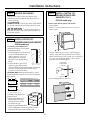
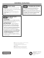
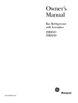
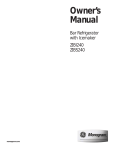
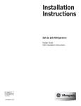
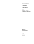
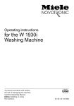
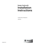
Design Guide with
Installation
Instructions
Double-Drawer Built-In Refrigerator
ZIDI240
ZIDS240
monogram.com
Safety Information
BEFORE YOU BEGIN:
WARNING:
Read these instructions completely and carefully.
• Double-Drawer Refrigerators are designed to be
built-in only. They cannot be used free-standing.
• Use this appliance only for its intended purpose.
• Immediately repair or replace electrical service cords
that become frayed or damaged.
• Unplug the unit before cleaning or making repairs.
• Repairs should be made by a qualified service
technician.
IMPORTANT – Save these instructions
for local inspector’s use.
IMPORTANT – Observe all governing codes
and ordinances.
Note to Installer – Be sure to leave these
instructions with the Consumer.
Note to Consumer – Keep these instructions with
your Owner’s Manual for future reference.
AVERTISSEMENT :
• Les réfrigérateurs à deux tiroirs sont conçus pour
être encastrés uniquement. Ils ne peuvent pas être
séparés.
• Il ne faut utiliser cet appareil que pour l’usage pour
lequel il a été construit.
• Il faut réparer ou remplacer immédiatement tout
cordon d’alimentation électrique effiloché ou
endommagé.
• Débrancher le bar ou le réfrigérateur a vin avant
le nettoyage ou toute intervention.
• Les réparations doivent être faites par un technicien
qualifié.
WARNING –
This appliance must be
properly grounded. See the section below.
AVERTISSEMENT –
Cet appareil doit être correctement mis à la terre.
Consulter la section au-dessous.
If you received a damaged Double-Drawer Refrigerator,
you should immediately contact your dealer or builder.
Skill Level – Installation requires basic mechanical
skills. Proper installation is the responsibility of the
installer. Product failure due to improper installation
is not covered under the GE Appliance Warranty.
For Monogram local service in your area, call
1.800.444.1845
For Monogram service in Canada, call
1.800.561.3344
For Monogram Parts and Accessories, call
1.800.626.2002.
www.monogram.com
GROUNDING THE DOUBLE-DRAWER
REFRIGERATOR
IMPORTANT – Please read carefully.
DO NOT, UNDER ANY
CIRCUMSTANCES, CUT
OR REMOVE THE THIRD
(GROUND) PRONG
FROM THE POWER CORD.
FOR PERSONAL SAFETY, THIS APPLIANCE MUST
BE PROPERLY GROUNDED.
The power cord of this appliance is equipped with
a three-prong (grounding) plug which mates with a
standard three-prong (grounding) wall receptacle to
minimize the possibility of electric shock hazard from
this appliance.
DO NOT USE AN ADAPTER PLUG
TO CONNECT THE REFRIGERATOR
TO A 2-PRONG OUTLET.
DO NOT USE AN EXTENSION
CORD WITH THIS APPLIANCE.
Have the wall outlet and circuit checked by a qualified
electrician to make sure the outlet is properly grounded.
Where a standard 2-prong wall outlet is encountered,
it is your personal responsibility and obligation to have it
replaced with a properly grounded 3-prong wall outlet.
2
Important Information
CONTENTS
Important Information
Tools, Hardware ........................................3
Parts Required..............................................3
Caring for Your Stainless Steel ............3
Design Guide (for ZIDI240)
The Installation Space ..............................5
Product Clearances....................................5
Side-by-Side Installations ......................5
Design Guide (for ZIDS240)
The Installation Space ..............................4
Product Clearances....................................4
Side-by-Side Installations ......................4
Installation Instructions
Step 1, Remove Packaging ....................6
Step 2, Install Custom 3/4″
Drawer Panels and Handles
(ZIDI240 model only) ............................6, 7
Step 3, Level ..................................................7
Step 4, Connect Power ............................8
Step 5, Slide Product into Cutout ........8
Step 6, Set Temperature Controls ......8
CARING FOR YOUR STAINLESS STEEL
ZIDI240 MODEL ONLY
PARTS REQUIRED
PARTS SUPPLIED
• Custom handles
• Overlay panels
• Spacer panels
• Backer panels
• Screws
• Drawer side trims
• Optional black or
stainless steel toekick
• Before installation or first use, we strongly advise you
polish the stainless steel exterior and handles with a
commercially available stainless steel cleaner such
as Stainless Steel Magic™. To preserve and protect
the fine finish, we also strongly advise that you
apply stainless steel cleaner monthly.
TOOLS REQUIRED
• Adjustable wrench
• Carpenter’s glue (ZIDI240 model only)
• Screwdriver (ZIDI240 model only)
3
Design Guide
FOR MODEL ZIDS240 WITH STAINLESS STEEL DRAWERS AND HANDLES
THE INSTALLATION SPACE
PRODUCT CLEARANCES
IMPORTANT: Double-Drawer Refrigerators are
designed to be built-in only. They cannot be used
free-standing.
When installed
in a corner:
Countertop
Double-Drawer
Locate
Outlet
8-1/2"
10-1/2"
34-1/2"-35"
24"
9"
9" Max.
Max.
22" min.
1-1/2"
1-1/2"
23-3/4" Min.
NOTE:
Handle and
handle standoff
depth is 2-1/8″
34-1/4"
to 34-3/4"
25-7/8"
Including
Handles
Clearance for Door
Opening 2-1/2" min.
Allow 2-1⁄2″ min. clearance between Double-Drawer
and adjacent cabinet, wall or other appliances.
Allow 22″ min. clearance from the front for drawer
opening.
NOTE: Clearances are based on the noted 2-1⁄8″
handle standoff depth.
• Test the drawer openings. Carefully open and close
the drawers. The drawers should not rub or catch on
adjacent cabinetry. Notify the installer if the drawers
make contact with cabinetry.
34-1/4"
to 34-3/4"
23-3/4"
The cutout depth should be 24″
NOTE: The unit is designed to be flush with the
surrounding cabinets.
Choose the location:
• These products may be closed in on the top and
three sides as long as the front is unobstructed for
air circulation and proper access to the drawers.
• Do not install these products where the temperature
will go below 55°F (13°C) or above 90°F (32°C).
• These products are not designed to be stacked one over
the other.
Additional Specifications
• A 120 volt 60Hz., 15 or 20 amp power supply is required.
An individual properly grounded branch circuit or circuit
breaker is recommended. Install a properly grounded
3-prong electrical receptacle recessed into the back
wall as shown. Electrical must be located on rear wall
as shown. NOTE: GFCI (ground fault circuit interrupter)
is not recommended.
SIDE-BY-SIDE INSTALLATIONS –
Stainless Steel Models Only
Locate
Outlet
10-1/2"
10-1/2"
14"
For a complete refreshment center, install a Double-Drawer
Refrigerator beside a Beverage Center, Wine Chiller/
Wine Reserve, Fresh-Food Refrigerator or Bar Refrigerator
with Icemaker.
• A side-by-side installation requires at least a 47-1/2″ wide
opening. No trim kits required.
• Products must operate from separate, properly grounded
receptacles.
34-1/2"-35"
15"
9"
9"
1-1/2"
47-1/2" Min.
4
24"
Design Guide
FOR MODEL ZIDI240 WITH CUSTOM DRAWER PANELS AND HANDLES
THE INSTALLATION SPACE
PRODUCT CLEARANCES
IMPORTANT: Double-Drawer Refrigerators are
designed to be built-in only. They cannot be used
free-standing.
When installed
in a corner:
Countertop
Double-Drawer
Locate
Outlet
8-1/2"
10-1/2"
34-1/2"-35"
24"
9"
9" Max.
Max.
23-1/8" min.
1-1/2"
1-1/2"
23-3/4" Min.
Clearance for Door
Opening 2-1/2" min.
34-1/4"
to 34-3/4"
NOTE: Handles
not supplied.*
24-7/8"
Allow 2-1⁄2″ min. clearance between Double-Drawer and
adjacent cabinet, wall or other appliances. Allow 23-1⁄8″
min. clearance from the front for drawer opening.
NOTE: Custom handle clearances may vary depending on
the standoff of the custom handles.
• Test the drawer openings. Carefully open and close
the drawers. The drawers should not rub or catch on
adjacent cabinetry. Notify the installer if the drawers
make contact with cabinetry. NOTE: When installing
custom panels and handles, use above clearances as
a general guide but adjust according to the installation.
23-3/4"
*Custom handle clearances may vary, depending on the
standoff of the custom handles.
The cutout depth should be 24″
The cutout dimensions shown allow for full drawer
extension.
NOTE: The drawers should be flush with the surrounding
cabinets.
Choose the location:
• These products may be closed in on the top and
three sides as long as the front is unobstructed for
air circulation and proper access to the drawers.
• Do not install these products where the temperature will
go below 55°F (13°C) or above 90°F (32°C).
• These products are not designed to be stacked one over
the other.
Additional Specifications
• A 120 volt 60Hz., 15 or 20 amp power supply is required.
An individual properly grounded branch circuit or circuit
breaker is recommended. Install a properly grounded
3-prong electrical receptacle recessed into the back
wall as shown. Electrical must be located on rear wall
as shown. NOTE: GFCI (ground fault circuit interrupter)
is not recommended.
Black or Stainless Steel Toekick Options
• These products are shipped with two toekicks,
a stainless steel and a black toekick. For shipping
purposes, one of the toekicks will be secured to
the back of the unit and the second will be installed,
in place, on the unit. Keep the unused toekick,
and other unused or removed parts, for future use.
SIDE-BY-SIDE INSTALLATIONS –
Custom Panel Models Only
Locate
Outlet
10-1/2"
10-1/2"
14"
For a complete refreshment center, install a Double-Drawer
Refrigerator beside a Beverage Center or Wine Chiller/
Wine Reserve.
• A side-by-side installation requires at least a 47-1/2″ wide
opening. No trim kits required.
• Products must operate from separate, properly grounded
receptacles.
34-1/2"-35"
15"
9"
9"
1-1/2"
47-1/2" Min.
*NOTE: Additional clearances
may be required.
5
24"
Installation Instructions
STEP 1 REMOVE PACKAGING
STEP 2 INSTALL CUSTOM 3/4″
DRAWER PANELS AND
HANDLES (CONT.)
• Remove corner blocks and foam drawer stops.
• Remove all packing material, tape and protective
plastic coverings.
(ZIDI240 model only)
CAUTION: Small objects are a choke hazard
Install custom drawer panels and handles:
• Open drawers.
• Remove 2 screws holding each trim; lift trims off.
Retain screws.
for children. Remove and discard any parts not used.
ATTENTION :
Les petits objets peuvent
étrangler les enfants. Il faut jeter toutes les piéces qui
ne sont pas utilisées.
STEP 2 INSTALL CUSTOM 3/4″
DRAWER PANELS AND HANDLES
(ZIDI240 model only)
3/4″ Overlay Panel Dimensions
Model ZIDI240 requires field-installed
overlay drawer panels.
Overlay
Panel
• The overlay panels must be secured
to 1/4″ thick backer panels that
Drawer
slide into the trims. A .10″ thick
spacer panel must be placed
between the overlay and backer
panels.
1/4"
.10 Inch
Backer
• Custom handles of your choice,
Spacer
Panel
supplied by your cabinet maker,
must be installed on these overlay panels. Countersink
all screws into the backer panels. Screws cannot
protrude from the backer panels.
IMPORTANT NOTE: Maximum total weight for custom
drawer panels are 25 pounds (12-1/2 pounds maximum
each drawer).
A
12-1/2 lbs. max.
B
*
12-1/2 lbs. max.
• Custom handles of your choice, supplied by your
cabinet maker, must be installed onto the overlay
panels before they are slid into the trims. Countersink
all screws into the backer panels. Screws cannot
protrude from the backer panels.
Screws Must
Be Countersunk
Into Panel
Handle
Custom
Drawer Panel
• Slide overlay panels into the trims.
3/4″ Overlay Panel Dimensions (in inches)
A (Width)
B (Height)
1/4″ Backer
23-3/16″
14-11/16″
0.10″ Spacer
22-1/2″
14-3/16″
3/4″ Overlay
23-5/8″
15-1/16″
B
*Maintain a 1/4″ min. gap between
top and bottom drawer panels.
Overlay Panel
Assemble overlay panels with
glue and screws.
Spacer Panel
• Center spacer panel on the
backer panel, left to right
and top to bottom. Secure
Backer Panel
the panels with glue.
• Center the spacer/backer panel
on the overlay panel. Secure with glue and screws.
Countersink all screws into the backer panel.
6
Installation Instructions
STEP 3 LEVEL
STEP 2 INSTALL CUSTOM 3/4″
DRAWER PANELS AND
HANDLES (CONT.)
Use an adjustable wrench to turn and raise or lower the
leveling legs.
• Measure floor to countertop height inside the opening.
Adjust leveling legs until the product is approximately
1/8″ less than countertop height.
(ZIDI240 model only)
• Reinstall the side trims using the trim screws removed
earlier.
Turn Right to Lower
Turn Left to Raise
• Place the brushed decorative covers over the side trim
to hide the screw heads. Ensure side trim is aligned top
to bottom and front to back. Snap into place.
NOTE: For shipping purposes, the brushed decorative
cover will be secured to the front of the unit.
INSTALLATION TIP:
Measure floor to underside of countertop inside
the opening.
• If the room floor is higher than the floor inside the
opening, adjust the rear leveling legs to approximately
1/8″ less than the opening height. Screw front leveling
legs all the way in to shorten the height at the front.
This will allow you to slightly tip the unit into the
opening. Once the unit is in the correct position,
the front legs can be adjusted to level the product.
7
Installation Instructions
STEP 4 CONNECT POWER
STEP 6 SET TEMPERATURE CONTROLS
• Connect power cord plug to a properly grounded
receptacle.
• Check to make sure power is on by opening a drawer
to see if interior light turns on.
• The interior fan runs all the time except when a
drawer is open.
See the Owner’s Manual for further explanation of
the fan.
• The temperature controls are preset. Refer to
the Owner’s Manual for more information. Allow
12–24 hours for the temperature to stabilize.
NOTE: The Double-Drawer Refrigerator operates very
quietly. You may not notice the unit running, and when
first installed, the fans and motor may not come on
immediately – this is normal. If the display is lit and
the light is working, the unit is operating.
STEP 5 SLIDE PRODUCT INTO
THE CUTOUT
CAUTION: Do not push against the drawer
panels with your knees. Do not push or lift the unit by
the drawer handles. Damage may occur!
ATTENTION :
Ne poussez jamais les
panneaux de tiroir avec vos genoux. Ne poussez
jamais votre appareil ou ne le soulevez jamais par
les poignées de tiroir. Vous pouvez l’endommager.
• Open one of the drawers and gently push the unit
back into the opening with your hands against the
sides. Be careful not to entangle power cord.
• Check again to be sure the unit is level. Adjust the
leveling legs until the unit is resting firmly against
the bottom of the counter to prevent rocking or
movement during operation.
• If alignment with adjacent cabinetry is an issue,
use a shim to secure the unit against the underside
of the countertop.
NOTE: While performing installations described in this book,
safety glasses or goggles should be worn.
For Monogram® local service in your area, call
1.800.444.1845.
NOTE: Product improvement is a continuing endeavor
at General Electric. Therefore, materials, appearance
and specifications are subject to change without notice.
Pub. No. 31-51545-2
Part No. 197D5893P003
08-07 JR
Printed in Slovenia
GE Consumer & Industrial
Appliances
General Electric Company
Louisville, KY 40225
ge.com