1
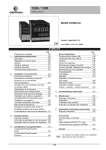
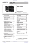
Installation
Instructions
If you have questions, call 1.800.GE.Cares (1.800.423.2737) or visit our website at GEAppliances.com in the
United States. In Canada, call 1.800.561.3344 or visit www.GEAppliances.ca.
15” Built-In Compactors
GCG1500 BB
GCG1500 WW
GCG1580 SS
GCG1700 II*
ZCGP150 II*
ZCGS150 SS
*For ZCGP150 II and GCG1700 II,
also refer to the instructions
provided on the template
packed with those models.
Safety Information
BEFORE YOU BEGIN
WARNING!
Read these instructions completely and
carefully.
Do not allow items to fall or collect behind the
compactor. Failure to follow this instruction
could result in a fire.
•IMPORTANT – Save these instructions for
local inspector’s use.
•IMPORTANT – Observe all governing codes
and ordinances.
• Note to Installer – Be sure to leave these
instructions with the Consumer.
• Note to Consumer – Keep these instructions with
your Owner’s Manual for future reference.
• Skill Level – Installation of this appliance requires
basic mechanical and electrical skills.
• Completion time – 1 hour.
• Proper installation is the responsibility of the
installer.
• Product failure due to improper installation is not
covered under the Warranty. See Owner’s Manual
for warranty information.
CAUTION:
For personal safety, remove house fuse or open
circuit breaker before beginning installation to
avoid severe or fatal shock injury.
While performing installations described in this
book, safety glasses or goggles should be
worn.
IMPORTANT
• This compactor is for household use only.
• Use this compactor only for its intended purpose.
• This compactor is designed for BUILT-IN
installations ONLY.
Installation Preparation
Electrical Requirements .................................................... 5
Grounding Requirements .................................................. 5
Unpacking the Compactor ................................................ 6
Replacing the Door Toekick................................................6
Leveling the Compactor...................................................... 7
Adjusting the Retaining Bracket .................................... 7
Adjusting the Base Toekick................................................ 7
CONTENTS
Design Information
Models Available .................................................................... 3
Product Dimensions and Clearances .......................... 3
Tools Required ........................................................................ 3
Parts Supplied ........................................................................ 3
Advance Planning
Clearances ................................................................................ 4
Models with a Custom Drawer Panel .......................... 4
Installation Instructions
Position the Compactor under the Countertop ...... 8
Attach the Compactor to the Countertop.................. 8
Reinstall the Compactor Drawer .................................... 9
Installation of the Trash Bag Caddy ............................ 9
Finalize Installation................................................................ 9
2
Design Information
MODELS AVAILABLE
*For ZCGP150 II and GCG1700 II, also refer
to the instructions provided on the template
packed with those models.
GCG1580 SS
GCG1500 BB
GCG1500 WW
GCG1700 II*
ZCGS150 SS
ZCGP150 II*
PRODUCT DIMENSIONS AND CLEARANCES
24”
(61 cm)
min.
15”
(38.1 cm)
min.
33-3/4”
(85.7 cm)
min.
to
35” (88.9 cm)
max.
34” (86.4 cm)
to
35” (88.9 cm)
Locate the outlet 18” (45.7 cm) min. from the
floor, 3” (7.6 cm) min. from either side
23” (58.4 cm)
14-7/8” (37.8 cm)
PARTS SUPPLIED
TOOLS REQUIRED
•Level
• Allow 23″ (58.4 cm)
clearance at the front for
a full drawer opening.
• Allow 6″ (15.2 cm)
clearance on the right
side to the nearest
vertical wall or cabinet
for bag removal.
• Note: This compactor is
designed for built-in
applications only.
• 6 mounting screws,
#8 x 11/16" (1.8 cm) long
•Gloves
• 2 countertop retaining
brackets
•Phillips screwdriver
• 2 side-mounting clips
•Measuring tape
•Pliers
Additional parts for ZCGS150SS and ZCGP150II
• Door toekick
• 8 Toekick screws,
#8 x 5/16" (0.8 cm) long
All parts are located in a package inside the drawer.
To order additional parts, call 800.626.2002 or visit
GEAppliances.com in the United States. In Canada,
call 1.800.561.3344 or visit www.GEAppliances.ca.
• Top toekick
• Base toekick
3
• 4 White mounting
screws, #8 x 11/16"
(1.8 cm) long
ADVANCE PLANNING
CLEARANCES
MODELS WITH A CUSTOM
DRAWER PANEL
• You should be able to fully open the compactor
drawer. Six inches (15.2 cm) is required on the
right side of the compactor for bag removal.
• Allow 23 inches (58.4 cm) in front of the
compactor to remove the drawer.
• This compactor is designed as a built-in
appliance only. It may be located in any
convenient space under a countertop.
DO NOT OPERATE FREE-STANDING.
• The compactor may be installed beneath
countertops of stone or other materials that will
not accept screws. No trim kit is required.
Models ZCGP150 II and GCG1700 II
The custom drawer panel and custom handle of
your choice should be secured to the compactor
before installation begins. A template with
instructions and installation hardware is provided
with those models. For planning purposes, you
may order the template in advance by calling
1.800.GE.CARES (1.800.423.2737) or by visiting our
website at GEAppliances.com in the United States.
In Canada, call 1.800.561.3344 or visit
www.GEAppliances.ca. Order Pub. No. 31-30597.
Complete panel installation instructions are included
on the template.
The compactor must be securely installed in a
cabinet that is firmly attached to the house
structure. Weight on the compactor drawer could
cause the compactor to tip and result in injury.
Never allow anyone to climb, sit or hang on the
compactor drawer.
CUSTOM PANEL SIZE REQUIREMENTS:
Maximum panel weight is 12 LBS (5.4 kg).
3/4”
(1.9 cm)
Thick
Custom
Panel
29-5/16”
(74.5 cm)
14-7/8”
(37.8 cm)
4
Installation Preparation
ELECTRICAL REQUIREMENTS
GROUNDING REQUIREMENTS (CONT.)
WARNING!
Grounding Instructions:
For your personal safety, this appliance must
be grounded while in use to reduce the risk of
electric shock. The appliance is equipped with
a three-conductor power supply cord and a
three-prong grounding-type plug to fit the proper
grounding-type receptacle. The green (or green and
yellow-colored) conductor in the cord is the grounding
wire. Never connect the green (or green and yellow)
wire to a live terminal.
This appliance is for use on a nominal 120-volt circuit
and has a grounding attachment plug as shown
in the figure below. Make sure that the appliance is
connected to an outlet having the same configuration
as the plug. No adapter should be used with this
appliance.
FOR PERSONAL SAFETY: Remove house
fuse or open circuit breaker before
beginning installation. Do not use an
extension cord or adapter plug with
this appliance.
• The power supply cord and plug should be
brought to a separate 15- or 20-ampere branch
circuit single grounded receptacle. The outlet
box should be located within reach of the 36"
(91.4 cm) power cord.
• This appliance must be supplied with 120V,
60Hz and connected to an individual properly
grounded branch circuit, protected by a 15- or
20-ampere circuit breaker or time-delay fuse.
• If the electrical supply does not meet the above
requirements, call a licensed electrician before
proceeding.
IMPORTANT: Observe all governing codes and
ordinances.
3-prong grounding-type wall receptacle
3-prong
grounding
plug
Power
supply
cord
GROUNDING REQUIREMENTS
WARNING!
The improper connection of the equipmentgrounding conductor can result in a risk of
electric shock. Check with a qualified
electrician or service representative if you
are in doubt that the appliance is properly
grounded.
• Electrical Ground is REQUIRED on this compactor.
• DO NOT ground to a gas pipe.
• DO NOT change the power supply cord plug. If it
does not fit the outlet, have a proper outlet
installed by a qualified electrician.
• DO NOT have a fuse in the neutral or grounding
circuit. A fuse in the neutral or grounding circuit
could result in an electrical shock.
• DO NOT use an extension cord with this
compactor.
Failure to follow these instructions could result in
death or serious injury.
Grounded outlet
Grounding
plug
Copies of the standards listed
may be obtained from:
* National Fire
Protection Association
Batterymarch Park,
Quincy, MA 02260
To minimize possible shock hazard, the cord must
be plugged into the proper mating three-prong
grounding-type wall receptacle, grounded in
accordance with the National Electrical Code
ANSI/NFPA70—latest edition* and all local codes and
ordinances.
If a mating wall receptacle is not available, it is the
personal responsibility and obligation of the customer
to have a properly grounded three-prong wall
receptacle installed by a qualified electrician.
5
Installation Preparation
1 UNPACKING THE COMPACTOR
2 REPLACING THE DOOR TOEKICK
(Optional for ZCGS150SS and
ZCGP150II Models Only)
• Move the compactor close to the installation
location.
• Use a section of the shipping carton to protect
the finished floor.
ZCGS150SS and ZCGP150II Models are supplied
with extra toekicks that can replace the toekicks
assembled on the compactor.
• Do not use the handle to lift the compactor.
• Remove all protective packaging materials such
as tape or shipping pads. Remove waxy residue
caused by shipping material with a mild solution
of liquid household cleaner and water.
• Lay the drawer on its side.
• Check that the power supply cord is attached to
the cord clip on the rear of the compactor.
• Remove 2 door toekick screws. Remove door
toekick.
• Remove 2 foot pedal screws on the side of
the drawer. Lift off the foot pedal.
• Install the new door toekick using the original
screws.
Cord clip
• Reinstall the foot pedal using the original screws.
See Step 5 for instructions on replacing the top
toekick and base toekick.
Door
Toekick
screw
Door
Toekick
screw
Door
Toekick
IMPORTANT: Use the shipping carton as a pad.
Do not slide the compactor across a finished floor.
Damage will occur.
Foot pedal
• Open the compactor drawer and remove any
shipping materials or other items shipped in the
drawer.
• Do not remove the compactor bag (if installed).
• Grasp the sides of the drawer and lift it out of the
compactor. Place the drawer on a protected
surface. The drawer can scratch a finished floor.
6
Installation Preparation
4 ADJUST THE RETAINING BRACKET
3 LEVELING THE COMPACTOR
• The top of the compactor should be at least 1/8″
(3 mm) from the top of the cabinet opening. You
can adjust the height of the compactor by turning
the screws on the front leveling legs and rear
wheels.
• Determine installation depth of the compactor
beneath the countertop.
• Adjust the position of the retaining brackets so
that the screws can meet the underside of the
countertop.
• Mounting clips are provided for stone or other
hard countertops that will not accept screws.
Retaining
bracket
Front leveling legs
Countertop
Rear wheels
• Place a level inside the compactor on the floor
of the cabinet.
5 ADJUSTING THE BASE TOEKICK
A toekick extension is supplied. It can be used to
cover any gaps from the bottom of the compactor
to the floor. ZCGS150SS and ZCGP150II Models are
also supplied with extra toekicks which can replace
the original toekicks assembled on the compactor.
• Use the leveling legs to adjust level front to back
and side to side.
• Remove the top toekick screws as shown. Lift off
top toekick piece.
• Loosen the base toekick screws, adjust to touch
the floor and tighten the screws. If replacing the
toekick, remove the screws and lift off the toekick.
Install the new toekick with the original screws.
• Reinstall the top toekick piece with the original
screws.
Top toekick
Base toekick
7
Loosen screw
on each side
Installation
7 ATTACH THE COMPACTOR TO
THE COUNTERTOP
6 POSITION COMPACTOR UNDER
THE COUNTERTOP
• Use two #8 x 11/16″ (1.8 cm) long mounting
screws to fasten each retaining bracket at the top
of the compactor to the underside of the
countertop.
WARNING!
When moving the compactor, use gloves to
protect and cushion your hands.
To protect the finished flooring, use a dolly to
move the compactor near the installation
location.
Failure to follow these instructions could
result in injury.
• Plug the power cord into a properly grounded
receptacle.
Retaining
bracket
Mounting
screws
• Carefully lift the front of the compactor slightly
and roll the unit into the cabinet opening.
• If the brackets cannot be attached to the
underside of the countertop, attach mounting
clips to the bracket. Fasten the compactor to the
cabinet front with mounting screws through the
mounting clips.
Retaining
bracket
Mounting
screw
Mounting clip
Lift here
8
Installation
8 REINSTALL THE COMPACTOR
DRAWER
9 INSTALLATION OF THE TRASH BAG
CADDY (on some models)
• Grasp the sides of the drawer. Carefully slide the
drawer into the compactor.
• Set the bag caddy into the drawer and hook the
prepunched holes in the caddy on the bag
retainer buttons.
• Set the trash bag into the bag caddy and fold
over.
• Hook the holes in the bag over the bag retainer
buttons.
Trash
bag
caddy
Bag retainer
buttons
10 FINALIZE THE INSTALLATION
•
•
•
•
•
Turn power on at the source.
Turn the knob to ON.
Make sure the drawer is fully closed.
Lift the foot pedal to start the cycle.
The ram will travel downward, reverse and return
to the starting position.
• The compactor will shut off automatically.
• The cycle should take less than 30 seconds.
• Refer to your Owner’s Manual for operating
instructions.
9
Notes
10
Notes
11
NOTE: While performing installations described in this book,
safety glasses or goggles should be worn.
NOTE: Product improvement is a continuing endeavor at
General Electric. Therefore, materials, appearance and
specifications are subject to change without notice.
GE Consumer & Industrial
Appliances
General Electric Company
Louisville, KY 40225
GEAppliances.com
Pub. No. 31-30256-1
206C1559P196
09-09 JR
Printed in China
Instructions
d’installation
Pour toute question, composez le 1.800.423.2737 (1.800.GE.CARES) ou visitez notre site Web à l’adresse
GEAppliances.com aux États-Unis. Au Canada, composez le 1.800.561.3344 ou visitez notre site Web
à l’adresse www.electromenagersge.ca)
Compacteur intégré
de 38 cm (15 po)
GCG1500 BB
GCG1500 WW
GCG1580 SS
GCG1700 II*
ZCGP150 II*
ZCGS150 SS
*Pour ZCGP150 II et GCG1700 II,
reportez-vous aussi aux
instructions sur le gabarit
fourni avec l’appareil.
Information sur la sécurité
AVANT DE
COMMENCER
AVERTISSEMENT !
Ne laissez pas d’objets tomber ou s’accumuler
derrière le compacteur. Le non-respect de ces
instructions pourrait provoquer un incendie.
Lisez attentivement et avec soin ces
instructions.
•IMPORTANT – Conservez ces instructions
pour l’inspecteur local.
MISE EN GARDE :
•IMPORTANT – Respectez tous les codes
•
•
•
•
•
•
Pour votre sécurité, retirez le fusible de
la maison ou ouvrez le disjoncteur avant
l’installation, pour éviter des blessures graves ou
même le décès pouvant être causé par un choc
électrique.
et les ordonnances en vigueur.
Note à l’installateur – Assurez-vous de laisser
ces instructions au client.
Note au client – Gardez ces instructions avec
votre manuel d’utilisation à titre de référence.
Compétences requises – L’installation de cet
appareil exige des compétences de base en
mécanique et en électricité.
Dureé de l’installation – 1 heure.
La qualité de l’installation est la responsabilité
de l’installateur.
Toute défaillance du produit à cause d’une
installation inadéquate n’est pas couverte par
la garantie. Consultez le manuel d’utilisation
pour l’information sur la garantie.
Portez des lunettes de sécurité pendant
l’exécution des travaux d’installation décrits
dans le présent manuel.
IMPORTANT
• Ce compacteur ne doit être utilisé qu’à des fins
domestiques seulement.
• Utilisez ce compacteur seulement aux fins prévues.
• Ce compacteur est conçu SEULEMENT pour des
installations ENCASTRÉES.
Préparation de l’installation
Exigences électriques ............................................................ 5
Exigences de mise à la terre .................................................. 5
Déballage du compacteur ...................................................... 6
Remplacement du panneau inférieur de porte ............ 6
Mise de niveau du compacteur ............................................ 7
Ajustement de la fixation de retenue ................................ 7
Ajustement du panneau inférieur........................................ 7
CONTENU
Conception
Modèles disponibles.............................................................. 3
Dimensions et dégagements du produit .................... 3
Outils nécessaires ................................................................ 3
Pièces fournies ...................................................................... 3
Planification préalable
Dégagements .......................................................................... 4
Modèles à panneau de tiroir personnalisé ................ 4
Instructions d’installation
Positionnement du compacteur sous le comptoir ...... 8
Fixation du compacteur au comptoir .............................. 8
Réinstallation du tiroir du compacteur ............................ 9
Installation du porte-sac d’ordures .................................... 9
Finalisation de l’installation .................................................. 9
2
Conception
MODÈLES DISPONIBLES
GCG1580 SS
GCG1500 BB
GCG1500 WW
GCG1700 II*
ZCGS150 SS
ZCGP150 II*
*Pour les modèles ZCGP150 II et GCG1700 II,
reportez-vous aussi aux instructions sur le gabarit
fourni avec ces appareils.
DIMENSIONS ET DÉGAGEMENTS DU PRODUIT
61 cm
(24 po)
min.
38,1 cm
(15 po)
min.
85,7 cm
(33 3/4 po) min.
à 88,9 cm
(35 po) max.
86,4 à 88,9 cm
(34 à 35 po)
• Prévoyez un dégagement
de 58,4 cm (23 po) à l’avant
pour l’ouverture complète
du tiroir.
• Prévoyez un dégagement
de 15,2 cm (6 po) du côté
droit jusqu’au mur vertical
ou à l’armoire la plus
proche pour retirer le sac.
• Remarque : ce compacteur
est conçu pour une
installation encastrée.
58,4 cm (23 po)
37,8 cm (14 7/8 po)
Placez la prise à 45,7 cm (18 po) ou plus du sol et à
7,6 cm (3 po) ou plus d’un côté ou de l’autre.
PIÈCES FOURNIES
OUTILS NÉCESSAIRES
•Niveau
• 6 vis de montage n° 8 x
11/16 po (1,8 cm) de long
•Gants
• 2 fixations de retenue
pour le comptoir
• 2 agrafes de montage
de côté
•Tournevis à tête Phillips
•Ruban à mesurer
Pièces supplémentaires pour les modèles ZCGS150SS et ZCGP150II
• 8 vis de panneau
• Panneau inférieur
inférieur n° 8 x 5/16"
de la porte
(0.8 cm) de long
•Pinces
Toutes les pièces se trouvent dans un emballage
à l'intérieur du tiroir. Pour commander des pièces
supplémentaires, composez le 800.626.2002
ou visitez GEAppliances.com aux États-Unis. Au
Canada, composez le 1.800.561.3344 ou visitez
www.GEAppliances.ca.
• Panneau supérieur
• Panneau inférieur
de base
3
• 4 vis de montage
blanches n° 8 x 11/16"
(1.8 cm) de long
Planification préalable
DÉGAGEMENTS
MODÈLES AVEC UN PANNEAU
DE TIROIR PERSONNALISÉ
• Vous devriez pouvoir ouvrir entièrement le tiroir
du compacteur. Il faut 15,2 cm (6 pouces) du côté
droit du compacteur pour retirer le sac.
• Prévoyez 58,4 cm (23 pouces) devant
le compacteur pour retirer le tiroir.
• Ce compacteur est conçu pour être encastré
seulement. On peut le placer dans tout espace
pratique sous un comptoir. NE L’UTILISEZ PAS
COMME MODÈLE AMOVIBLE.
• Le compacteur peut être installé sous les
comptoirs de pierre ou autres matériaux qui
n’acceptent pas les vis. Aucune trousse de
garniture nécessaire.
Modèles ZCGP150 II et GCG1700 II
Le panneau de tiroir et la poignée personnaliseé de
votre choix devraient être fixés au compacteur avant
le début de l’installation. Un gabarit avec instructions
et quincaillerie est fourni avec ces modèles. Vous
pouvez commander le gabarit à l’avance aux fins
de planification en composant le 1.800.423.2737
(1.800.GE.CARES) ou en visitant notre site Web à
l’adresse GEAppliances.com aux États-Unis. Au
Canada, composez le 1.800.561.3344 ou visitez notre
site Web à l’adresse www.electromenagersge.ca.
Commandez N° de pub. 31-30597. Des instructions
d’installation complète du panneau sont incluses
sur le gabarit.
Le compacteur doit être installé de manière sûre
dans une armoire solidement fixée à la structure
de la maison. Un poids sur le tiroir du compacteur
pourrait faire basculer le compacteur et causer des
blessures. Ne laissez personne grimper, s’asseoir ou
se tenir debout sur le tiroir du compacteur.
TAILLE DU PANNEAU PERSONNALISÉ :
Le poids maximum du panneau est de 5,4 kg (12 lb).
Panneau
personnalisé
d’une
épaisseur
74,5 cm
de 1,9 cm
(29 5/16 po)
(3/4 po)
37,8 cm
(14 7/8 po)
4
Préparation de l’installation
EXIGENCES ÉLECTRIQUES
EXIGENCES DE MISE À LA TERRE (suite)
AVERTISSEMENT !
Méthode de mise à la terre :
Pour votre sécurité, cet appareil doit être mis à
la terre afin de réduire au minimum les risques de
chocs électriques. Le cordon d’alimentation à trois
conducteurs de cet appareil est muni d’une fiche à
trois broches (mise à la terre) qui se branche dans une
prise de courant murale correctement mise à la terre.
Le conducteur vert (ou verre et jaune) du cordon
d’alimentation est le fil de mise à la terre. Ne branchez
jamais le fil vert (ou vert et jaune) à une borne sous
tension.
Cet appareil est conçu pour être alimenté par un
circuit d’une tension nominale de 120 volts, et son
cordon d’alimentation est muni d’une fiche de mise
à la terre, comme illustré dans la figure ci-dessous.
Assurez-vous de brancher la fiche de l’appareil dans
une prise de courant ayant la même configuration
que la fiche. Il ne faut jamais utiliser d’adaptateur pour
brancher cet appareil.
SÉCURITÉ PERSONNELLE : retirez les
fusibles ou ouvrez le disjoncteur avant
de commencer l’installation. N’utilisez pas
de rallonge ou de fiche d’adaptation avec
cet appareil électroménager.
• Le cordon d’alimentation et la fiche doivent être
branchés dans une prise simple avec mise à la
terre simple d’une capacité de 15 ou 20 ampères.
La boîte de sortie devrait se trouver à portée d’un
cordon de 91,4 cm (36 po).
• Cet appareil doit être alimenté par un courant
de 120 V, 60 Hz et branché à un circuit exclusif
mis à la terre correctement et protégé par un
disjoncteur de 15 ou 20 ampères ou un fusible
temporisé.
• Si l’alimentation électrique fournie ne répond pas
aux exigences précédentes, appelez un électricien
agréé avant de poursuivre.
IMPORTANT : respectez tous les codes et les
ordonnances en vigueur.
Prise murale à 3 broches avec mise à la terre
Prise de courant
mise à la terre
Fiche à 3 broches
avec mise à la terre
EXIGENCES DE MISE À LA TERRE
Cordon
d’alimentation
AVERTISSEMENT !
Broche de mise
à la terre
Une mauvaise connexion du conducteur
de mise à la terre de l’appareil pourrait
créer un risque de choc électrique.
Consultez un électricien qualifié ou un
représentant du service si vous n’êtes pas
certain que l’appareil est correctement
mis à la terre.
• Il FAUT une mise à la terre pour ce compacteur.
• N’effectuez PAS la mise à la terre à une conduite
à gaz.
• NE changez PAS le cordon d’alimentation. Si la
fiche n’entre pas complètement dans la prise,
faites installer une prise appropriée par un
électricien qualifié.
• N’installez PAS de fusible dans un circuit neutre
ou de mise à la terre. Un fusible dans un circuit
neutre ou de mise à la terre pourrait provoquer
un choc électrique.
• N’utilisez PAS de rallonge avec ce compacteur.
Le non-respect de ces instructions peut causer
de graves blessures ou la mort.
Vous pouvez obtenir
des copies des normes
indiquées de :
* National Fire
Protection Association
Batterymarch Park,
Quincy, MA 02260
Pour réduire au minimum les risques de chocs
électriques, la fiche doit être branchée dans une prise
de courant murale à trois alvéoles mise à la terre en
conformité avec la version la plus récente de la norme
ANSI/NFPA 70 du National Electrical Code et avec tous
les codes et ordonnances locaux en vigueur.
Si la prise de courant murale n’est pas appropriée, il
incombe au client de la faire remplacer par une prise
de courant murale à trois alvéoles adéquatement
mise à la terre et installée par un électricien qualifié.
5
Préparation de l’installation
1 DÉBALLAGE DU COMPACTEUR
2 REMPLACEMENT DU PANNEAU
INFÉRIEUR DE PORTE (facultatif
pour les modèles ZCGS150SS et
ZCGP150II seulement)
• Amenez le compacteur près de l’emplacement
de l’installation.
• Utilisez une section de la boîte d’expédition
pour protéger le fini du plancher.
Un panneau inférieur supplémentaire est fourni
avec les modèles ZCGS150SS et ZCGP150II pour
remplacer celui actuellement installé sur l’appareil.
• N’utilisez pas la poignée pour soulever
le compacteur.
• Retirez tout matériau d’emballage de protection
comme le ruban ou les coussins. Retirez le résidu
de cire du matériau d’expédition avec une solution
de détergent liquide doux et d’eau.
• Couchez le tiroir sur le côté.
• Vérifiez que le cordon est fixé à la bride du cordon
à l’arrière du compacteur.
• Enlevez les deux vis du panneau inférieur de
porte. Retirez le panneau inférieur de porte.
• Enlevez les deux vis de la pédale au côté du tiroir.
Retirez la pédale.
• Installez le nouveau panneau inférieur de porte
en utilisant les vis enlevées précédemment.
Bride de cordon
• Réinstallez la pédale en utilisant les vis enlevées
précédemment.
Pour connaître les directives pour remplacer le
panneau supérieur et le panneau inférieur de base,
reportez-vous à l’étape 5.
Vis du panneau
inférieur de
la porte
IMPORTANT : utilisez la boîte d’expédition comme
coussin. Ne glissez pas le compacteur sur un
plancher fini. Cela causera des dommages.
Panneau
inférieur de
la porte
• Ouvrez le tiroir du compacteur et retirez tout
matériau d’expédition et autres articles expédiés
dans le tiroir.
• Ne retirez pas le sac du compacteur (s’il y a lieu).
• Agrippez les côtés du tiroir et sortez-le du
compacteur. Placez le tiroir sur une surface
protégée. Le tiroir pourrait égratigner un
plancher fini.
6
Vis du panneau
inférieur de
la porte
Pédale
Préparation de l’installation
4 AJUSTEZ LA FIXATION DE RETENUE
3 MISE DE NIVEAU DU COMPACTEUR
• Le dessus du compacteur devrait être à au moins
0,31 cm (1/8 po) du dessus de l’ouverture de
l’armoire. Vous pouvez ajuster la hauteur du
compacteur en tournant les vis à l’avant des
pieds de nivellement et des roulettes arrière.
• Déterminez la profondeur de l’installation du
compacteur sous le comptoir.
• Ajustez la position des fixations de retenue pour
que les vis puissent atteindre le dessous du
comptoir.
• Les agrafes de montage sont fournies pour les
comptoirs de pierre ou autres surfaces dures qui
n’acceptent pas les vis.
Fixation
de retenue
Pieds de nivellement
avant
Comptoir
Roulettes arrière
• Placez un niveau à l’intérieur du compacteur sur
le plancher de la carrosserie.
5 AJUSTEMENT DU PANNEAU INFÉRIEUR
Une rallonge de panneau est fournie. Elle peut servir
à couvrir tous les écarts entre le bas du compacteur
et le plancher. Un panneau supplémentaire est
également fourni avec les modèles ZCGS150SS et
ZCGP150II pour remplacer le panneau inférieur
d’origine installé sur l’appareil.
• Retirez les vis du panneau supérieur tel qu’illustré.
Sortez le panneau supérieur.
• Utilisez les pieds de nivellement pour ajuster
le niveau de l’avant vers l’arrière et de gauche
à droite.
• Desserrez les vis du panneau de base, ajustez
pour toucher le plancher et resserrez les vis. Si
vous remplacez le panneau inférieur, enlevez les
vis et soulevez le panneau inférieur pour l’enlever.
Installez le nouveau panneau inférieur à l’aide
des vis enlevées précédemment.
• Réinstallez le panneau supérieur avec les vis
originales.
Panneau
supérieur
7
Panneau inférieur
de base
Desserrez la vis
de chaque côté
Installation
7 FIXATION DU COMPACTEUR
AU COMPTOIR
6 POSITIONNEMENT DU COMPACTEUR
SOUS LE COMPTOIR
• Utilisez deux vis n°8 x 11/16 po (1,8 cm) de long
pour installer chaque fixation de retenue situées
sur le dessus du compacteur au dessous du
comptoir.
AVERTISSEMENT !
En déplaçant le compacteur, portez des gants
pour protéger vos mains.
Pour protéger le fini du plancher, utilisez un
chariot pour déplacer le compacteur et le
rapprocher du site d’installation.
Le non-respect de ces instructions peut mener
à des blessures.
Fixation
de retenue
Vis de
montage
• Branchez le cordon dans une prise correctement
mise à la terre.
• Soulevez soigneusement l’avant du compacteur
et roulez l’appareil dans l’ouverture de l’armoire.
• Si les fixations ne peuvent pas être installeés
sous le comptoir, fixez les agrafes de montage
à la fixation. Fixez le compacteur à l’avant de
l’armoire avec les vis de montage à travers
les agrafes de montage.
Fixation
de retenue
Vis de
montage
Agrafe de
montage
Soulevez ici
8
Installation
8 RÉINSTALLATION DU TIROIR
DU COMPACTEUR
9 INSTALLATION DU PORTE-SAC
D’ORDURES (sur certains modèles)
• Placez le porte-sac dans le tiroir et accrochez les
trous prépercés dans le chariot sur les boutons
de retenue du sac.
• Agrippez les côtés du tiroir. Glissez avec soin
le tiroir dans le compacteur.
• Déposez le sac d’ordures dans le porte-sac
et repliez.
• Accrochez les trous du sac sur les boutons
de retenue du sac.
Porte-sac
d’ordures
ménagères
Boutons de
retenue du sac
10 FINALISATION DE L’INSTALLATION
•
•
•
•
•
Rétablissez le courant électrique.
Tournez le bouton de commande à ON (Marche).
Assurez-vous que le tiroir est bien fermé.
Soulevez la pédale pour amorcer le cycle.
Le coulisseau effectue une descente, puis
remonte et retourne à sa position initiale.
• Le compacteur s’éteint automatiquement.
• Le cycle doit durer moins de 30 secondes.
• Reportez-vous aux instructions de
fonctionnement du manuel d’utilisation.
9
Notes
10
Notes
11
REMARQUE : en exécutant les installations décrites dans
ce manuel, portez des lunettes de sécurité.
REMARQUE : General Electric cherche continuellement à
améliorer ses produits. Par conséquent, les matériaux
l'apparence et les spécifications peuvent être modifiés sans
préavis.
Pub. No. 31-30256-1
206C1559P196
09-09 JR
Imprimé en Chine