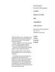
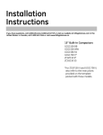
1
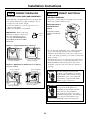
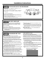
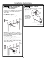
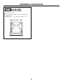
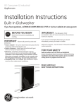
Installation
Instructions
If you have questions, call 800-GE-CARES or visit our website at: www.GEAppliances.com
Built-In Dishwashers
PDW8000, PDW8060
Design Guide with
Installation Instructions
GE Appliances
Safety Information
BEFORE YOU BEGIN
•
Read these instructions completely and carefully.
•
IMPORTANT
- Save these instructions for
local inspector’s use. Observe all governing
codes and ordinances.
• Note to Installer - Be sure to leave these instructions with the Consumer.
• Note to Consumer - Keep these instructions with
your Owner’s Manual for future reference.
•
If you received a damaged dishwasher, you should
immediately contact your dealer or builder.
READ CAREFULLY.
KEEP THESE INSTRUCTIONS.
FOR YOUR SAFETY
Skill Level – Installation of this dishwasher requires
basic mechanical and electrical skills. Proper installation is the responsibility of the installer. Product
failure due to improper installation is not covered
under the GE Appliance Warranty.
•
IMPORTANT –
The dishwasher MUST
be installed to allow for future removal from the
enclosure if service is required.
Read and observe all CAUTION and WARNINGS
shown throughout these instructions.
Completion Time – 1 to 2 Hours. New installations require more time than replacement installations.
CONTENTS
Installation Instructions
Step 1, Remove Packaging ...........................................10
Step 2, Install Leveling Legs ....................................... 10
Step 3, Remove Access Covers .................................... 10
Step 4, Install 90° Elbow ...............................................10
Step 5, Install Power Cord ............................................11
Step 6, Level Dishwasher ..............................................11
Step 7, Slide Dishwasher into Opening .......................11
Step 8, Connect Water Line ........................................ 11
Step 9, Connect Drain Line ........................................ 12
Step 10, Connect Electrical ......................................... 12
Step 11, Position and Level Dishwasher ......................13
Step 12, Pre-Test Check List ........................................ 13
Step 13, Dishwasher Wet Test ..................................... 13
Step 14, Secure Dishwasher
to Cabinet or Countertop ....................................... 14
Step 15, Install Toekick ................................................14
Step 16, Install Side Filler Strips ..................................15
Design Information
Product Dimensions .......................................................3
Models Available ............................................................ 3
Advance Planning .......................................................... 3
Installation Preparation
Materials You Will Need .................................................4
Tools You Will Need .......................................................4
Parts Supplied .................................................................5
Prepare Dishwasher Enclosure ..................................... 5
Drain Requirements .......................................................6
Prepare Electrical Wiring ...............................................7
Prepare Hot Water Line .................................................8
Custom Panel Dimensions
Custom Panels for PDW8000 ........................................ 9
2
Design Information
PRODUCT DIMENSIONS
ADVANCE PLANNING
• These dishwashers are designed for versatility,
adaptable to virtually any installation.
• All models have a full length door or a modified
door to accept a full cabinet panel without the
traditional access panel
• Side tub flange trim is adjustable and will conceal
any slight gap between the dishwasher and adjacent
cabinetry.
• These dishwashers may be installed beneath
countertops of stone or other materials that will not
accept screws. No trim kit required.
34"
Adjustable
to 35"
23-1/2"
23-5/8"
Standard installation in 24" deep cabinets
• In standard 24" deep cabinets, the dishwasher door
will be flush with adjacent cabinetry.
• Models with 3/4" thick custom door panel will fit
flush with adjacent cabinetry.
DISHWASHER MODELS
Traditional Built-In
PDW8000 BB, Black - Accepts 1/4" or 3/4" custom
panels
PDW8000 WW White - Accepts 1/4" or 3/4" custom
panels
PDW8000 CC Bisque - Accepts 1/4" or 3/4" custom
panels
Trim Kits
• GPF725W (white), GPF725B (black) or GPF725C
(bisque) custom panel kits, supports a 1/4" thick
custom door panel.
• ZPF675W (white), ZPF675B (black), ZPF675C
(bisque), custom panel kits support a 3/4" thick
custom door panel.
Stainless Steel Built-In
PDW8060 SS, Stainless steel door
Supplied or Custom Toekicks
• A 2-piece toekick is supplied with all models. The
toekick is height and depth adjustable.
• Depending on cabinetry style, a custom toekick can
also be installed to match cabinetry. Care must be
taken to assure door swing clearance above the
toekick.
ADA-Compliant
Installation below 34" high countertops
A reduced height installation (32-1/2" min.) beneath
a 34" countertop, can be accomplished by removing
the front leveling legs. The rear legs should be
screwed in flush with the bottom support, as shipped.
The front of the dishwasher must be shimmed to
level the dishwasher. Water and electrical must be
routed through the back wall.
3
Installation Preparation
MATERIALS YOU WILL NEED:
Materials Required for All Installations
Screw Type Clamps
¨ 90° Elbow (3/8”NPT external thread on one end, opposite
end sized to fit water supply)
Note: Use new ferrule. Do not use old parts.
¨ Strain relief for electrical connection
¨ Thread seal tape
¨ UL Listed wire connectors (3)
¨ Screw type hose clamps
90° Elbow
Thread Seal
Tape
Wire Nuts
Strain Relief
Materials For New Installations Only:
¨ Air gap for drain hose, if required
¨ Waste tee for house plumbing, if applicable
¨ Electrical cable or power cord, if applicable
¨ Hand shut-off valve (recommended)
¨ Water line 3/8” min. copper or 1/2” min. plastic (plastic
must be tested for temperature and pressure)
¨ Coupler for extending drain line, if applicable
Waste Tee
Air
Gap
TOOLS YOU WILL NEED:
For New Installations Only:
¨ Drill and appropriate bits
¨ Hole saw set
Electrical Cable
or Power Cord
Coupler
Hot Water Line
Flat Blade Screwdriver
Tools Required for All Installations
¨ Phillips head and flat blade screwdrivers
¨ 3/8”, 5/16” and 1/4” nutdrivers
¨ Level
¨ Carpenters square
¨ Measuring tape
¨ Safety glasses
Wire Strippers
¨ Flashlight
¨ Bucket to catch water when flushing the line
¨ Tubing cutter
¨ Gloves to protect against sharp edges
¨ Wire strippers
Shut-Off
Valve
Nut Driver
Phillips Head
Screwdriver
Tubing
Cutter
Safety Glasses
Flashlight
Adjustable
Wrench
Bucket
Drill
and Bits
Measuring Tape
Square
Hole
Saw Set
Level
Gloves
4
Installation Preparation
PARTS SUPPLIED:
Remove the hardware accessory bag and other parts
from inside or taped to the outside of the dishwasher.
Check contents against illustrations to insure that all
parts are included.
¨ 2-piece toekick
¨ 6 screws (see illustration)
¨ 2 leveling legs
¨ Junction box cover
Junction
Box Cover
with screws
2 Leveling Legs
ation
Insul
Screws A
(2) Countertop
Mounting
Screws
Screws B
(2) Cabinet
Mounting
Screws
Screws C
(2) Color
Matched
Toekick
Screws
2-Piece Toekick with
Sound Insulation
PREPARE DISHWASHER ENCLOSURE
34" to 35"
Underside
of Countertop
to Floor
This Wall Area
must be Free of
Pipes or Wires
1-3/4"
• The floor inside the opening must be even and level
with the finished floor of the kitchen. If the kitchen
floor is tile, it may be
higher than the floor of
the installation cutout.
Pieces of wood may be
placed into the cutout
floor to make it level or
higher than the room
20-1/2"
floor. This will allow easy
removal for any future
service.
24"
Min.
6"
23-5/8" Min.
24" Max
• The rough cabinet opening must be at least 24" deep,
23-5/8" min. to 24" wide. The height should be 34" min.
and 35" max.
Corner Installation
• When installing into a
corner, allow 2" min.
clearance between
dishwasher and adjacent
cabinet or wall.
• Allow 24-1/2" min. clearance
from the front of the
dishwasher for door
opening.
Note: ADA installation, beneath 34" high countertops may be accomplished by removing front leveling legs. Drain hose, water and
electrical must be routed through the cutout on the back of the
dishwasher.
• The dishwasher must be installed so that drain hose is
no more than 10 feet in length for proper drainage.
• The dishwasher must be fully enclosed on the top, sides
and back, but should not support any part of the
enclosure.
Countertop
Dishwasher
24-1/2"
Clearance for Door
Opening 2" Minimum
5
Installation Preparation
DRAIN REQUIREMENTS
Method 1 – Air Gap with Waste Tee or Disposer
An air gap must be used when the waste tee or disposer
connection is less than 18” from the floor.
• Follow local codes and ordinances.
• Do not exceed 10 feet distance to drain.
• To prevent back flow into the dishwasher, connect
drain line to an air gap or use a 30” high drain loop,
depending on local codes.
• Air gap must be used when waste tee or disposer
connection is less than 18” above the floor to prevent
siphoning.
DETERMINE DRAIN METHOD
The type of drain installation depends on the following
questions.
■ Do local codes or ordinances require an air gap?
■ Will waste tee or disposer connection be less than 18”
above the floor?
■ Will installation have a high drain loop less than 30”
above the floor?
If the answer to ANY of these questions is YES, Method 1
MUST be used.
• If all answers are NO, either method may be used.
Method 2 – High Drain Loop with Waste Tee or
Disposer Install waste tee or disposer and air gap according
to manufacturer’s instructions.
30"
12" Min.
Min.
30"
Min.
18"
Min.
CABINET PREPARATION
• Drill a 1-1/2” dia. hole in the cabinet wall within
the shaded areas shown for the drain hose connection. The hole should be smooth with no sharp
edges.
An air gap MUST BE USED if the drain hose is connected to a waste tee or disposer lower than 18” above
the floor level.
• Failure to provide the proper drain connection using
an air gap or a 30” min. high drain loop will result in
improper draining of the dishwasher which may cause
damage or poor wash performance.
PRUDENCE
Il DOIT Y AVOIR une coupure antirefoulement si le
tuyau de vidange est branché sur un raccord d’égout ou
un broyeur d’ordures à moins de 46␣ cm (18 po) du sol.
• Si la vidange n’est pas branchée correctement en
utilisant une coupure antirefoulement ou un boucle
d’égout d’au moins 76 cm (30 po) de haut,
l’écoulement de l’eau du lave-vaisselle n’est pas bon,
ce qui peut causer des dommages ou un mauvais
lavage de la vaisselle.
6
Installation Preparation
PREPARE ELECTRICAL WIRING
FOR PERSONAL SAFETY: Remove
house fuse or open circuit breaker
before beginning installation. Do not use
an extension cord or adapter plug with
this appliance.
Alternate
Receptacle
Location
18"
18"
6"
AVERTISSEMENT POUR ASSURER LA SÉCURITÉ
PERSONNELLE, il faut enlever le fusible
ou couper le courant au disjoncteur
avant de commencer l’installation. Avec
cet appareil, il ne faut pas utiliser de
rallonge ni d’adaptateur de prise.
Receptacle
Location
Area
1-1/2" Dia. Hole (Max.)
3"
from
2"
Cabinet
6"
2"
24"
from Wall
Ground
Black
White
Electrical Connections to Dishwasher:
The dishwasher junction box is located on the right side
at the front of the dishwasher. The electrical cable must
extend forward at least 24” to reach the junction box
when dishwasher is installed.
• The wiring may enter the opening from either side,
rear or the floor within the shaded area.
• Cut a 1-1/2” max. dia. hole to admit the electrical
cable or use the same hole cut for the drain hose. The
hole must be free of sharp edges. If the cabinet wall is
metal, the hole edge must be covered with a bushing.
• For power cord connections, install a 3-prong grounding type receptacle in the sink cabinet rear wall, 6"
min, or 18" max. from the opening, and 6" to 18"
above the floor.
Electrical Requirements
• This appliance must be supplied with 120V, 60 Hz., and
connected to an individual properly grounded branch
circuit, protected by a 15 or 20 ampere circuit breaker or
time delay fuse.
• Wiring must be 2 wire with ground and rated for 75°C
(176°F).
• If the electrical supply does not meet the above requirements, call a licensed electrician before proceeding.
Grounding Instructions–Cable Direct
This appliance must be connected to a grounded metal
permanent wiring system, or an equipment-grounding
conductor must be run with the circuit conductors and be
connected to the equipment-grounding terminal or lead
on the appliance.
Grounding Instructions–Power Cord
This appliance must be grounded. In the event of a
malfunction or breakdown, grounding will reduce the risk
of electrical shock by providing a path of least resistance
for electric current. The plug must be plugged into an
appropriate outlet that is installed and grounded in
accordance with all local codes and ordinances.
AVERTISSEMENT Le mauvais branchement du fil de mise à
la terre de l’équipement peut causer un
choc électrique. En cas de doute sur la
mise à la terre de l’appareil, consulter un
électricien qualifié ou un représentant
technique.
The improper connection of the equipment-grounding conductor can result in
a risk of electric shock. Check with a
qualified electrician or service representative if you are in doubt that the appliance is properly grounded.
7
Installation Preparation
PREPARE HOT WATER LINE
The line may enter from either side, rear or floor
within the shaded area shown.
• The water line may pass through the same hole as
the electrical cable and drain hose. Or, cut an
additional 1-1/2" dia. hole to admit the line. If a
power cord with plug is used, it must pass through
a separate hole.
Shut-off Valve 1-1/2"
Dia.
Hole
Right Side Entry
Approx. 40"
from Wall
1-3/4"
Hot
Water Line Connection
• Turn off the water supply.
• Install a hand shut-off valve in an accessible location, such as under the sink. (Optional, but strongly
recommended and may be required by local codes.)
• The hot water line should be 3/8” O.D. copper
tubing or 1/2” O.D. plastic tubing. The line must
extend forward at least 30" from the left side or 40"
from the rear wall.
• The water line must be long enough to form a
smooth natural loop with no sharp bends or kinks
between the cutout entry.
6"
Cabinet Face
Left
Side Entry
Approx. 30"
from Wall
2" from Floor
• Adjust water heater to deliver temperatures of 120°F to
150°F.
• Flush water line to clean out debris.
• The hot water supply line pressure must be 20-120 PSI.
8
Custom Panel Dimensions
3/4" PANEL WITH ZPF675 TRIM KIT
CUSTOM PANEL FOR MODELS
PDW8000
The custom panel size varies depending on your
installation.
Panel kits must be ordered separately. Installation
of any custom panel should be completed before
the dishwasher is installed.
Custom
Panel Size
Countertop
Cabinets
1/4" PANEL WITH GPF725 TRIM KIT
A
Floor
1/4"
Radius
Cut
1/4" Thick
Door Panel
Bottom of 3/4" Max.
Adjacent Cabinetry
25-1/4"
Top
3/4" Thick
Door Panel
*Height
23-1/8"
* Height is equal to A minus 5-3/8"
EXAMPLE: A = 30-1/2" minus 5-3/8" is equal to 25-1/8".
1. Measure Dimension A, from underside of countertop
to bottom of adjacent cabinets.
2. Subtract 5-3/8”. Control panel height is 5-1/8". Allow
1/4" clearance between countertop and control
panel.
3. The custom panel fits against bottom of the control
panel.
23-1/8"
• Cut the panel to the dimensions shown.
• The bottom left and right corners should be cut at
1/4" radius. See illustration.
9
Installation Instructions
STEP 3 REMOVE ACCESS COVER
BEFORE YOU BEGIN:
CUSTOM PANEL INSTALLATION: If you intend to
install custom door panels, (on some models) refer to
trim kit installation instructions. Custom panels should
be in place before installing the dishwasher.
Insulation Board
STEP 1 REMOVE PACKAGING
Cut the shipping carton and use it as a pad beneath the
dishwasher. This will protect the finished floor in the
kitchen.
• Remove wrapping and uncoil the drain hose in the
back of the dishwasher. Do not remove rear insulation
blanket.
• Lay the dishwasher on it’s back. Do not kink or crush
the drain hose.
Junction Box
Access Cover
• Remove sound insulation board and the access cover
plate.
• Install UL listed strain relief on junction box.
STEP 2 INSTALL LEVELING LEGS
1-1/4" Min.
STEP 4 INSTALL 90° ELBOW
Remove
Red Plugs
Rear
Insulation
Blanket
Unscrew
Rear Legs to
Installation
Height
90°
Elbow
• Measure installation opening from the floor to the
bottom of the countertop.
• Install the front leveling legs into holes on the brackets. Use a wrench to screw the legs in until the overall
height of the dishwasher is 1/4" less than the installation opening height.
Note: Install the legs as shown, 1-1/4" min from the
bottom of the bracket.
• Remove and discard the red plugs from the front
holes.
Thread
Seal Tape
• Install the 90° elbow onto the water inlet. Use thread
seal tape or pipe thread compound. Thread seal tape
should be wrapped in same direction as the threads on
the elbow.
• The 90° elbow should face the inlet water line.
10
Installation Instructions
STEP 5 INSTALL POWER CORD
STEP 7 SLIDE DISHWASHER
INTO OPENING
SKIP THIS STEP IF DISHWASHER
WILL BE DIRECT WIRED
DO NOT PUSH AGAINST THE FRONT PANEL WITH
KNEES, DAMAGE WILL OCCUR!
• Insert drain hose into the cabinet wall hole. If a power
cord is used, guide the end through a separate hole.
• Maximum power cord length is 6 ft.
• The power cord and connections must comply with
the National Electrical Code, Section 422 and/or
local codes and ordinances.
Insert power cord wires
through strain relief and
tighten.
Ground
White
Black
• Position water supply line and house wiring on the
floor of the opening to avoid interference with base
of dishwasher.
• Slide dishwasher into the opening a few inches at a
time. As you proceed, pull the drain hose through the
cabinet wall under the sink.
• Check to be sure there is no interference with
waterline or house wiring.
• Again, check to be sure the dishwasher is level.
• Strip 1/2" insulation
from ends of power
cord wires.
• Connect incoming power cord white to dishwasher
white, black to black and ground to dishwasher green
wire. Use UL listed wire connectors of appropriate size.
• Install junction box cover with screws provided. Be sure
wires are not pinched under the cover.
STEP 6 LEVEL DISHWASHER
STEP 8 CONNECT WATER LINE
• Carefully, upright the dishwasher, be careful not to
bend the leveling legs.
• Check to be sure the dishwasher is level and is
adjusted to fit the installation cutout height.
NOTE: If you are using an existing water line, cut 1" off
the end. Always use a new ferrule and compression nut.
• The water supply line should be flushed to clear any
foreign material before connecting to the dishwasher.
• Make sure there are no sharp bends or kinks to restrict
water flow.
• Insert water line into the 90° elbow.
• Slide ferrule against
Compression Nut
elbow and secure with
Ferrule
compression nut.
• Replace access panel
plate.
Level
Top
and
Sides
Hot Water
90° Elbow Supply Line
11
Installation Instructions
STEP 9 CONNECT DRAIN LINE
STEP 10 CONNECT ELECTRICAL
FOLLOW ALL LOCAL CODES AND ORDINANCES.
FOR DIRECT WIRE ONLY
(If a power cord with plug is used, plug it into the wall
outlet and continue with next step.)
• The dishwasher is supplied with a 72" long drain hose.
• If a longer drain hose is required, add up to 48” of
length for a total of 10 ft. length.
• Secure the drain hose to the air gap, waste tee or
disposer with clamps.
• Make sure drain hose is not kinked.
IMPORTANT: When connecting
drain line to disposer, check to be
sure that drain plug has been
removed. DISHWASHER WILL
NOT DRAIN IF PLUG IS LEFT
IN PLACE.
Verify that power is
turned off at the
source.
Ground
Insert power cord wires
through strain relief and
tighten.
Remove
Plug
White
Black
Method 1 – Air gap with waste tee or disposer
Waste Tee Installation
• Locate the three dishwasher wires, (white, black and
green) with stripped ends. Insert wire through the
small hole in the junction box. Use wire connectors to
connect incoming ground to green, white to white and
black to black.
• Install junction box cover with screws provided. Check
to be sure that wires are not pinched under the cover.
• Reinstall Insulation Board in position. The board
should be secured so it does not interfere with door
opening.
Disposer Installation
Method 2 – High drain loop with waste tee or disposer
Waste Tee Installation
Fasten to underside
of countertop
30"
12" Min.
Min.
Waste Tee Installation
Fasten to underside
of countertop
If house wiring is not 2-wire with
ground, a ground must be provided
by the installer. When house wiring is
aluminum, be sure to use UL Listed
anti-oxidant compound and aluminum-to-copper connectors.
30"
12" Min.
Min.
Disposer Installation
AVERTISSEMENT Si l’installation électrique de la maison
n’est pas à deux fils plus terre,
l’installateur doit installer un fil de
mise à la terre. Si l’installation
électrique de la maison est en aluminium, il faut prendre soin d’utiliser
des composés antioxydants et des
connecteurs aluminium à cuivre sur la liste UL.
12
Installation Instructions
STEP 11 POSITION AND LEVEL THE DISHWASHER
• Check to be sure the dishwasher is adjusted to correct
height and is centered in the cutout.
• Open and close the door to insure proper operation of
the door. If there is any binding or rubbing, readjust
leveling legs.
Door Rub Door Rub
On Right On Left
Hand Side Hand Side
CRE
NS
W
NS
U
U
Use a wrench to make adjustments.
• If the door rubs on the right side of the cabinet, extend the left rear
leg by unscrewing it one quarter turn.
• If the door rubs against the left side of the cabinet, extend the right
rear leg by unscrewing it one quarter turn.
• Check level again. Repeat the procedure if necessary.
Adjust
This
Leg
W
Adjust
This
Leg
CRE
STEP 12 PRE-TEST CHECK LIST
¨ Verify water supply and drain lines are not kinked or in contact
with other components.
¨ Turn on the sink hot water faucet and verify water temperature.
Incoming water temperature must be between 120°F and 150°F.
120°F min. temperature is required for best wash performance.
¨ Turn on water supply.
¨ Open the door. Check to be sure Insulation Board does not
interfere with door opening.
Installation service calls are not covered by your
warranty. To avoid unnecessary charges, review
this list carefully.
¨ Check to be sure power is OFF.
¨ Open the door and remove all foam and paper packaging.
¨ Pull lower rack out, about half way. Check to be sure it does
not roll back or forwards on the door. If the rack moves,
adjust leveling legs.
CHECK WATER FILL LEVEL
STEP 13 DISHWASHER WET TEST
¨ Turn on power supply.
¨ Select the normal cycle and press the start button.
¨ The control will indicate a slow/no fill by flashing the CHINA
CRYSTAL, LIGHT WASH OR WASH CYCLE light. Check water
supply, then adjust fill time according to the chart shown.
¨ Check to be sure that water enters the dishwasher, wait up to
2 minutes. If water does not enter the dishwasher, check to be
sure that water is turned on.
¨ Check for leaks under the dishwasher. If a leak is found, turn
power and water off, then tighten connections. Restore power
and water supply.
¨ Check for leaks around the door. A leak around the door could be
caused by door rubbing or hitting against adjacent cabinetry.
Reposition the dishwasher if necessary.
¨ After the dishwasher drains check drain lines. If leaks are found,
turn power off, correct as necessary.
¨ The control will indicate a slow/no drain by flashing the RINSE
ONLY, SANI WASH or HEAT OPTIONS. Check that the airgap is
clear of debris and that the knockout in the disposer or waste tee
is fully removed. Check that the drain hose is not kinked.
¨ Open the dishwasher door and make sure that most of the water
has drained. If not, check that disposer plug has been removed
and that air gap is not plugged.
¨ Cancel the dishwasher cycle and complete the installation.
¨ Remove protective film if present from the control panel and door.
13
For best performance, check the water fill level.
Run through a complete RINSE ONLY cycle to ensure it is emptying
and filling correctly. For low water pressure situations run the
RINSE ONLY cycle 3 times. Half-way through the final RINSE ONLY
cycle, pause the dishwasher and check the water level inside the
dishwasher. If the water level is not above the minimum water level
(marked on the lower spray support tower), increase the fill level.
1. Ensure the dishwasher is not running through a cycle. Depress
the WATER TEMP button for 10 seconds until the second buzzer
sounds (except on ZBD6600).
2. Press the START/CANCEL button to select fill time, as per chart
(65 seconds is the factory setting).
3. To test time, press DELAY START. The dishwasher will start filling.
Listen for the dishwasher to complete filling. Once filled, the fill
level must be checked to ensure fill time is correct.
4. Once complete, press the WATER TEMP button to exit fill time
mode.
Continue to press the START/CANCEL button
until the desired indicator is illuminated.
Cycle Statue Indicators Fill Time
SENSING
60 seconds
WASHING
65 seconds
RINSING
70 seconds
DRYING
80 seconds
CLEAN
90 seconds
Installation Instructions
STEP 14 SECURE DISHWASHER
TO CABINET AND
COUNTERTOP
STEP 15 INSTALL TOEKICK
• Loosen depth adjustment screws inside the bracket.
• Slide bracket out
to proper depth.
Tighten screws.
Adjust to
• Attach supplied
Toekick
toekick to
Depth
brackets with
screws C provided.
Do not tighten.
• Adjust the toekick
to touch the floor.
Tighten screws.
To maintain position and alignment, it is recommended
the dishwasher be secured to the countertop and
adjacent cabinets.
Secure dishwasher to countertop:
• Drill pilot holes through the mounting bracket and
into the underside of the countertop. Secure with
screws A provided.
Screw A
Attachment Screws
Adjust to Touch Floor
IMPORTANT: To avoid damage to your dishwasher,
drive screws straight and flush. Protruding screw heads
may scratch the top of the escutcheon or door and can
interfere with door closing.
Secure dishwasher to adjacent cabinets:
• Remove plastic plugs button on the inside of the
dishwasher frame. One on each side.
• Drill pilot holes through the dishwasher holes and
into the adjacent cabinets. Install screws B provided.
• Replace plastic plug buttons.
Plug Buttons
Screw B
14
Installation Instructions
STEP 16 ADJUST SIDE
FILLER STRIPS
• Open the door fully.
• Loosen (but do not remove) screws holding the top
and side trims.
• Adjust trim to cover opening gap. Tighten screws.
Adjust Side Trim
to Meet Cabinetry
Loosen
Screws
15
Note: While performing installations described in this book,
safety glasses or goggles should be worn.
Note: Product improvement is a continuing endeavor at
General Electric. Therefore, materials, appearance and
specifications are subject to change without notice.
0616 400 350
Pub. No. 31-30545
Dwg. No. 203C1559P085
(N.D. 318) 11/01