1
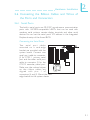
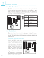
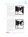
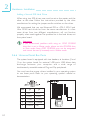
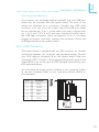
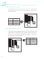
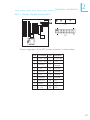
Hardware Installation 2 2.6.4 Floppy Disk Drive Controller 1. Install the 34-pin header connector into the shrouded floppy disk header (J11) on the system board. The colored edge of the ribbon should be aligned with pin 1 of connector J11. 2. Install the other 34-pin header connector(s) into the disk drive(s). Align the colored edge of the daisy chained ribbon cable with pin 1 of the drive edge connector(s). The end-most connector should be attached to the drive you want to designate as Drive A. 2.6.5 IDE Hard Disk Interface 1. If you are connecting two hard drives, install the 40pin connector of the IDE cable into the primar y shrouded IDE header (connector J12). If you are adding a third or four th IDE device, install the 40pin connector of the other IDE cable into the secondary shrouded IDE header (connector J10). 2. Install the other 40-pin header connector(s) into the device with the colored edge of the ribbon cable aligned with pin 1 of the drive edge connector(s). Note: Refer to your disk drive users manual for information about selecting proper drive switch settings. 23