1
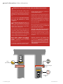
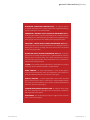
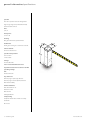
1601/1602 barrier gate operator - installation guide
barrier gate operator installation guide
for use with models
1601-080/081
1602-080/081
with circuit board 1601-010 rev. V or higher
general information
safety information .....................................................................................................4
glossary ........................................................................................................................5
specifications ..............................................................................................................6
operator installation
supplemental manual available
(P/N 2340-065) for 1601-081, 1601-088
and 1602-081 for optional battery
backup system with additional wiring
information.
DKS DoorKing, Inc.
120 Glasgow, Avenue
Inglewood, Ca. 90301
310.645.0023
310.641.1586 fax
www.doorking.com
[email protected]
surface operator ........................................................................................................7
electrical installation
main terminal wiring ................................................................................................9
high voltage wiring..................................................................................................10
low voltage wirng ....................................................................................................11
primary/secondary control wiring.......................................................................12
pams wiring ...............................................................................................................13
gate tracker wiring ...................................................................................................14
loop detector wiring ................................................................................................15
entry lane application .............................................................................................16
exit lane application ................................................................................................17
ticket spitter application ........................................................................................18
two-way lane application .......................................................................................19
timer down application ..........................................................................................20
copyright © 2006 DoorKing, Inc.
All rights reserved.
arm installation
notice of rights
The content in this manual is protected
under copyright law and no portion
of this manual may be copied,
reproduced, translated, or converted
to any electronic medium without prior
written consent.
settings
notice of liability
DoorKing, Inc. reserves the right to make
changes in the products described
in this manual without notice and/or
obligation to notify any persons of any
revisions or changes. DoorKing, Inc.
makes no representations or warranties
with respect to this manual.
publication number
1601-065-M-05-07
1601-065-M-05-07
hub ...............................................................................................................................21
aluminum-plastic-wood .........................................................................................22
wishbone ....................................................................................................................23
control board .............................................................................................................24
magnetic limit ...........................................................................................................25
direction check .........................................................................................................26
reverse sensitivity .....................................................................................................27
switch descriptions & functions ...........................................................................28
accessory installation
reversing edge ..........................................................................................................29
fan kit ...........................................................................................................................30
heater kit .....................................................................................................................31
technical information
wiring diagram ..........................................................................................................32
wiring diagram-convenience open .....................................................................33
maintenance schedule ............................................................................................34
troubleshooting ........................................................................................................35
accessories .................................................................................................................36
save this installation guide for reference
general information/safety information
Reduce the risk of injury or death, read and follow all instructions.
Familiarize yourself with safety warnings, instructions, illustrations, and wiring
guidelines to ensure that the installation is
performed in a safe and professional manner.
Prior to installation check all local building codes and ordinances to ensure
compliance.
Speed limit through barrier area is 5
MPH. Install speed bumps and warning
signs where visible in the area of the gate,
failure to do so may result in injury, damage to operator and vehicle.
Users should be familiar with proper use
of operator, these include; hardware operation, reversing functions and testing,
reversing loops, inherent reversing system,
electric edges, photoelectric cells related
external devices and possible hazards.
Keep adults, children and objects
away from operator and HAZARD
ZONES. Pedestrians must be provided
with a separate access.
All electrical connections should be made
in accordance with local electrical codes.
Controls must be installed away from the
operator (min. 10’ ft. away) to avoid any
contact when operating the controls. If
the installed hardware is in violation of
these restrictions remove the operator
from service immediately and contact
your service dealer.
When removing the operator lift the arm
to the full open position and shut off
power at the service panel.
Operators and components should be
properly installed and maintained following the recommended service schedule, test the operator monthly. Contact
your service dealer for any maintenance
or repairs.
Vehicular operators can produce high
levels of force, it is important that you
are aware and eliminate possible HAZARDS; Pinch Points, Entrapment, Absence of Controlled Pedestrian Access,
Traffic Backup.
3PEED"UMP
1610
Speed Bumps
Security features should be installed to
avoid unauthorized use.
Operator Danger
Zone
3PEED"UMP
SP
E
LIMED
IT
5
Speed Limit
Sign
4 installation guide
1601-065-M-05-07
general information/glossary
RESIDENTIAL VEHICULAR OPERATOR-CLASS - A vehicular operator
(or system) intended for use in a home of one-to-four single family dwelling,
garage or parking area associated therewith.
COMMERCIAL / GENERAL ACCESS VEHICULAR OPERATOR-CLASS II A vehicular gate operator (or system) intended for use in a commercial location
or building such as a multi-family housing unit (five or more single family units),
hotels, garages, retail store or other building servicing the general public.
INDUSTRIAL / LIMITED ACCESS VEHICULAR OPERATOR-CLASS III - A
vehicular gate operator (or system) intended for use in an industrial location or
building such as a factory or loading dock area or other locations not intended
to service the general public.
RESTRICTED ACCESS VEHICULAR OPERATOR-CLASS IV - A vehicular
gate operator (or system) intended for use in a guarded industrial location or
building such as an airport security area or other restricted access locations
not servicing the general public, were unauthorized access is prevented via
supervision by security personnel.
SYSTEM - In the context of these requirements, a system refers to a group of
interacting devices intended to perform a common function.
WIRED CONTROL - A control implemented in a form of fixed physical
interconnections between the control, associated devices and an operator to
perform predetermined functions in response to input signals.
WIRELESS CONTROL - A control implemented in means other than fixed
physical interconnections (such as radio waves or infrared beams) between
the control, the associated devices and an operator to perform predetermined
functions in response to input signals.
INHERENT ENTRAPMENT SENSOR SYSTEM - An automatic sensor system
that senses entrapment of a solid object and is incorporated as a permanent
and integral part of the operator.
ENTRAPMENT - The condition when an object is caught or held in a position
that increases the risk of injury.
1601-065-M-05-07
installation guide
5
general information/specifications
operator
The 1601 operator has been designed for
high usage single lane (14 feet maximum)
vehicular traffic control.
class:
II, III, IV
horsepower:
1/2 or 1 HP
housing:
G90 galvanized steel, painted white.
mechanical:
worm gear running in a continuous oil bath.
release method:
fail-secure mechanical
operation temperature:
10ºF to 140ºF
-12ºC to 62ºC
voltage:
115/230/460 VAC
note: 230 and 460 VAC units use a
stepdown transformer to achieve 115 VAC
operating voltage.
arm:
wood/aluminum
loop detectors:
Port for plug-in open (up) detector
Port for plug-in reverse (down) detector
DKS Detectors Only
advanced features:
Auto Close Timer 1-23
Electronic Limits
Gate Tracker
Left/Right Mount
safety Listing:
Complies with UL 325 and UL 991 safety
standards.
ETL Listed
6 installation guide
1601-065-M-05-07
operator installation/surface operator
The operator must be installed on a concrete base. Soil conditions
and local building codes will determine concrete base depth and
width.
•For added support use rebar and/or wire mesh.
•Concrete base should be even and leveled avoiding any
operator unbalance.
•Mix concrete according to manufacturer.
IN
•Pour and tamp concrete into form.
M
h
•Level and surface.
•Allow concrete to cure for 48 hrs.
'2/5.$,%6%,
Concrete must be even and leveled, avoiding any operator unbalance and unevenness.
Conduit requirements may vary depending on your specific needs. Use only sweeps for conduit bends, do
not use 90° connectors this will make wire pulls very difficult and can cause damage to wire insulation. A
suggested minimum of 3/4-inch conduit should be used. Be sure that all conduits are installed in accordance with local codes.
1
From the operator position dig a trench.
NOTE: The trench should enclose the conduits.
2
Run conduits from the operator to their
corrsesponding source .
3
Mix and pour concrete into the trench, allow the concrete to cure and place the operator into position.
2
•Hi Voltage Conduit
•Low Voltage Conduit
•Loop Lead Conduit
•Sequencing Control or
Primary/Secondary Conduit
/0%2!4/2
0/3)4)/.
1
3
1601-065-M-05-07
installation guide
7
operator installation/surface operator
1
Set the operator in place and mark the position for the sleeve anchors.
2
Drill the mounting holes (remove all debris),
recommended sleeve anchor sizes are 3/8 x 3
or 1/2 x 3, anchors are not included.
3
Place the operator into position and bolt down
using the sleeve anchors.
The operator’s access door must
face the opposite side of traffic.
1
3
2
8 installation guide
1601-065-M-05-07
electrical installation/main terminal description
1. 115 VAC NEUTRAL
2. 115 VAC POWER
3. 115 VAC MOTOR POWER
4. 115 VAC MOTOR POWER
5. 24 VAC RADIO RECEIVER POWER ONLY (200 ma. max)
6. UP INPUT - Function is dependent on the setting of programming switch 6. When
switch 6 is OFF, this input will cause the operator to rotate the arm to the up position. If the
arm is in the down cycle, this input will reverse the arm to the up position. If this terminal
has a constant input, the arm will remain in the up position regardless of any down input
or timer command to rotate down. When switch 6 is ON, this input will cause the operator
to rotate the arm to the up position when it is down, and will cause the operator to rotate
the arm to the down position when it is up. If the auto timer is turned ON, this input will
override the timer and rotate the arm to the down position. If the arm is in the down cycle,
this input will reverse the arm to the up position.
7. UP LOOP OUTPUT - Function is dependent on the setting of programming switch
8. When switch 8 is ON, the function of this input is identical to terminal 6 above. When
switch 8 is OFF, this terminal becomes the logic output of the up loop detector.
8. DOWN / REVERSE INPUT - Function is dependent on the setting of programming
switches 1 and 4. With switch 1 OFF and switch 4 ON, activation and then deactivation of
this input will rotate the arm to the down position, provided that the deactivation of the
input happens while the arm is in the full up position. This input will override the auto
timer if it is turned ON. If the arm is in the down position, traveling in the down cycle, or
traveling in the up cycle, activation and deactivation of this input has no effect on the arm.
With switches 1 and 4 ON, activation and then deactivation of this input will rotate the arm
to the down position after it reaches the full up position regardless of when the deactivation of the input occurred. When switch 4 is OFF, this input is identical to the reverse input,
terminal 9.
10. MOMENTARY UP INPUT - This input is used when sequencing the 1601 with a slide
or swing gate operator in PAMS applications. Activation of this input will rotate the arm to
the up position one time, and activates the enable up input.
11. ENABLE UP INPUT - This input is used when sequencing the 1601 with a slide or swing
gate operator in PAMS applications. This input is only active after a MOMENTARY UP input
is received. Activation of this input will rotate the arm to the up position or reverse an arm
in the down cycle to the up position.
12. RELAY CONTACT - Function is dependent on the setting of programming switch 5.
When switch 5 is OFF, activation of the down loop will activate the relay. When switch 5 is
ON, activation of the UP loop will activate the relay. Relay contacts can be set for N.O. or
N.C. by placing the relay contact jumper on the appropriate pins.
13. RELAY CONTACT - Same as above
14. LOW-VOLT COMMON
1601-065-M-05-07
NOTE:
no effect. When the arm is in the up position, activation of this input will prevent the arm
from rotating to the down position. If the arm is in the down cycle, activation of this input
will reverse the arm to the up position.
See page 28 for switch settings and options.
DC power is not present on the board until the first initial cycle.
9. REVERSE INPUT - When the arm is in the down position, activation of this input has
installation guide
9
electrical installation/high voltage wiring
MODEL
VOLTS
AMPS
1601/1603
120
1601/1603
1601/1603
WIRE SIZE / DISTANCE IN FEET
12 AWG
10 AWG
8 AWG
6 AWG
5.4
170
275
460
685
230
2.7
685
1100
1830
2750
460
1.35
2875
4600
7665
11500
The distance shown in the chart is measured in feet from the operator to the power source.
If power wiring is greater than the maximum distance shown, it is recommended that a
service feeder be installed. When large gauge wire is used, a separate junction box must
be installed for the operator connection. The wire table is based on stranded copper wire.
Wire run calculations are based on a 3% voltage drop on the power line, plus an additional
10% reduction in distance to allow for other losses in the system.
All wiring must comply with local code requirements.
To protect against surges and power fluctuations it is recommended that a surge suppresser be installed on
the high voltage power lines
For 230 and 460 Volt 3-phase input power, use only two legs of the incoming 3-phase power.
1
From the High-Voltage conduit, route the
wiring cable up to the terminal block.
2
Connect the High-Voltage wiring to the
terminal block as shown.
'2%%.'.$
7()4%6!#.%542!,
",!#+6!#(/4
2
6!#()'(6/,4!'%
7)2).'#/.$5)4
1
",!#+#!07)2%.54
",!#+6!#
",!#+6!#
7()4%'.$
10 installation guide
6!#()'(6/,4!'%
7)2).'#/.$5)4
1601-065-M-05-07
DOWN / DOWN LOOP
REVERSE
LOW VLOTAGE COMMON
UP / UP LOOP
RELAY
UP
RELAY
24 VAC
ENABLE UP
MOTOR
Accessory items; card readers or keypads must
be powered from their own power transformer.
MOTOR
2
117 VAC HOT
Connect control devices to the operator terminal
strip as shown.
117 VAC NEUTRAL
1
MOM UP
electrical installation/low voltage wiring
2ADIO
)NPUTS
s#OMMON
s2ELAY
s2ADIO0OWER
#OMMON
2ELAY
2ADIO0OWER
1
/PTIONAL
5P)NPUTS
2
$OWN
)NPUTS
DOWN
2EVERSE
)NPUTS
Controls must be far enough from the barrier operator, preventing contact with the operator/arm
while operating the controls. Outdoor or easily accessible controls should have a security feature to
prevent unauthorized use.
Do not power any devices from the circuit board other than a low voltage radio receiver.
Connect optional control devices to the main terminal strip. Use 18 AWG wire for all low voltage wiring, maximum distance 3000 feet. Use a low voltage surge suppressor, (DoorKing P/N 1878-010) if low
voltage wire runs exceed 1000 feet. All inputs to the terminal strip must be NORMALLY OPEN.
If this operator is part of a Perimeter Access Management System (PAMS), refer to your PAMS wiring
manual and section 2.3.3 for interface wiring to the swing or slide gate operator.
1601-065-M-05-07
installation guide
11
electrical installation/primary-secondary control wiring
1
Connect the primary/secondary operators
as shown.
2
Connect operators to its own high voltage power source, refer
to the high voltage wiring section on page10.
3
Switch Settings
•SW1
Switch 5 Off - Relay activates
with DOWN LOOP.
•SW1 Switch 6: ON - UP LOOP output
from Term 7.
•Set other switches based on gate operation preferences.
•Set
both operators switches to the
same settings.
Connect control devices to the primary unit as described
in the Low Voltage Wiring section on page 11.
UP
Detector
OFF
ON
SW1
3 4 5 6 7 8 9 10 11 12 13 14
1
2
3
4
5
6
7
8
1
2
3
4
5
6
7
8
DOWN
Detector
1
2
3
4
5
6
7
8
3
3PEED"UMP
TB 1
0RIMARY
TB 1
1 2 3 4 5 6 7 8 9 10 11 12 13 14
2
2
1
ON
1
2
3
4
5
6
7
8
1
2
3
4
5
6
7
8
9ELLOW
3PEED"UMP
1
2
3
4
5
6
7
8
3
"ROWN
SW2
'RAY
SW1
/RANGE
OFF
3ECONDARY
1 2 3 4 5 6 7 8 9
10 11 12 13 14
3 4 5 6 7 8 9 10 11 12 13 14
12 installation guide
1601-065-M-05-07
electrical installation/pams wiring
When using the operator in a Perimeter Access Management System (PAMS) application, refer to illustrations for
1
2
3
4
5
6
7
8
wiring information, refer to the PAMS Technical Informa-
SW2
1
2
3
4
5
6
7
8
SW1
with the slide or swing gate operator. For detailed PAMS
3WING'ATE/PERATOR
#ONTROLLER
SW1
tion and Wiring Manual.
1
2
3
4
5
6
7
8
1
2
3
4
5
6
7
8
PAMS wiring interface to sequence the barrier operator
SW2
1 211
3 412
5 613
7 814
9 10
11 12
13 14
15 16
10
15
16
17
1817 181919 2020
SW1
1
2
3
4
5
6
7
8
"ARRIER!RM/PERATOR
#ONTROLLER
1
2
1 2 3 4 5 6 7 8 9
10 11 12 13 14
3 4 5 6 7 8 9 10 11 12 13 14
S
DK
#BSSJFS"SN0QFSBUPS
$POUSPMMFS
SW1
1
2
3
4
5
6
7
8
1
2
3
13
3 4 5 162 37 4 85 69 7 10
10 12
8 911
14
11 12
13 14
S
DK
2%3%4
$//2+).' #/092)'(4
%8)4,//0
0HOTO/PEN
2%6%23%,//0
0HOTO#LOSE
/PEN%DGE
#LOSE%DGE
#OMMON
#OMMON
3%#/.$!29
-/4/2
37
-/4/2
,)-)4
3,/$7.
,)-)4
3,/$7.
2%$
#(!2').'
#/--/.
#/--/.
4)-%
$%,!9
'2%%.
#(!2'%$
-/4/2
-/4/2
,)-)4
3,/$7.
,)-)4
3,/$7.
#/--/.
#/--/.
02)-!29
+%9
37)4#(
1
1601-065-M-05-07
2
4 5 11
6 12
7 8 13
9 10
12 1316
14 17
15 1618
17 19
18 1920
20
93 10
1411 15
4MJEF(BUF0QFSBUPS
$POUSPMMFS
installation guide
13
electrical installation/gate tracker wiring
The operator will report status to the DoorKing Access Control System (Model 1803PC, 1815, 1817 or 1818) that is equipped with a Tracker
expansion board. This report includes operator cycle count, shorted inputs, loop detector problems, power interruptions, etc.
1
2
Connect the wiring from the auxiliary terminal
strip located on the left side of the circuit board
to the Gate Tracker™.
Connect the wiring from terminals 5, 6 and 14
on the main terminal strip to the Gate Tracker™.
#IRCUIT"OARD
3- DATA OUT
2- DATA IN
1- COMMON
3- DATA OUT
2- DATA IN
1- COMMON
1
2
3
4
5
6
7
8
SW2
1 2 3 4 5 6 7 8 9
SW1
1
1
2
3
4
5
6
7
8
10 11 12 13 14
2
00
0
0
0
0
0
"ELDEN
OR
#ONSOLIDATED#)3HIELDED
CABLEOREQUIVALENT
4O4RACKER"OARD
Maximum wire run for tracker board is 500 feet using Belden #9931 shielded cable or Consolidated #5324-CL
shielded cable. Float the shield at the tracker board. Do not connect the shield to the tracker board common.
Wire connection from the tracker board terminal P1-6 to the terminal 6 is optional if the barrier operator is not
to be activated by the tracker output relay.
For more detailed information on Gate Tracker™ and wiring to the Tracker expansion boards, refer to the
Tracker Installation and Wiring Manual, DoorKing P/N 2351-010.
14 installation guide
1601-065-M-05-07
electrical installation/loop detector wiring
Loop detector wiring shown is for DoorKing model 9405 and 9406 plug-In loop detectors only.
UP
Detector
5P,OOP
TB 1
3- DATA OUT
2- DATA IN
1- COMMON
SW1
1
2
3
4
5
6
7
8
SW2
1
2
3
4
5
6
7
8
DOWN
Detector
TB 1
$OWN,OOP
1 2 3 4 5 6 7 8 9
10 11 12 13 14
Power must be turned off prior to making any connections to the terminal strip.
If using other loop detectors, inputs to the terminal strip are NORMALLY OPEN.
If using other loop detectors, refer to the separate.
Loop layouts shown are for typical barrier gate applications.
If using other loop detectors refer to the separate Loop Information Manual for installation instructions,
loops/preformed loops and wiring diagrams.
1601-065-M-05-07
installation guide
15
electrical installation/entry lane application
1
Use a 9405 loop detector plugged into the DOWN port on the 1601 circuit board. Connect the DOWN loop to
terminals TB-1 and the ARMING loop to terminals TB-2.
2
If the optional arming loop is not used, use a 9406 detector plugged into the DOWN port on the 1601 circuit board and connect
the DOWN loop to terminals TB-1 on this detector.
3
The timer (SW-1, switch 7) should be OFF. The arm will rotate down after the vehicle clears
the down loop.
4
SW-1, switch 4 must be ON.
4
3- DATA OUT
2- DATA IN
SW1
1- COMMON
,OOP$ETECTOR
OFF
ON
1
2
3
4
5
6
7
8
1
2
3
4
5
6
7
8
#/-
./
1
2
3
4
5
6
7
8
3
4"
4"
$OWN
0ORT
1
2
$OWN,OOP
1 2 3 4 5 6 7 8 9
10 11 12 13 14
3PEED"UMP
#/-
./
!RMING,OOP
/PTIONAL
!CCESS
#ONTROL
$EVICE
16 installation guide
1601-065-M-05-07
electrical installation/exit lane application
1
Use a 9406 detector plugged into the DOWN port on the 1601 circuit board and connect the DOWN loop to terminals TB-1 on this
detector.
2
Use a second 9406 detector plugged into the UP port on the 1601 circuit board and connect the EXIT loop to terminals TB-1 on
the detector.
3
The timer (SW-1, switch 7) should be OFF. The arm will rotate down after the vehicle clears the down loop.
4
SW-1, switch 4 must be ON.
2
UP
PORT
9406
Loop
Detector
TB 1
3- DATA OUT
2- DATA IN
DOWN
PORT
SW1
1- COMMON
OFF
ON
1
2
3
4
5
6
7
8
1
2
3
4
5
6
7
8
9406
Loop
Detector
TB 1
4
1
2
3
4
5
6
7
8
3
1
1 2 3 4 5 6 7 8 9
10 11 12 13 14
$OWN,OOP
%XIT,OOP
3PEED"UMP
1601-065-M-05-07
installation guide
17
electrical installation/ticket spitter application
1
Use a 9405 loop detector plugged into the DOWN port on the 1601 circuit board. Connect the DOWN loop to terminals TB-1 and
the TICKET EJECT loop to terminals TB-2.
2
The timer (SW-1, switch 7) should be OFF. The arm will rotate down after the vehicle clears the down loop.
3
SW-1, switch 4 must be ON.
1
SW1
,OOP$ETECTOR
3
OFF
3- DATA OUT
2- DATA IN
ON
1- COMMON
1
2
3
4
5
6
7
8
1
2
3
4
5
6
7
8
#/-
./
1
2
3
4
5
6
7
8
2
4"
4"
$OWN
0ORT
$OWN,OOP
1 2 3 4 5 6 7 8 9
10 11 12 13 14
3PEED"UMP
4ICKET%JECT
,OOP
#/-
./
4ICKET
3PITTER
18 installation guide
1601-065-M-05-07
electrical installation/two-way lane application
1
Plug a 9406 loop detector into the UP loop port on the 1601 circuit board and connect the EXIT loop to terminals TB-1.
2
Use a 9405 loop detector plugged into the DOWN port on the 1601 circuit board. Connect the DOWN loops, wired in series, to
terminals TB-1 and the ARMING loop to terminals TB-2.
3
If the optional arming loop is not used, use a 9406 detector plugged into the DOWN port on the 1601 circuit board and connect
the DOWN loops, wired in series, to terminals TB-1 on this detector.
4
The timer (SW-1, switch 7) should be OFF. The arm will rotate down after the vehicle clears the down loops.
5
SW-1, switch 4 must be ON.
6
Spacing of the loops is critical when using this configuration. Be sure that the loops are spaced as shown in the diagram.
1
UP
PORT
5
9410
Loop
Detector
3- DATA OUT
2- DATA IN
1- COMMON
1
2
3
4
5
6
7
8
DOWN
PORT
3
SW2
2
ON
SW1
TB 1
OFF
9409
Loop
Detector
COM
N.O.
1
2
3
4
5
6
7
8
1
2
3
4
5
6
7
8
4
$OWN,OOP
FT
TB 2
TB 1
6
%XIT,OOP
1 2 3 4 5 6 7 8 9
10 11 12 13 14
3PEED"UMP
FT
$OWN,OOP
3PEED"UMP
FT
-IN
!RMING,OOP
/PTIONAL
!CCESS
#ONTROL
$EVICE
1601-065-M-05-07
installation guide
19
electrical installation/timer down application
1
Use a 9405 loop detector plugged into the DOWN port on the 1601 circuit board. Connect the REVERSE loops, wired in series, to
terminals TB-1 and the ARMING loop to terminals TB-2.
2
If the optional arming loop is not used, use a 9406 detector plugged into the DOWN port on the 1601 circuit board and connect
the REVERSE loops, wired in series, to terminals TB-1 on this detector.
3
The timer (SW-1, switch 7) should be ON. The arm will rotate down after the vehicle clears the reverse loops and the timer
times out.
4
SW-1, switch 4 must be OFF.
5
Spacing of the loops is critical when using this configuration. Be sure that the loops are spaced as shown in the diagram.
1- COMMON
OFF
ON
DOWN
PORT
SW2
9409
Loop
Detector
COM
N.O.
4
1
2
3
4
5
6
7
8
SW1
1
3- DATA OUT
2- DATA IN
7
8
3
TB 2
TB 1
2
2EVERSE,OOP
1 2 3 4 5 6 7 8 9
10 11 12 13 14
5
2EVERSE,OOP
3PEED"UMP
!CCESS
#ONTROL
$EVICE
20 installation guide
!RMING,OOP
/PTIONAL
1601-065-M-05-07
arm installation/hub
1
Using the supplied hardware install and
secure the arm hub as shown.
2
Follow the same instructions when installing an additional mounting hub on
the opposite side.
Test operator and set the up
and down direction before
installing arm.
(2) Hex Bolt
(1) Mounting Hub
2
Install the arm hub with the
mounting holes in a X pattern
when the operator is in the
down position.
1
(3) Locking Plate
(4)Screw
1601-065-M-05-07
installation guide
21
arm installation/aluminum-plastic-wood
1
Attach the mounting bracket to the hub
using the supplied hardware, DO NOT
TIGHTEN BOLTS.
2
Slide the barrier arm into the mounting
bracket.
3
Tighten the mounting bracket to the hub as
shown.
ALUMINUM
/.
/&&
/.
/&&
PLASTIC
/.
/&&
/.
/&&
WOOD
/.
/&&
22 installation guide
1601-065-M-05-07
arm installation/wishbone
1
Install the two (2) barrier arm mounting brackets onto the
hubs as shown, do not tighten the bolts at this time. Refer to
page 22 for more information.
2
Slide the 14’ft. barrier arm through the mounting brackets.
The arms must extend at least 14” inches behind the arm
hubs allowing the counter balance plates to be installed.
3
Tighten and secure the 14’ ft. arm to the
arm hubs.
4
Install the 10’ ft. barrier arm between the two 14’ ft. arms using the supplied hardware.
5
Install the inside/outside counterweight plates on the barrier
arms using the supplied hardware.
Check for correct shaft rotation.
Refer to page 21 when installing the hubs.
4
3
/.
/&&
2
/.
/&&
5
1
1601-065-M-05-07
installation guide
23
settings/control board
Settings and adjustments should be made after installation and wiring to the operator(s) is complete. Power must be shut-off before
programming switches on the circuit board are changed and turned back on for the new setting to take effect.
1. DIP SWITCHES - Turn OFF/ON operating
features and modes.
2. AUTO CLOSE TIMER - Adjust from one (1)
second to (when set to full counter clock-wise)
to approxamately 60 seconds (when set to full
clock-wise).
TRACKER ACTIVITY LED
AUTO CLOSE
TIMER
3. RELAY 1 CONTACT - (terminals 12-13)
can be set for Normally Open (NO) or Normally
Closed (NC) operation by placing the relay
shorting bar on the NO or NC pins respectively.
Relay activation is dependant on setting of
SW1, switch 5.
4. ARM RELAY CONTACTS - (C – NC – NO)
GATE OPERATOR
DATA TERMINAL
SW2
5. POWER LED - Indicates that low voltage
DIP
SWITCHES
SW1
This relay can be used for a variety of purposes
and is typically used to signal when the arm is
up or down.
LIMIT LED
1
2
3
4
5
6
7
8
1
2
3
4
5
6
7
8
power is applied to the circuit board. The input
LEDs should be OFF and will only illuminate
when the input is activated.
RELAY 1
CONTACT
6. LIMIT LED - On when the arm is in the
respective position.
ARM RELAY
CONTACTS
7. TRACKER ACTIVITY LED - See page 14.
An automatic sensor system that senses entrapment of a solid object and is incorporated as a
permanent and integral part of the operator.
POWER
LED
1 2 3 4 5 6 7 8 9 10 11 12 13 14
8. GATE OPERATOR DATA TERMINAL
- Operator status reporting; cycle count, shorted
inputs, loop detector problems, power interruptions, etc.
24 installation guide
1601-065-M-05-07
settings/magnetic limit
The operator has been preset at the factory to rotate 90° no adjustments are necessary when used in a normal setup. Follow the steps
below to adjust the barrier arm rotation.
1
Turn the operator power OFF at the breaker panel.
2
Remove the plastic circuit board cover. Set SW1 DIP-switch 3 to the
ON position. This changes the rotation of the gearbox from 360° to
180°, and allows the magnetic limits to stop the rotation at less than
180° if necessary, causing the arm to rotate less than 90°.
3
Loosen the nuts and adjust the rotation by sliding the magnets,
NOTE: sliding the magnets towards each other shortens the
rotation; the maximum rotation of the output shaft is 90°.
4
Tighten the nuts before turning the ON the operator at the
breaker panel.
5
Check the shaft rotation by activating the UP input toggle
switch. NOTE: To prevent possible damage to the operator or barrier arms, remove any obstructions during initial checks.
6
Repeat steps 1 through 5 until the desired rotation
is achieved.
MAGNETIC LIMIT
ADJUSTMENT
3
3,)$%!$*534
SW1
1
2
3
4
5
6
7
8
SW2
1
2
3
4
5
6
7
8
OFF
SW1
2
3
ON
1
2
3
4
5
6
7
8
1 2 3 4 5 6 7 8 9 10 11 12 13 14
ON
UP
POWER
OFF
AUTO
DOWN
SW1
ON
POWER
OFF
SW2
1 12 1
13 14
6 7 8 9 10 11
1
2
3
4
5
6
7
8
4
1
2
3
4
5
6
7
UP
AUTO
DOWN
5
1601-065-M-05-07
installation guide
25
settings/direction check
Before installing the barrier arm the rotation of the output shaft must be checked. The rotation of the arm is dependent on how
the operator has been installed (door of the operator opposite the traffic lane, or door of the operator facing the traffic lane), and
if the operator has been installed on the left or right hand side of the traffic lane. It is important that the shaft rotation be checked
BEFORE installing the arm(s) onto the operator.
NOTE: If the output shaft rotation is in the opposite direction for your application and the arm(s) has been
installed prior to checking the rotation direction, damage to both the arm(s) and the operator may result
when the operator is placed in service.
1
Turn ON the barrier operator and place the control toggle
switch to the UP position and check the shaft rotation;
continue to step 2 if rotation is incorrect.
2
Turn the operator power OFF at the breaker
panel.
3
Remove the plastic circuit board cover.
4
Loosen the magnet nut; each magnet has a
marking on one side.
4a
Check the magnet and flip to the
opposite side.
4b
Manually turn the drive pulley to access the other magnet.
4
SW1
Check the magnet and flip to the
opposite side.
4d
One magnet must have the marking
facing out and one magnet must have
the marking facing in.
SW2
4c
1
4a
1
2
3
4
5
6
7
8
1
2
3
4
5
6
7
8
SW2
Reinstall the plastic circuit board cover and
repeat step 1 to check rotation.
1
2
3
4
5
6
7
3
SW1
5
1
2
3
4
5
6
7
8
1 2 3 4 5 6 7 8 9 10 11 12 13 14
6 7
13 14
ON
POWER
OFF
ON
POWER
OFF
UP
AUTO
DOWN
UP
AUTO
DOWN
4b
4c
4d
&,)0-!'.%43
26 installation guide
1601-065-M-05-07
settings/reverse sensitivity
Reverse sensitivity adjustment will cause the barrier arm to reverse direction of travel should an object be encountered during the down
cycle. The amount of force required for the arm to reverse direction depends on the reverse sensitivity potentiometer.
1
Set the AC power switch to the ON
position.
2
Set the control switch to the UP
position, the arm should rotate UP.
3
Set control switch to the DOWN position,
the arm will rotate down. CAUTION: Keep
pedestrians and vehicles clear of the arm
zone!
4
While the arm is traveling down, rotate the
reverse potentiometer clockwise until the
reverse LED illuminates, the arm will reverse
travel at this time.
5
4
1
6
7
8
5
Rotate the reverse potentiometer counter clockwise 1/8
6
Repeat the adjustment as needed to
find a satisfactory setting.
1 2 3 4 5 6 7 8 9 10 11 12 13 14
ON
POWER
OFF
The ERD (electronic reversing device) in
the operator is not intended to replace
external reversing devices such as loops,
photo electric eyes, or reversing edges. It
is important that these devices be installed according to the needs and requirements of your particular application.
1601-065-M-05-07
UP
AUTO
DOWN
1 12 13
1 14
6 7 8 9 10 11
1
2
ON
POWER
OFF
UP
AUTO
DOWN
3
installation guide
27
settings/switch descriptions & functions
The DIP-switches located on the circuit board are used to set operating modes and to turn ON or OFF various operating features. SW1 is the top switch, SW2 is the BOTTOM. When a switch setting is changed, power to the operator
must be turned OFF, and turned back on for the setting to take affect. Check and review ALL switch settings prior to
applying power to the operator.
Switch
Function
Setting
Description
1
Down Active when
arm is full up
OFF
Activation and then deactivation of the down loop or down / reverse input will
cause the arm to rotate down ONLY if the deactivation occurred after the arm
reached the FULL UP position.
Down Active
when arm is moving up or is up
ON
Activation and then deactivation of the down loop or down / reverse input will
cause the arm to rotate down AFTER reaching the FULL UP position regardless
of when the deactivation occurred.
Self Test
OFF
Normal setting. Self-test is turned off.
ON
Runs self test.
OFF
Normal setting. Operator uses 360° of gearbox.
ON
Alternate setting. Operator uses 180° of gearbox.
Down / Reverse
Loop and Input
OFF
Down / Reverse loop and input will function as a REVERSE loop and REVERSE input.
ON
Normal setting. Down / Reverse loop and input will function as a down input
and cause the arm to rotate down upon deactivation of the input. See SW 1,
switch 1 for additional information.
Relay 1 Activation
OFF
Normal setting. Relay activates when the DOWN loop detector (DoorKing
plug-in detector only) senses a vehicle presence.
ON
Relay activates when the UP loop detector (DoorKing plug-in detector only)
senses a vehicle presence.
OFF
Up Input will raise arm and/or reset the down timer. Input will not lower the arm.
ON
Up Input will raise arm if it is down, or will lower arm if it is up.
OFF
Time delay to lower arm is OFF.
ON
Time delay to lower arm is ON.
OFF
Output of the loop detector plugged into the UP loop port is switched to terminal 7 for connection to other input terminals.
ON
Normal setting. Output of the loop detector plugged into the UP loop port
will raise arm when activated.
Setting
Description
SW1 (top switch)
2
3
4
5
6
7
8
SW2 (bottom switch)
Switch
28 installation guide
Gear Box Travel
Up Input Function
Time Delay
UP Loop Port
Output
Function
1
Operator Model
OFF
Switch must be set OFF for model 1603 operators.
2
Multiple Input
Memory
OFF
Normal Operation. Operator will respond to most recent command. If multiple UP inputs are received, the NEXT down command will lower arm.
ON
Remember multiple inputs. SW 1, switch 4 must also be on.
OFF
Second Car Down – If a vehicle is on the down loop when the 1601 receives
another UP command, the operator will ignore the close command when
the first vehicle clears the down loop and will require the second vehicle to
clear the down loop to lower the arm.
ON
Multiple Up Commands – The 1601 will count the number of UP commands
it receives and will require a matching number of down commands to lower the arm whether or not down loop is active.
Stop Loop
Function
OFF
Normal Operation. The down loop is inactive DURING the down cycle.
ON
Stop Loop – If a vehicle activates the down loop during the down cycle, the
arm will STOP. An UP command will raise the arm, or the arm will continue
down AFTER the loop is cleared.
5
Reverse Delay
ON
Instant Reverse – Arm reversal is delayed approximately .1 second when a
reverse input (terminal 9) is received during the down cycle.
6
Direction
OFF
Changes direction of arm rotation.
7
Spare
OFF
No Function. Leave in OFF position.
8
Spare
OFF
No Function. Leave in OFF position.
3
4
Multiple Input
Memory Options
1601-065-M-05-07
accessory installation/reversing edge
In addition to the electronic reversing device (ERD) an optional electric reversing edge (p/n 8080-016) maybe installed offering additional protection to the arm, operator and obstruction.
1
Turn operator power OFF and center and secure the 6-foot mounting channel
to the bottom of the barrier arm using ¾-inch wood screws (not supplied).
2
Slide the reversing edge into the mounting channel
as shown.
3
Drill a ¼-inch hole on the side of the operator cabinet beneath the operator shaft
and install a grommet to protect the lead-in wire from any sharp metal edges.
4
Using wire ties (not supplied) secure the lead-in wire along the side of the
arm; leave a loop allowing the arm to rotate without obstruction.
5
Route the lead-in wire through the hole and connect to terminals 9
and 14 without interfering with any moving parts.
5
.06/5*/($)"//&-
1 2 3 4 5 6 7 8 9 10 11 12 13 14
3&7&34*/(&%(&
4
2
1
5
3
1601-065-M-05-07
installation guide
29
accessory installation/fan kit
An optional fan kit is recommended in hot humid climates to prevent moisture build-up inside the cabinet.
1
Turn the operator power OFF at the circuit breaker panel; all connections will be made to
the high voltage terminal strip.
2
Install the fan on the lower right side of the cabinet and duct using the pre-existing
mounting screws.
3
Route the wiring through the side of the access door as shown. Use the supplied hardware to secure the
wire assembly. Be sure that the wire assembly is clear of all moving parts.
4
Connect the BLACK wire to the 117 VAC terminal on the high voltage terminal block. Connect the
WHITE wire to the NEUT terminal.
3&"37*&8
2
4
SWITCH SETTING
OFF - Turns the fan off.
3
ON - Turns the fan on continuously.
AUTO - Normal setting. The fan will
automatically turn on when the
temperature inside the cabinet rises
above 90°F, and will turn off when
the temperature drops below 90°F.
30 installation guide
1601-065-M-05-07
accessory installation/heater kit
To avoid the gearbox oil from freezing an optional heater k it is recommended in areas where temperatures routinely
drop below 40°F (4°C ).
1
Turn the operator power OFF at the circuit breaker panel; all connections will be made to
the high voltage terminal strip.
2
Install the heater on the right side of cabinet using the pre-existing mounting screws screws. NOTE: Place #10 washers on the
mounting screws before placing the heater assembly on the screws. Place #10 between the cabinet and the heater assembly.
3
Route the wiring through the side of the access door as shown. Use the supplied hardware to secure
the wire assembly. Be sure that the wire assembly is clear of all moving parts.
4
Connect the BLACK wire to the 117 VAC terminal on the high voltage terminal block. Connect the
WHITE wire to the NEUT terminal.
2
SWITCH SETTING
4
3
OFF - Turns the heater off.
ON - Turns the heater on continuously. Use
with caution since the heater can become
very hot when running continuously.
AUTO - Normal setting. The heater will
automatically turn on when the temperature inside the cabinet falls below
40°F, and will turn off when the temperature rises above 40°F.
1601-065-M-05-07
installation guide
31
technical information/wiring diagram
$JSDVJU#PBSE
3FE
#MVF
8IJUF
.PUPS
(SPVOE
7"$/FVUSBM
8IJUF
#MBDL
#MBDL
7"$1PXFS
1PXFS
)JHI7PMUBHF
5FSNJOBM#MPDL
32 installation guide
1PTJUJPO
4XJUDI
1601-065-M-05-07
technical information/wiring diagram-convenience open
$JSDVJU#PBSE
$POUSPM#PBSE
3FE
:FMMPX
(SFFO
0SBOHF
.BHOFUJD
4XJUDI
8IJUF
#MVF
3FE
%$
1PXFS
1VSQMF
%$.PUPS
0SBOHF
7%$
#"5
:FMMPX
7%$
#"5
8IJUF
#MBDL
8IJUF
3FE
8IJUF
#MBDL
#MBDL
"$.PUPS
(SPVOE
7"$/FVUSBM
8IJUF
#MBDL
#MBDL
7"$1PXFS
1PXFS
)JHI7PMUBHF
5FSNJOBM#MPDL
1601-065-M-05-07
1PTJUJPO
4XJUDI
installation guide
33
technical information/maintenance schedule
Component
Maintenance Description
12
month
Check for alignment, tightness and wear.
Belt
Check for alignment, tightness and wear.
ERD
Check the electronic reversing device for proper operation. Adjust
sensitivity if necessary.
Fire Dept.
Check emergency vehicle access device(s) for proper operation.
Gearbox
Check oil level.
Linkages
Check internal linkages for wear. Inspect bushing for wear.
Loops
Check all external ground loops for proper operation.
Pulleys
Check set-screws for tightness.
Check electric edges and photo-cells for proper operation.
Complete
Check
Perform a complete system check. Include all reversing devices,
loops, access system devices, Fire Dept. access devices, etc.
·
6
month
Arm
Reversing
Devices
·
·
·
3
month
When servicing, turn the AC power switch to the OFF position. If equipped
with a battery back-up switch to the OFF position.
Inspection and service should be performed when a malfunction is observed
or suspected. High cycle usage may require more frequent service checks.
Use only Shell OMALA 150 gear oil when adding or replacing gearbox oil.
IMPORTANT: Do not fill gearbox to top. Gearbox is full when oil completely
covers inspection window.
Check external reversing devices (loops, photo-cells, etc.) when performing
maintenance. If reversing devices are not functional and cannot be placed in
an operable state, DO NOT PLACE OPERATOR IN SERVICE. If the operator is
equipped with a battery back-up system, follow the steps below to check the
operation of this system.
1. Prior to checking the battery back-up system, both the AC power
switch and the battery back-up switch should be in the ON position.
2. Place the AC power switch to the OFF position. The arm should rotate
to the UP position approximately two seconds after the AC power
switch is shut off.
3. Turn the AC power switch to the ON position. The operator will resume normal operation.
34 installation guide
1601-065-M-05-07
technical information/troubleshooting
Condition
Possible Solution
Operator will not
run – power LED
on control board
is OFF.
· Be sure AC power switch is on.
· Check for 117 VAC with a voltmeter at control board terminals 1 and
2. If voltage measures 0, check power supply to operator or check
terminal strip. If voltage measures OK, replace control board.
· Momentarily jumper terminal 6 to terminal 14. If input LED does not
Operator will not
run – power LED
on control board
is ON.
·
·
·
come ON, check terminal strip or replace control board. If LED does
come on, go to the next step.
Momentarily jumper terminal 2 to terminal 3 (Caution – High Voltage).
The motor should run.
Momentarily jumper terminal 2 to terminal 4 (Caution – High Voltage).
The motor should run in opposite direction of above.
If motor does not run in either or both steps above, bad motor, motor
capacitor or wiring to motor.
· Check LEDs on terminals 6, 7 and 9. Any of these ON will hold the
·
Arm rotates
up, but will not
rotate down.
·
·
Down input /
down loop will
not rotate arm to
down position.
Loop detector LED
is on continuously.
·
·
arm in the UP position. This indicates a shorted input.
Check the LEDs on the loop detectors. Any ON will hold the arm in
the UP position. Possible loop or loop detector problem.
If auto timer is not used (SW1, switch 7 off ), check to be sure SW1,
switch 6 is in the ON position. This will cause terminal 6 to rotate
the arm down when it is activated.
Check to be sure SW1, switch 4 is ON. This will cause terminal 8
activation, then deactivation to rotate arm down.
Check to be sure SW1, switch 4 is in the ON position.
Down input must be activated, and then deactivated to cause arm
to rotate down.
· Activate the reset switch on the loop detector.
· Decrease loop detector sensitivity.
· Check loop wire for resistance to ground with meg-ohm meter.
·
·
·
Should be 100 meg-ohms or higher. If less than 50 meg-ohms,
replace loop wire.
Be sure loop lead-in wire is twisted at least 6 turns per foot.
Be sure all loop connections are soldered.
Replace loop detector.
· Increase loop detector sensitivity.
· Check continuity of loop wire. Should be 0 ohms. If continuity
Loop detector LED
never activates.
·
·
Battery back-up
system will not
raise arm upon
power outage.
1601-065-M-05-07
check indicates anything other than 0 ohms, check all connections.
Replace loop wire.
Move loop detector board to the other loop detector port on the
control board, and then check loop operation. If loop detector still
fails, replace loop board.
If loop detector operates OK in the other loop port, replace control
board.
· Check to be sure that the 2340-010 battery back-up control board
switch settings are set as described in section 2.x.
· Check that the back-up system toggle switch is in the ON position.
· Check the batteries for proper voltage, replace if necessary.
· Replace the 2340-010 control board.
Have the following diagnostic tools
available: VOM meter with minimum
voltage memory or min-max range to
check voltage and continuity. Megohm meter capable of checking up to 500
meg-ohms of resistance to properly check
ground loop integrity. A malfunction can
be isolated to one of the following:
• Gate Operator
• Loop System
• Keying Devices
Use caution when checking high voltage areas: terminals 1 through 6, the
motor capacitor and the motor.
Check the input indicator LEDs. They
should only come ON when a keying
device (card reader, push button, etc.) is
activated. If any of the input LEDs are
ON continuously, this will cause the operator to hold the arm up. Disconnect
the keying devices one at a time until
the LED goes OFF.
A malfunction in a loop or loop detector can cause the gate operator to hold
open, or not detect a vehicle when it is
present over the loop. Pull the loop detector circuit boards from the loop ports
on the operator circuit board. If the
malfunction persists, the problem is not
with the loop system. For more information refer to the loop detector instruction sheet and the DoorKing Loop and
Loop Detector Information Manual.
Check to be sure that there are no
shorted or open control wires from the
keying devices to the gate operator. If a
keying device fails to raise the arm, momentarily jumper across terminals 6 and
14 on the operator circuit board. If the
arm rises, this indicates that a problem
exist with the keying device and is not
with the operator.
Check the high voltage supply. A voltage drop on the supply line (usually
caused by using too small supply voltage wires) will cause the operator to
malfunction. Refer to the wire size chart
on page 10.
installation guide
35
technical information/accessories
The following accessories are available for 1601 operators.
Loop Detector /plug directly into ports on circuit board simplifying wiring.
P/N 9406-010 - Single channel detector.
P/N 9405-010 - Two channel detector.
Loop Wire /with XLPE insulation is available in 500 and 1000 foot rolls, available in Black, Blue and Red insulation.
Loop Sealant
P/N 2600-771 Asphalt
P/N 2600-772 Concrete
Meg Ohm Meter/checks the integrity of ground loops.
P/N 9401-045
Reverse Edge /installs on the bottom of the wood arm.
P/N 8080-016
Photo Cell /prevents arm from lowering on vehicles or pedestrians.
P/N 8080-018
Time Clock/7 and 365 day clocks, used to automatically open gate at pre-set time, fits inside operator.
P/N 2600-791 7 day clock
P/N 2600-795 365 day clock
Surge Devices /helps prevent circuit board failure caused by lightning strikes and power surges.
P/N 1876-010 - High Voltage
P/N 1878-010 - Low Voltage
Replacement Batteries/back-up system.
P/N 1801-009
Speed Bumps /prefabricated 6-foot speed bump reduces traffic speed through gate system.
P/N 1610-150
Heater Kit/thermostatically controlled heater for cold weather areas.
P/N 1601-092
Fan Kit /thermostatically controlled fan for hot humid environments.
P/N 1601-093
Gate Tracker™/optional control board allows the barrier gate operator to report activity to a
companion 1833, 1835, 1837 or 1838 access control system.
Wood Arm /14-foot replacement wood arm.
P/N 1601-048
Aluminum Arm/14-foot replacement aluminum arm.
P/N 1601-216
Arm Padding /foam padding for the aluminum or wood arm.
P/N 1601-211
Shaft Spacer/used when attaching additional spike assemblies.
P/N 1601-069
36 installation guide
1601-065-M-05-07
DKS DoorKing, Inc
Designed by DKS, DoorKing in California
1601-065-M-05-07