1
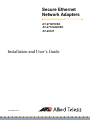
Secure Ethernet
Network Adapters
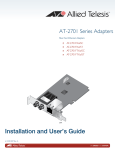
AT-2712FX/SC
AT-2712LX20/SC
AT-2912T
Installation and User’s Guide
613-001347 Rev. A
Copyright 2010 Allied Telesis, Inc.
All rights reserved. No part of this publication may be reproduced without prior written permission from Allied Telesis, Inc.
Allied Telesis and the Allied Telesis logo are trademarks of Allied Telesis, Incorporated. Broadcom® and the pulse logo are
among the trademarks of Broadcom Corporation. All other product names, company names, logos or other designations
mentioned herein are trademarks or registered trademarks of their respective owners.
Electrical Safety and Emissions Standards
This product meets the following standards.
U.S. Federal Communications Commission
Declaration of Conformity
Manufacturer Name: Allied Telesis, Inc.
Declares that the product: Secure Ethernet Adapter
Model Numbers: AT-2712FX/SC, AT-2712LX20/SC, and AT-2912T
This product complies with FCC Part 15B, Class B Limits:
This device complies with part 15 of the FCC Rules. Operation is subject to the following two conditions: (1) This device
must not cause harmful interference, and (2) this device must accept any interference received, including interference
that may cause undesired operation.
Radiated Energy
Note: This equipment has been tested and found to comply with the limits for a Class B digital device pursuant to Part 15
of FCC Rules. These limits are designed to provide reasonable protection against harmful interference in a residential
installation. This equipment generates, uses and can radiate radio frequency energy and, if not installed and used in
accordance with instructions, may cause harmful interference to radio or television reception, which can be determined
by turning the equipment off and on. The user is encouraged to try to correct the interference by one or more of the
following measures:
-
Reorient or relocate the receiving antenna.
-
Increase the separation between the equipment and the receiver.
-
Connect the equipment into an outlet on a circuit different from that to which the receiver is connected.
-
Consult the dealer or an experienced radio/TV technician for help.
Changes and modifications not expressly approved by the manufacturer or registrant of this equipment can void your
authority to operate this equipment under Federal Communications Commission rules.
Industry Canada
This Class B digital apparatus complies with Canadian ICES-003.
Cet appareil numérique de la classe B est conforme à la norme NMB-003 du Canada.
European Union Restriction of the Use of Certain Hazardous Substances
(RoHS) in Electrical and Electronic Equipment
This Allied Telesis RoHS-compliant product conforms to the European Union Restriction of the Use of Certain Hazardous
Substances (RoHS) in Electrical and Electronic Equipment. Allied Telesis ensures RoHS conformance by requiring
supplier Declarations of Conformity, monitoring incoming materials, and maintaining manufacturing process controls.
RFI Emissions
FCC Class B, EN55022 Class B, EN61000-3-2, EN61000-3-3, VCCI
Class B, C-TICK, CE
Immunity
EN55024
Electrical Safety
EN60950 (TUV), UL 60950 (CULUS)
Laser Safety
EN60825
3
Translated Safety Statements
Important: The indicates that a translation of the safety statement is available in a PDF
document titled “Translated Safety Statements” on the Allied Telesis website at
www.alliedtelesis.com/support/software. After you have accessed this website, enter the model
number in the Search by Product Name box and then click Find to view the current list of
documents.
4
Contents
Preface ................................................................................................................................................................................11
Safety Symbols Used in this Document................................................................................................................................12
Where to Find Management Software Updates and Product Information ............................................................................13
Contacting Allied Telesis ......................................................................................................................................................14
Online Support ..............................................................................................................................................................14
Email and Telephone Support .......................................................................................................................................14
Returning Products........................................................................................................................................................14
For Sales Information ....................................................................................................................................................14
Warranty ........................................................................................................................................................................14
Chapter 1: Introducing the Secure Ethernet Network Adapters ...................................................................................15
Functional Descriptions ........................................................................................................................................................16
AT-2712FX/SC and AT-2712LX20/SC Adapters...........................................................................................................16
AT-2912T Adapter .........................................................................................................................................................18
Supported Operating Systems and Features .......................................................................................................................19
Chapter 2: Installing the Hardware ..................................................................................................................................21
Reviewing Safety Precautions ..............................................................................................................................................22
Reviewing the Contents of Your Shipment ...........................................................................................................................24
Pre-Installation Checklist ......................................................................................................................................................25
Replacing the Bracket ..........................................................................................................................................................26
Replacing the Low-Profile Bracket ................................................................................................................................26
Replacing the Standard Bracket....................................................................................................................................28
Installing a Network Adapter Card ........................................................................................................................................29
Connecting the Network Cables ...........................................................................................................................................33
Chapter 3: Installing Windows Server 2003 and Windows XP Driver Software ...........................................................35
Installing the Driver Software................................................................................................................................................36
Using the Driver Installer ...............................................................................................................................................36
Updating the Adapter Software .....................................................................................................................................39
Modifying Configuration Properties ...............................................................................................................................43
Uninstalling the Driver Software ...........................................................................................................................................45
Chapter 4: Installing the Windows Vista and Windows 7 Driver Software ...................................................................47
Installing the Driver Software................................................................................................................................................48
Uninstalling the Driver Software ...........................................................................................................................................54
Chapter 5: Setting Advanced Properties .........................................................................................................................57
Accessing the Advanced Tab ...............................................................................................................................................58
Selecting the Advanced Tab in Windows Server 2003 or Windows XP ........................................................................58
Selecting the Advanced Tab in Windows 7 ...................................................................................................................61
Selecting the Advanced Tab in Windows Vista .............................................................................................................63
Modifying Advanced Properties ............................................................................................................................................65
Updating the Ethernet@WireSpeed Property ...............................................................................................................66
Updating the Flow Control Property ..............................................................................................................................66
Updating the Interrupt Moderation Property ..................................................................................................................68
Updating the Checksum Offload Property .....................................................................................................................69
Updating the Large Send Offload Property ...................................................................................................................70
Updating the Jumbo MTU Property ...............................................................................................................................71
Updating the Network Address Property .......................................................................................................................72
Updating the RSS Queues Property .............................................................................................................................73
Updating the Priority & VLAN Property..........................................................................................................................74
5
Contents
Updating the Receive Buffers Property .........................................................................................................................75
Updating the Receive Side Scaling Property.................................................................................................................75
Updating the Speed & Duplex Mode Property...............................................................................................................76
Updating the TCP Connection Offload Properties .........................................................................................................78
Updating the Transmit Buffers Property ........................................................................................................................79
Updating the VLAN ID Property.....................................................................................................................................79
Updating the WOL Speed..............................................................................................................................................80
Chapter 6: Enabling LINUX ...............................................................................................................................................81
Introduction ...........................................................................................................................................................................82
Limitations .....................................................................................................................................................................82
Packaging ......................................................................................................................................................................82
Installing LINUX TG3 File .....................................................................................................................................................83
Installing the Source RPM Package ..............................................................................................................................83
Building the Driver from the Source TAR File................................................................................................................84
Driver Settings ...............................................................................................................................................................85
Driver Default Settings...................................................................................................................................................86
Unloading and Removing the Driver .....................................................................................................................................88
Driver Messages ...................................................................................................................................................................89
Appendix A: Specifications ..............................................................................................................................................91
Physical Specifications .........................................................................................................................................................91
Environmental Specifications................................................................................................................................................91
Power Specifications.............................................................................................................................................................92
Performance Specifications ..................................................................................................................................................92
Quality and Reliability ...........................................................................................................................................................92
Operating Specifications .......................................................................................................................................................92
10/100/1000Base-T Twisted-Pair Port Connectors ..............................................................................................................93
Appendix B: Cleaning Fiber Optic Connectors ...............................................................................................................95
Using a Cartridge-Type Cleaner ...........................................................................................................................................96
Using a Swab........................................................................................................................................................................98
6
Figures
Figure 1. AT-2712FX/SC Adapter........................................................................................................................................16
Figure 2. AT-2712FX/SC Faceplate ....................................................................................................................................17
Figure 3. AT-2912T Adapter ................................................................................................................................................18
Figure 4. AT-2912T Faceplate.............................................................................................................................................18
Figure 5. Removing the Low-Profile Bracket .......................................................................................................................26
Figure 6. Fastening Screws onto Standard Bracket ............................................................................................................27
Figure 7. Removing the Standard Bracket...........................................................................................................................28
Figure 8. Fastening Screws onto Low-Profile Bracket.........................................................................................................28
Figure 9. Removing the PC Cover.......................................................................................................................................30
Figure 10. Removing the Faceplate From PCI Slot .............................................................................................................30
Figure 11. Inserting the Adapter with a High-profile Bracket ...............................................................................................31
Figure 12. Securing the Adapter with a High-profile Bracket...............................................................................................32
Figure 13. Welcome to the Found New Hardware Wizard Window.....................................................................................37
Figure 14. Found New Hardware Wizard Window: Search and Installation Options...........................................................38
Figure 15. Windows Server 2003 Start Window ..................................................................................................................40
Figure 16. Run Window .......................................................................................................................................................40
Figure 17. Device Manager Window (Network adapter folder is collapsed) ........................................................................41
Figure 18. Welcome to Hardware Update Wizard Window .................................................................................................42
Figure 19. Hardware Update Wizard Window .....................................................................................................................42
Figure 20. System Properties Dialog Box............................................................................................................................44
Figure 21. Windows 7 Search Box ......................................................................................................................................49
Figure 22. Windows Vista Start Menu .................................................................................................................................50
Figure 23. Windows Vista Run Window...............................................................................................................................50
Figure 24. Device Manager Window....................................................................................................................................51
Figure 25. Device Manager Window: Ethernet Controller ...................................................................................................52
Figure 26. Update Driver Software - Ethernet Controller Window .......................................................................................52
Figure 27. Update Driver Software: Ethernet Controller: Browse ........................................................................................53
Figure 28. Update Driver Software - Confirmation Window.................................................................................................53
Figure 29. System Properties Dialog Box............................................................................................................................59
Figure 30. Advanced Tab ....................................................................................................................................................60
Figure 31. Windows 7 Search Box ......................................................................................................................................61
Figure 32. Device Manager Window....................................................................................................................................62
Figure 33. Windows Vista Start Menu .................................................................................................................................63
Figure 34. Windows Vista Run Window...............................................................................................................................63
Figure 35. RJ-45 Connector and Port Pin Layout................................................................................................................93
Figure 36. Ferrule in an SC Connector Plug........................................................................................................................95
Figure 37. Unclean and Clean Ferrule.................................................................................................................................95
Figure 38. Cartridge Cleaner ...............................................................................................................................................96
Figure 39. Rubbing the Ferrule Tip on the Cleaning Surface ..............................................................................................96
Figure 40. Lint-Free and Alcohol-Free Swabs .....................................................................................................................98
Figure 41. Cleaning a Recessed Ferrule .............................................................................................................................98
7
Figures
8
Tables
Table 1: Safety Symbols ......................................................................................................................................................12
Table 2: Fiber Optic Port 100 LED Status ...........................................................................................................................17
Table 3: Twisted-Pair Port LED Status ................................................................................................................................18
Table 4: 1000BASE-SX Fiber Optic Cable Specifications ...................................................................................................33
Table 5: Ethtool Utility Examples .........................................................................................................................................86
Table 6: Linux Driver Settings ..............................................................................................................................................86
Table 7: MDI Pin Signals (10Base-T or 100Base-TX) .........................................................................................................93
Table 8: MDI-X Pin Signals (10Base-T or 100Base-TX) .....................................................................................................94
Table 9: RJ-45 1000Base-T Connector Pinouts ..................................................................................................................94
9
Tables
10
Preface
This guide contains instructions on how to install the AT-2712FX/SC,
AT-2712LX20/SC, and AT-2912T Secure Ethernet Network adapters and
configure the adapters using the driver software.
The Preface contains the following sections:
“Safety Symbols Used in this Document” on page 12
“Where to Find Management Software Updates and Product
Information” on page 13
“Contacting Allied Telesis” on page 14
11
Preface
Safety Symbols Used in this Document
This document uses the safety symbols defined in Table 1.
Table 1. Safety Symbols
Symbol
12
Meaning
Description
Caution
Performing or omitting a specific action may
result in equipment damage or loss of data.
Warning
Performing or omitting a specific action may
result in electrical shock.
Secure Ethernet Network Adapter Installation and User’s Guide
Where to Find Management Software Updates and Product
Information
New releases of management software are on the Allied Telesis web site.
In addition, the installation and user guides are available for all Allied
Telesis products in portable document format (PDF) on our web site. Both
the management software and the product documentation are available at
www.alliedtelesis.com/support/software/.
Once you access the web site, enter the hardware product model in the
Search by Product Name field. For example, enter “AT-2912T” and then
click Find. You can download the management software. In addition, you
can view the documents online or download them onto your local
workstation or server.
13
Preface
Contacting Allied Telesis
This section provides Allied Telesis contact information for technical
support as well as sales or corporate information.
Online Support
You can request technical support online by accessing the Allied Telesis
Knowledge Base: www.alliedtelesis.com/support/kb.aspx. You can use
the Knowledge Base to submit questions to our technical support staff and
review answers to previously asked questions.
Email and
Telephone
Support
For Technical Support via email or telephone, refer to the Support section
of the Allied Telesis web site: www.alliedtelesis.com/support.
Returning
Products
Products for return or repair must first be assigned a return materials
authorization (RMA) number. A product sent to Allied Telesis without an
RMA number will be returned to the sender at the sender’s expense. For
instructions on how to obtain an RMA number, go to the Support section
on our web site at www.alliedtelesis.com/support/rma.aspx.
For Sales
Information
Warranty
14
You can find the contact information for Allied Telesis sales offices or valued resellers listed on our web site at www.alliedtelesis.com/purchase.
To purchase Allied Telesis products directly, contact one of our sales representatives or one of our valued resellers.
Go to www.alliedtelesis.com/support/warranty for the specific terms
and conditions of the warranty and for warranty registration for the
AT-2712FX/SC, AT-2712LX20/SC, and AT-2912T adapters.
Chapter 1
Introducing the Secure Ethernet
Network Adapters
This chapter provides an introduction to the Allied Telesis AT-2712FX/SC,
AT-2712LX20/SC, and AT-2912T Secure Ethernet Network Adapters and
contains the following sections:
“Functional Descriptions” on page 16
“Supported Operating Systems and Features” on page 19
15
Chapter 1: Introducing the Secure Ethernet Network Adapters
Functional Descriptions
The AT-2712FX/SC, AT-2712LX20/SC, and AT-2912T adapters feature
in-built cryptographic processors that take over a number of data
encryption and decryption functions within the hardware, releasing the
host CPU to perform other tasks. This ensures the highest possible
speeds when transmitting or receiving secure data, without compromising
data security or host system performance.
As part of the company’s green range, all three adapters are engineered
to reduce power consumption. They incorporate centralized power
management features that automatically place idle circuitry into a lower
power mode to save energy and battery life in a laptop.
The following sections provide functional descriptions of the AT-2712FX/
SC, AT-2712LX/20SC, and AT-2912T adapters.
AT-2712FX/SC
and
AT-2712LX20/SC
Adapters
Both the AT-2712FX/SC and AT-2712LX20/SC adapters connect a PCIe
compliant server or workstation to a Fast Ethernet network using fiber
optic cabling and a connector. In addition, both adapters operate at
speeds of 100 Mbps in full-duplex and half-duplex modes. The two
adapters are identical in appearance. The AT-2712FX/SC adapter is
shown in Figure 1.
T
TX
RX
10
0
10
0
1478
Figure 1. AT-2712FX/SC Adapter
Both the AT-2712FX/SC and AT-2712LX20/SC adapters have one SC
connector. The AT-2712FX/SC adapter uses a connector that meets 62.5/
125 µm or 50/125 µm multimode specifications. AT-2712LX20/SC adapter
uses a connector that meets 9/125 µm single-mode specifications.
16
Secure Ethernet Network Adapter Installation and User’s Guide
The difference between the two adapters is their cable length
requirements. The AT-2712FX/SC is designed for multimode operation
using cables of up to in 275 meters (902 feet) in length. The AT-2712LX20/
SC adapter is designed for single mode operation using cables of up to 10
kilometers (6.123 miles) in length. For more information about the cables,
see Table 3 on page 33.
AT-2712FX/SC and AT-2712LX20/SC Adapters Physical Descriptions
The faceplate on the AT-2712FX/SC and AT-2712LX20/SC adapters
provides two fiber optic connectors for attaching the adapter to a
compatible link partner. See Figure 2 for an illustration of the adapter’s
faceplate.
Both the AT-2712FX/SC and AT-2712LX20/SC adapters have one fiber
port and one LED, as shown in Figure 2 and described in Table 1.
T
TX
RX
10
0
10
0
1484
Figure 2. AT-2712FX/SC Faceplate
Table 1. Fiber Optic Port 100 LED Status
State
Description
Green
The port is operating at 100 Mbps and has a valid
link.
Flashing
The port is receiving or transmitting network packets
at 100 Mbps.
17
Chapter 1: Introducing the Secure Ethernet Network Adapters
AT-2912T
Adapter
The AT-2912T adapter is a Gigabit Ethernet secure PCIe NIC featuring
on-board encryption. It is fully compatible with other secure IPSec as well
as non-IPSec NICs. This adapter operates at speeds of 10/100/1000T
Mbps in both full-duplex and half-duplex modes.
The AT-2912T adapter has one twisted-pair connector, as show in
Figure 3.
L/A
T
1594
Figure 3. AT-2912T Adapter
AT-2912T Adapter Physical Description
The faceplate on the AT-2912T adapter provides one twisted-pair
connector for attaching the adapter to a compatible link partner. See
Figure 4 for an illustration of the adapter’s faceplate.
L/A
T
1595
Figure 4. AT-2912T Faceplate
The AT-2912T adapter has one LED as described in Table 2.
Table 2. Twisted-Pair Port LED Status
State
18
Description
Green
The port is operating at 10/100/1000 Mbps and has
a valid link.
Flashing
The port is receiving or transmitting network packets
at 10/100/1000 Mbps
Secure Ethernet Network Adapter Installation and User’s Guide
Supported Operating Systems and Features
The Secure Ethernet Network adapters are shipped from the factory with
the default Broadcom software driver installed. You can download the
latest version of the software driver and our configuration from the Allied
Telesis website at www.alliedtelesis.com/support/software. After you
have accessed this website, enter the model number in the Search by
Product Name box and then click Find.
The Secure Ethernet Network adapters have software support for the
following operating systems:
Microsoft Windows Server 2003 (32-bit and 64-bit extended)
Microsoft Windows XP (32-bit and 64-bit extended)
Microsoft Windows Vista (32-bit and 64-bit extended)
Microsoft Windows 7 (32-bit and 64-bit extended)
Linux (32-bit and 64-bit extended)
The following list of features for the AT-2712FX/SC, AT-2712LX20/SC,
and AT-2912T adapters applies to all of the supported operating systems:
PCI Express x1 interface
Flow Control (IEEE 802.1x)
Layer 2 Priority Encoding (802.1p)
TCP checksum RX/TX support
72 KB packet buffer
PXE remote root support
Wake on LAN (WOL)
IPSec
19
Chapter 1: Introducing the Secure Ethernet Network Adapters
20
Chapter 2
Installing the Hardware
This chapter provides installation procedures for the adapters. It contains
the following sections:
“Reviewing Safety Precautions” on page 22
“Reviewing the Contents of Your Shipment” on page 24
“Pre-Installation Checklist” on page 25
“Replacing the Bracket” on page 26
“Installing a Network Adapter Card” on page 29
“Connecting the Network Cables” on page 33
21
Chapter 2: Installing the Hardware
Reviewing Safety Precautions
Please review the following safety precautions before you begin to install a
network adapter card.
Note
The indicates that a translation of the safety statement is
available in a PDF document titled “Translated Safety Statements”
on the Allied Telesis website at www.alliedtelesis.com/support/
software. After you have accessed this website, enter the model
number in the Search by Product Name box and then click Find to
view the current list of documents.
Warning
This is a “Class 1 LED product”. L1
Warning
Do not stare into the laser beam. L2
Warning
Warning: Do not look directly at the fiber optic cable ends or inspect
the cable ends with an optical lens. E29
Warning
Do not work on this equipment or cables during periods of lightning
activity. E2
Warning
Operating Temperature: This product is designed for a maximum
ambient temperature of 40 degrees C. E7
Note
All Countries: Install this product in accordance with local and
National Electric Codes. E8
Warning
The adapter is being installed in a system that operates with
voltages that can be lethal. Before you remove the cover of your
system, you must observe the following precautions to protect
yourself and to prevent damage to the system components.
22
Secure Ethernet Network Adapter Installation and User’s Guide
- Remove any metallic objects or jewelry from your hands and
wrists.
- Make sure to use only insulated or nonconducting tools.
- Verify that the system is powered OFF and unplugged before
accessing internal components.
- Installation or removal of adapters must be performed in a staticfree environment. The use of a properly grounded wrist strap or
other personal antistatic devices and an antistatic mat is strongly
recommended. E39
23
Chapter 2: Installing the Hardware
Reviewing the Contents of Your Shipment
The following items are included with your adapter:
Antistatic bag (used for protecting the adapter when stored or
shipped). Keep the adapter in its packaging until ready for installation.
Low-profile bracket (attached to the AT-2712FX/SC and
AT-2712LX20/SC adapters)
Standard bracket (attached to the AT-2912T adapter)
Inform your network supplier of any missing or damaged items. If you
need to return the adapter, you must pack it in the original (or equivalent)
packing material or the warranty will be voided. See “Returning Products”
on page 14.
The installation and user guides for all Allied Telesis products are
available in PDF format on our web site at www.alliedtelesis.com/
support/software. For further instructions, see “Where to Find
Management Software Updates and Product Information” on page 13.
24
Secure Ethernet Network Adapter Installation and User’s Guide
Pre-Installation Checklist
Before you install an adapter card, check the following list:
1. Verify that your system is using the latest BIOS.
Note
If you acquired the adapter software from the Allied Telesis support
website, download the software drivers and then enter the path to
where the adapter driver files reside on your system. For instructions
that describe how to download the software, see “Where to Find
Management Software Updates and Product Information” on
page 13.
2. If your system is active, shut it down.
3. When the system shut down is complete, power OFF and unplug your
system.
4. Holding the adapter card by the edges, remove it from its shipping
package and place it on an antistatic surface.
5. Check the adapter for visible signs of damage, particularly on the
card’s edge connector.
Caution
Do not attempt to install a damaged adapter. If the adapter is
damaged, report it to Allied Telesis. See “Contacting Allied Telesis”
on page 14.
25
Chapter 2: Installing the Hardware
Replacing the Bracket
Depending on your PC, you may need to replace the bracket attached to
your adapter. The AT-2712FX/SC and AT-2712LX20/SC adapters are
shipped with the low-profile bracket attached to the adapter. The AT2912T adapter is shipped with the standard bracket attached to the
adapter.
The following procedures describe how to replace a bracket:
“Replacing the Low-Profile Bracket” on page 26
“Replacing the Standard Bracket” on page 28
In both procedures, the AT-2712FX/SC adapter is shown in the
illustrations. However, you can perform the procedures on all three
adapters.
Replacing the
Low-Profile
Bracket
To replace the low-profile bracket with the standard bracket, perform the
following procedure:
1. Remove the screws that attach the bracket to the adapter. See
Figure 5.
TX
RX
10
0
1479
Figure 5. Removing the Low-Profile Bracket
26
Secure Ethernet Network Adapter Installation and User’s Guide
2. Align the tabs of the standard bracket with the holes on the adapter
and fasten the screws onto the adapter. See Figure 6.
TX
RX
10
0
1480
Figure 6. Fastening Screws onto Standard Bracket
27
Chapter 2: Installing the Hardware
Replacing the
Standard Bracket
To replace the standard bracket with the low-profile bracket, perform the
following procedure:
1. Remove the screws that attach the bracket to the adapter. See
Figure 7.
TX
RX
10
0
1888
Figure 7. Removing the Standard Bracket
2. Align the tabs of the low-profile bracket with the holes on the adapter
and fasten the screws onto the adapter. See Figure 8.
TX
RX
10
0
1889
Figure 8. Fastening Screws onto Low-Profile Bracket
28
Secure Ethernet Network Adapter Installation and User’s Guide
Installing a Network Adapter Card
The following instructions apply to installing the AT-2712FX/SC, AT2712LX20/SC, and AT-2912T adapters in most systems. For details about
performing these tasks on your particular system, refer to the manuals that
were supplied with your system.
Note
To perform this procedure, you need to provide one Phillips-head
screw.
To install an adapter, perform the following procedure:
1. Review the “Pre-Installation Checklist” on page 25 and “Reviewing
Safety Precautions” on page 22.
Before installing the adapter, ensure the system power is OFF and
unplugged from the power outlet, and that proper electrical grounding
procedures have been followed.
Warning
High voltage inside the system presents a safety hazard. Make sure
the power is off before removing the cover.
2. Remove the system cover and select any appropriate empty PCI slot.
See Figure 9 on page 30.
If you do not know how to identify an appropriate PCI slot, refer to your
system documentation.
29
Chapter 2: Installing the Hardware
Figure 9. Removing the PC Cover
3. Select an empty, non-shared PCI slot and remove the faceplate.
Keep the faceplate in a safe place. You may need it for future use. See
Figure 10.
Figure 10. Removing the Faceplate From PCI Slot
Note
If you cannot locate or do not know how to find an appropriate PCI
slot, refer to the documentation that came with your system.
30
Secure Ethernet Network Adapter Installation and User’s Guide
4. Remove the network adapter card from the shipping package and
store the packaging material in a safe location.
Caution
Wear a grounding device and observe electrostatic discharge
precautions when installing the network adapter card in a system.
Failure to observe this caution could result in damage to the card.
5. Applying even pressure at both corners of the card, push the adapter
card until it is firmly seated in the appropriate PCI slot.
Make sure the card is securely seated. To insert the network adapter
card, see Figure 11.
Figure 11. Inserting the Adapter with a High-profile Bracket
Caution
Do not use excessive force when seating the card, because this may
damage the system or the adapter. If the card resists seating,
remove it from the system, realign it, and try again.
6. Secure the network adapter card to the chassis with a Phillips-head
screw (not provided). See Figure 12 on page 32.
31
Chapter 2: Installing the Hardware
Figure 12. Securing the Adapter with a High-profile Bracket
7. Replace the system’s cover and secure it with the screws removed in
Step 2.
8. Disconnect any personal antistatic devices.
9. Power the system on.
Once the system returns to proper operation, the adapter hardware is
fully installed. Next, connect the network cables. See “Connecting the
Network Cables” on page 33.
32
Secure Ethernet Network Adapter Installation and User’s Guide
Connecting the Network Cables
The AT-2712FX/SC and AT-2712LX20/SC adapters have two fiber optic
connectors (transmit and receive) for attaching the system to a compatible
link partner or an IEEE 802.3z compliant Fast Ethernet switch. Both
adapters require a fiber optic cable.
The AT-2912T adapter has one twisted-pair connector which requires a
twisted-pair cable. For pin signals and pinout information, see “10/100/
1000Base-T Twisted-Pair Port Connectors” on page 93.
To connect a network cable to the adapter, perform the following
procedure:
Warning
The fiber optic ports contain a Class 1 LED device. When the ports
are disconnected, always cover them with the provided plug.
Exposed ports may cause skin or eye damage.
1. Connect one end of the cable to the adapter:
For the AT-2912T adapter, connect one end of the twisted-pair
cable to the adapter.
For the AT-2712FX/SC and AT-2712LX20/SC adapters, prepare a
fiber optic cable according to the specifications in Table 3. Connect
one end of the cable to the adapter.
Table 3. 1000BASE-SX Fiber Optic Cable Specifications
Media
Maximum
Distance
Port Type
Connector
Wavelength
1000BASE-SX
Fiber Optic
62.5 µm multimode
850 nm
275 meters
(853 feet)
1310 nm
1000BASE-LX
Fiber Optic
9.125 µm single mode
1310 nm
10 kilometer
(6.213 miles)
1310 nm
2. Connect the other end of the cable:
For the AT-2912T adapter, connect the other end of the cable to
another twisted pair port.
For the AT-2712FX/SC and AT-2712LX20/SC adapters, connect
the other end of the cable to the appropriate Ethernet fiber optic
port.
33
Chapter 2: Installing the Hardware
Note
After the cable is properly connected at both ends, the adapter port
LEDs is functional. For descriptions of LED operation, see “AT2712FX/SC and AT-2712LX20/SC Adapters Physical Descriptions”
on page 17 or “AT-2912T Adapter Physical Description” on page 18.
After you connect the system to the network and power is supplied, the
AT-2712FX/SC and AT-2712LX20/SC adapters attempt to establish
the connection at 100 Mbps full-duplex. The AT-2912T uses
Autonegotiation to determine the connection settings.
34
Chapter 3
Installing Windows Server 2003 and
Windows XP Driver Software
This chapter describes how to install the Windows Server 2003 and
Windows XP driver software. This chapter contains the following sections:
“Installing the Driver Software” on page 36
“Uninstalling the Driver Software” on page 45
After you install the driver software, you can modify the configuration
properties as described in see Chapter 5, “Setting Advanced Properties”
on page 57.
35
Chapter 3: Installing Windows Server 2003 and Windows XP Driver Software
Installing the Driver Software
When a Windows Server 2003 or Windows XP system first boots up after
installing a new Secure Ethernet Network adapter, the system
automatically detects the new hardware and prompts you to install the
driver software for that device.
There are three installation procedures:
“Using the Driver Installer” on page 36
“Updating the Adapter Software” on page 39
“Modifying Configuration Properties” on page 43
Note
The adapter must be physically installed in your system before
installing the driver software. See Chapter 2, “Installing the
Hardware” on page 21 for details.
Note
If the Windows Server 2003 or Windows XP system detects an
adapter and installs a default driver, update the driver as described
in “Updating the Adapter Software” on page 39.
Note
If there is an onboard Broadcom network interface, the native
Broadcom driver may load. You can use this driver, or the latest
driver supplied by Allied Telesis.
Using the Driver
Installer
When you boot up either operating system after installing the adapter
card, a series of Found New Hardware windows are displayed. You must
have Administrator privileges to install the driver software.
Note
Before beginning this procedure, verify that the Windows Server
2003 or Windows XP system has been upgraded to the latest
version with the latest service pack applied.
Note
If you have a Windows XP system, the window in Figure 13 on page
37 opens. Start with step 1. If you have a Windows Server 2003
system, the window in Figure 14 on page 38 opens. Start with step 3
on the same page.
36
Secure Ethernet Network Adapters Installation and User’s Guide
To install the adapter software on a Windows Server 2003 or Windows XP
system, do the following:
1. Click Install from a list or specific location (Advanced).
Figure 13. Welcome to the Found New Hardware Wizard Window
2. Click Next.
The second Welcome to the Found New Hardware Wizard Window is
shown in Figure 14 on page 38.
37
Chapter 3: Installing Windows Server 2003 and Windows XP Driver Software
Figure 14. Found New Hardware Wizard Window: Search and Installation
Options
3. Click Include this location in the search.
4. Click Browse and locate the path of the software driver.
5. Click Next.
6. When the software installation is complete, click Finish to close the
wizard and complete the software installation.
38
Secure Ethernet Network Adapters Installation and User’s Guide
Updating the
Adapter Software
This section provides a procedure for updating the adapter software for the
Windows Server 2003 or Windows XP systems. To obtain the latest
version of an Secure Ethernet Network adapter software drivers, download
it from the Allied Telesis website. For instructions, see “Where to Find
Management Software Updates and Product Information” on page 13.
Note
You may need to reboot your system after completing the driver
update to properly load the new drivers.
When you update the adapter software on existing devices, the Advanced
Property settings may not be updated unless you remove the existing
device by following the instructions in “Uninstalling the Driver Software” on
page 45. Then perform a scan for hardware changes in the device
manager followed by reinstalling the device with the current adapter
software as described in “Installing the Driver Software” on page 36.
Note
Before uninstalling a device, capture all of the Advanced Property
settings because the properties will be lost.
Updating the Windows Server 2003 or Windows XP Driver Software
To update the adapter software on a Windows Server 2003 or a Windows
XP system, perform the following procedure.
Note
Update all adapters by repeating the following steps on each device.
1. Start either a Windows Server 2003 or a Windows XP system and
log in.
You must have Administrator privileges to update the driver software.
2. On the desktop, open the Start menu.
See Figure 15 on page 40 for an example of the Start menu.
39
Chapter 3: Installing Windows Server 2003 and Windows XP Driver Software
Figure 15. Windows Server 2003 Start Window
3. Select Run from the menu and enter the following command:
devmgmt.msc
See Figure 16 for an example of the Run Window.
Figure 16. Run Window
40
Secure Ethernet Network Adapters Installation and User’s Guide
The Device Manager Window is shown in Figure 17.
Figure 17. Device Manager Window (Network adapter folder is collapsed)
4. In the Device Manager window, click the + next to the Network
adapters folder.
The selection expands to show the list of installed network adapter
cards.
5. Right click on one of the following the adapters:
Allied Telesis AT-2712FX/SC
Allied Telesis AT-2912T
Note
Select “AT-2712FX/SC” to update the drivers for either the AT2712FX/SC or the AT-2712LX20/SC adapter.
6. Select Update Driver.
41
Chapter 3: Installing Windows Server 2003 and Windows XP Driver Software
The Hardware Update Wizard Window opens, as shown in Figure 18.
Figure 18. Welcome to Hardware Update Wizard Window
7. For a Windows Server 2003 system, skip to step 10. For a Windows
XP system, click No, not this time to copy the driver software from
your PC.
8. Click Next.
The Second New Found Hardware Wizard Window opens, as shown
in Figure 19.
Figure 19. Hardware Update Wizard Window
42
Secure Ethernet Network Adapters Installation and User’s Guide
9. Click Install from a list or specified location (Advanced).
10. Click Next.
11. If you are prompted to specify the location of the software driver, click
Browse (do not use the text field) and locate the path.
After you install the driver software, you can modify the configuration
properties. See Chapter 5, “Setting Advanced Properties” on page 57.
Modifying
Configuration
Properties
Although the default values are appropriate in most cases, you can
change any of the available options to meet the requirements of your
specific system. After the adapter driver software has been installed, you
can use this procedure to access the System Property Dialog box which
provides access to the Advanced Properties on the Advanced Tab.
To access the System Properties Dialog box, perform the following
procedure:
1. Start either a Windows Server 2003 or a Windows XP system and
log in.
You must have Administrator privileges to update the driver software.
2. On the desktop, right click My Computer.
The My Computer window opens.
3. Select Properties from the menu.
The System Properties Dialog box opens, as shown in Figure 20 on
page 44.
43
Chapter 3: Installing Windows Server 2003 and Windows XP Driver Software
Figure 20. System Properties Dialog Box
For instructions that describe how to set the Advanced Properties, see
Chapter 5, “Setting Advanced Properties” on page 57.
44
Secure Ethernet Network Adapters Installation and User’s Guide
Uninstalling the Driver Software
Before physically removing an adapter from your system, you must
uninstall the adapter driver software.
Caution
Before uninstalling the Allied Telesis device, be sure to capture all
Advanced Property settings because the properties are lost during
the uninstall process.
To uninstall the adapter software from your system, perform the following
procedure:
1. Start Windows Server 2003 or Windows XP and log in.
Note
You must have Administrator privileges to remove the driver
software.
2. Choose from the following:
If you have a Windows Server 2003 Server system, click Start.
Then select the Control Panel from the menu. Double-click the
System icon.
If you have a Windows XP system, right click on My Computer
Then select Properties from the menu.
The Device Manager Window opens. It is shown in Figure 17 on page
41.
3. In the Device Manager window, click the + next to the Network
adapters folder.
The selection expands to show the list of installed network adapter
cards.
4. Right-click on the adapter to be removed. Select from the following:
Allied Telesis AT-2712FX/SC
Allied Telesis AT-2912T
Note
Select “AT-2712FX/SC” to update the drivers for either the AT2712FX/SC or the AT-2712LX20/SC adapter.
45
Chapter 3: Installing Windows Server 2003 and Windows XP Driver Software
5. Select Uninstall.
A Confirm Device Removal window opens.
6. Click OK to complete the uninstall.
Note
Not all driver files are removed as part of this procedure.
46
Chapter 4
Installing the Windows Vista and Windows 7
Driver Software
This chapter describes how to install the Windows Vista and Windows 7
driver software on a Secure Ethernet Network adapter. The installation
procedures are identical for both the 32-bit and 64-bit Windows Operating
systems.
This chapter contains the following sections:
“Installing the Driver Software” on page 48
“Uninstalling the Driver Software” on page 54
Note
To set Advanced Properties, see Chapter 5, “Setting Advanced
Properties” on page 57.
47
Chapter 4: Installing the Windows Vista and Windows 7 Driver Software
Installing the Driver Software
After you install a Secure Ethernet Network adapter, the system detects
the new hardware and creates an entry in the Device Manager when the
Windows operating system first boots up. Shortly after you log in, you
need to install the driver software for the Secure Ethernet Network
adapter. To install or update the driver software, you must have
administrative privileges.
To obtain the latest Secure Ethernet Network adapter software drivers, go
to the Allied Telesis website at www.alliedtelesis.com/support/
software. For further instructions, see “Where to Find Management
Software Updates and Product Information” on page 13.
To install the Windows Vista or Windows 7 Operating System driver
software, do the following:
Note
The adapter must be physically installed in your system before you
install the driver software. See Chapter 2, “Installing the Hardware”
on page 21 for instructions.
1. Start a Windows operating system and log in.
2. Open the Device Manager.
For instructions on how to open the Device Manager, see one of the
following procedures:
48
–
To open the Device Manager in the Windows 7
Operating System, follow steps 3 and 4.
–
To open the Device Manager in the Windows Vista
Operating System, follow steps 5 through 7.
Secure Ethernet Network Adapter Installation and User’s Guide
3. To select the Device Manager in the Windows 7 Operating System,
select the Start button. The Windows 7 Search Box is displayed. See
Figure 21.
Figure 21. Windows 7 Search Box
4. Enter the following command:
mmc compmgmt.msc
The Device Manager window is displayed. For an example of the
Device Manager window, see Figure 24 on page 51.
5. To select the Device Manager in the Windows Vista Operating System,
select the Start menu.
49
Chapter 4: Installing the Windows Vista and Windows 7 Driver Software
See Figure 22 for an example of the Windows Vista Start menu.
Figure 22. Windows Vista Start Menu
6. From the Start Menu, select Run.
The Windows Vista Run window is displayed. See Figure 23.
Figure 23. Windows Vista Run Window
7. Enter the following command in the Run window:
mmc devmgmt.msc
50
Secure Ethernet Network Adapter Installation and User’s Guide
Figure 24. Device Manager Window
8. Open the Network Adapters folder.
The list of installed adapters is displayed.
9. Right click on the Secure Network Ethernet adapter.
The adapter window is displayed.
10. In the Device Manager window, click the + next to the Network
adapters folder.
The selection expands to show the list of installed network adapter
cards installed on your PC.
11. Right click on one of the following adapters:
Allied Telesis AT-2712FX/SC
Allied Telesis AT-2912T
Note
Select “AT-2712FX/SC” to update the software drivers on either the
AT-2712FX/SC adapter or the AT-2712LX20/SC adapter.
51
Chapter 4: Installing the Windows Vista and Windows 7 Driver Software
12. Right click Ethernet Controller and select Update Driver Software.
See Figure 25 for an example of the Device Manger window with
Ethernet Controller selected.
Figure 25. Device Manager Window: Ethernet Controller
13. Select Update Driver Software.
The Update Driver Software - Ethernet Controller Window is displayed.
See Figure 26.
Figure 26. Update Driver Software - Ethernet Controller Window
14. Click Browse my computer for driver software.
The Update Driver Software - Ethernet Controller: Browse for Driver
Software Window is displayed. See Figure 27 on page 53.
52
Secure Ethernet Network Adapter Installation and User’s Guide
15. Click Browse to search your computer for the location of the driver
software. See Figure 27.
Figure 27. Update Driver Software: Ethernet Controller: Browse
16. Click Next. A confirmation message is displayed. See Figure 28.
Figure 28. Update Driver Software - Confirmation Window
53
Chapter 4: Installing the Windows Vista and Windows 7 Driver Software
Uninstalling the Driver Software
Before physically removing an adapter from your system, you need to
uninstall the driver software first. The procedure in this section describes
how to uninstall the driver software.
Note
You must have Administrator privileges to remove the driver
software.
Caution
Before uninstalling the Allied Telesis device, be sure to capture all of
the Advanced Property settings because the properties are lost
during the uninstall process.
To uninstall the driver software from your system, do the following:
1. Start a Windows Vista or Windows 7 Operating System on your laptop
and log in.
2. Open the Device Manager.
For instructions on how to open the Device Manager, see the
following:
3. Open the Device Manager:
To open the Device Manager in the Windows 7 Operating System,
follow steps 3 and 4.
To open the Device Manager in the Windows Vista Operating
System, follow steps 5 through 7.
4. To select the Device Manager in the Windows 7 Operating System,
select the Start button. See Figure 21 on page 49.
5. Enter the following command:
mmc compmgmt.msc
The Device Manager window is displayed. For an example of the
Device Manager window, see Figure 24 on page 51.
6. To select the Device Manager in the Windows Vista Operating
System, select the Start menu.
The Windows 7 Search Box is displayed. See Figure 22 on page 50.
54
Secure Ethernet Network Adapter Installation and User’s Guide
7. From the Start Menu, select Run.
The Windows Vista Run window is displayed. See Figure 23 on page
50.
8. Enter the following command in the Run window:
mmc devmgmt.msc
The Device Manager Window is shown in Figure 24 on page 51.
9. In the Device Manager window, click the + next to the Network
adapters folder.
The selection expands to show the list of installed network adapter
cards.
10. Right click on one of the following adapters:
Allied Telesis AT-2712FX/SC
Allied Telesis AT-2912T
Note
Select “AT-2712FX/SC” to remove the software drivers on either the
AT-2712FX/SC adapter or the AT-2712LX20/SC adapter.
The adapter window is displayed.
11. Select Uninstall.
A Confirm Device Removal window opens.
12. Click OK to complete the uninstall.
Note
Not all of the driver files are removed as a result of this procedure.
You can remove additional drivers and installation files by selecting
the checkbox to remove these files.
55
Chapter 4: Installing the Windows Vista and Windows 7 Driver Software
56
Chapter 5
Setting Advanced Properties
For all of the Windows operating systems, you access the Windows
Advanced Properties from the Advanced Tab. Although the default values
of the Advanced Properties are appropriate in most cases, you can change
any of the available options to meet the requirements of your system.
This chapter discusses the following topics:
“Accessing the Advanced Tab” on page 58
“Modifying Advanced Properties” on page 65
57
Chapter 5: Setting Advanced Properties
Accessing the Advanced Tab
To modify the configuration properties of the Windows Operating systems,
you must access the Advanced Tab. Depending on your operating
system, there are several ways to do this. See the following procedures:
Selecting the
Advanced Tab
in Windows
Server 2003 or
Windows XP
“Selecting the Advanced Tab in Windows Server 2003 or Windows
XP” on page 58
“Selecting the Advanced Tab in Windows 7” on page 61
“Selecting the Advanced Tab in Windows Vista” on page 63
After you have installed the adapter driver software, you can use this
procedure to access the System Property Dialog box which provides
access to the Advanced Properties on the Advanced Tab.
To access the System Properties Dialog box, do the following:
1. Start a Windows Server 2003 or Windows XP system and log in.
You must have Administrator privileges to update the driver software.
2. On the desktop, right click My Computer.
The My Computer window opens.
3. Select Properties from the menu.
The System Properties Dialog box opens, as shown in Figure 29 on
page 59.
58
Secure Ethernet Network Adapters Installation and User’s Guide
Figure 29. System Properties Dialog Box
4. Click on the Advanced tab on the System Properties Dialog Box which
is located at the top of the window.
59
Chapter 5: Setting Advanced Properties
The Advanced tab is shown in Figure 30.
Figure 30. Advanced Tab
60
Secure Ethernet Network Adapters Installation and User’s Guide
Selecting the
Advanced Tab in
Windows 7
To select the Advanced Tab in Windows 7 Operating systems, do the
following:
1. Select the Start button. See Figure 31.
Figure 31. Windows 7 Search Box
2. Enter the following command:
mmc compmgmt.msc
The Device Manager window is displayed. See Figure 32 on page 62.
61
Chapter 5: Setting Advanced Properties
Figure 32. Device Manager Window
3. Open the Network Adapters folder.
The list of installed adapters is displayed.
4. Right click on one of the following adapters:
Allied Telesis AT-2712FX/SC
Allied Telesis AT-2912T
Note
Select “AT-2712FX/SC” to indicate either the AT-2712FX/SC
adapter or the AT-2712LX20/SC adapter.
The adapter window is displayed.
5. Select the Advanced tab.
The Advanced tab is shown in Figure 30 on page 60.
62
Secure Ethernet Network Adapters Installation and User’s Guide
Selecting the
Advanced Tab in
Windows Vista
In the Windows Vista Operating System, you access the Advanced Tab
through the Device Manager.
To select the Device Manager in the Windows Vista Operating System, do
the following:
1. Select the Start menu.
See Figure 33 for an example of the Windows Vista Start menu.
Figure 33. Windows Vista Start Menu
2. From the Start Menu, select Run.
The Windows Vista Run window is displayed. See Figure 34.
Figure 34. Windows Vista Run Window
63
Chapter 5: Setting Advanced Properties
3. Enter the following command in the Run window:
mmc devmgmt.msc
4. From the Computer Management Window, select Device Manager in
the left panel.
The Device Manager window is displayed. See Figure 32 on page 62.
5. Open the Network Adapters folder.
The list of installed adapters is displayed.
6. Right click on one of the following adapters:
Allied Telesis AT-2712FX/SC
Allied Telesis AT-2912T
Note
Select “AT-2712FX/SC” to indicate either the AT-2712FX/SC
adapter or the AT-2712LX20/SC adapter.
The adapter window is displayed.
7. Select the Advanced tab.
The Advanced tab is shown in Figure 30 on page 60.
64
Secure Ethernet Network Adapters Installation and User’s Guide
Modifying Advanced Properties
After you have installed the driver software, you can use the following
procedures to verify or change the adapter properties:
“Updating the Ethernet@ WireSpeed Property” on page 66
“Updating the Flow Control Property” on page 66
“Updating the Interrupt Moderation Property” on page 68
“Updating the Checksum Offload Property” on page 69
“Updating the Large Send Offload Property” on page 70
“Updating the Jumbo MTU Property” on page 71
“Updating the Network Address Property” on page 72
“Updating the RSS Queues Property” on page 73
“Updating the Priority & VLAN Property” on page 74
“Updating the Receive Buffers Property” on page 75
“Updating the Receive Side Scaling Property” on page 75
“Updating the Speed & Duplex Mode Property” on page 76
“Updating the TCP Connection Offload Properties” on page 78
“Updating the Transmit Buffers Property” on page 79
“Updating the VLAN ID Property” on page 79
“Updating the WOL Speed” on page 80
Note
After you upgrade the driver software, the Advanced Properties may
change.
Note
The procedures in the sections listed above may differ slightly if the
“Classic Start Menu” is set on your computer.
65
Chapter 5: Setting Advanced Properties
Updating the
Ethernet@
WireSpeed
Property
The Ethernet@Wirespeed property enables a Secure Ethernet Network
adapter to establish a link at a lower speed when only two pairs of wires
are available in the cabling plant. By default, the Ethernet@Wirespeed
property is enabled.
To enable or disable the Ethernet@WireSpeed property, do the following:
1. Access the Advanced tab:
For Windows Server 2003 Operating systems, see “Selecting the
Advanced Tab in Windows Server 2003 or Windows XP” on
page 58.
For Windows 7 Operating systems, see “Selecting the Advanced
Tab in Windows 7” on page 61.
For Windows Vista Operating systems, see “Selecting the
Advanced Tab in Windows Vista” on page 63.
The Advanced tab is shown in Figure 30 on page 60.
2. From the Property list on the Advanced tab, select
Ethernet@Wirespeed.
3. From the Value list on the Advanced tab, select one of the following:
Enable - Enables Ethernet@Wirespeed. This is the default.
Disable - Disables Ethernet@Wirespeed.
4. Click OK.
5. If you are prompted to restart your computer, click Yes.
Although it is not necessary to reboot the system for new adapter
properties to take effect, Allied Telesis recommends rebooting
recommended to reinitialize all of the registers.
6. Verify that the adapter port LEDs are operating correctly. See one of
the following descriptions:
Updating the
Flow Control
Property
66
“AT-2712FX/SC and AT-2712LX20/SC Adapters Physical
Descriptions” on page 17
“AT-2912T Adapter Physical Description” on page 18
The Flow Control property allows you to enable or disable the receipt or
transmission of PAUSE frames which, in turn, allows the adapter and the
switch to control the transmit rate. The port side that receives the PAUSE
frame momentarily stops transmitting. The recommended selection is
Disable, which configures the adapter to ignore PAUSE frames. By
default, the Flow Control property is disabled.
Secure Ethernet Network Adapters Installation and User’s Guide
To change the Flow Control property, do the following:
1. Access the Advanced tab:
For Windows Server 2003 Operating systems, see “Selecting the
Advanced Tab in Windows Server 2003 or Windows XP” on
page 58.
For Windows 7 Operating systems, see “Selecting the Advanced
Tab in Windows 7” on page 61.
For Windows Vista Operating systems, see “Selecting the
Advanced Tab in Windows Vista” on page 63.
The Advanced tab is shown in Figure 30 on page 60.
2. From the Property list on the Advanced tab, select Flow Control.
3. From the Value list on the Advanced tab, select one of the following:
Auto - (default) PAUSE frame receipt and transmission is
optimized.
Disable - PAUSE frame receipt and transmission is disabled
(recommended).
Rx PAUSE - PAUSE frame receipt is enabled.
Rx/Tx PAUSE - PAUSE frame receipt and transmission is
enabled.
Tx PAUSE - PAUSE frame transmission is enabled.
4. Click OK.
5. If prompted to restart your computer, click Yes.
Although it is not necessary to reboot the system for new adapter
properties to take effect, rebooting is recommended to reinitialize all of
the registers.
6. Verify that the port LED operates correctly. See one of the following
descriptions:
“AT-2712FX/SC and AT-2712LX20/SC Adapters Physical
Descriptions” on page 17
“AT-2912T Adapter Physical Description” on page 18
67
Chapter 5: Setting Advanced Properties
Updating the
Interrupt
Moderation
Property
Interrupt moderation enables adaptive interrupt coalescing, which limits
the rate of interrupt to the CPU during packet transmission and packet
reception. The disabled option allows one interrupt for every packet
transmission and packet reception. The default value is Enabled.
To change the Interrupt Moderation setting, do the following:
1. Access the Advanced tab:
For Windows Server 2003 Operating systems, see “Selecting the
Advanced Tab in Windows Server 2003 or Windows XP” on
page 58.
For Windows 7 Operating systems, see “Selecting the Advanced
Tab in Windows 7” on page 61.
For Windows Vista Operating systems, see “Selecting the
Advanced Tab in Windows Vista” on page 63.
The Advanced tab is shown in Figure 30 on page 60.
2. From the Property list on the Advanced tab, select Interrupt
Moderation.
For an example of the Advanced tab, see Figure 30 on page 60.
3. From the Value list on the Advanced tab, select one of the following:
Enabled
Disabled
4. Click OK.
5. If prompted to restart your computer, click Yes.
Although it is not necessary to reboot the system for new adapter
properties to take effect, Allied Telesis recommends rebooting to
reinitialize all of the registers.
6. Verify that the port LED operates correctly. See one of the following
descriptions:
68
“AT-2712FX/SC and AT-2712LX20/SC Adapters Physical
Descriptions” on page 17
“AT-2912T Adapter Physical Description” on page 18
Secure Ethernet Network Adapters Installation and User’s Guide
Updating the
Checksum
Offload Property
Usually, the Checksum Offload function is computed by the protocol stack.
By selecting one of the Checksum Offload properties, the adapter can
compute the checksum.
To change the Checksum Offload setting, do the following:
1. Access the Advanced tab:
For Windows Server 2003 Operating systems, see “Selecting the
Advanced Tab in Windows Server 2003 or Windows XP” on
page 58.
For Windows 7 Operating systems, see “Selecting the Advanced
Tab in Windows 7” on page 61.
For Windows Vista Operating systems, see “Selecting the
Advanced Tab in Windows Vista” on page 63.
The Advanced tab is shown in Figure 30 on page 60.
2. From the Property list under the Advanced tab, select IPv4 Checksum
Offload or IPv6 Checksum Offload.
3. From the Value list on the Advanced tab, select one of the following:
None - Disables checksum offloading.
Rx TCP/IP Checksum - Enables receive TCP, IP, and UDP
checksum offloading.
Tx TCP/IP Checksum - Enables transmit TCP, IP, and UDP
checksum offloading.
Tx/Rx TCP/IP Checksum (default) - Enables transmit and receive
TCP, IP, and UDP checksum offloading.
4. Click OK.
5. If prompted to restart your computer, click Yes.
Although it is not necessary to reboot the system for new adapter
properties to take effect, rebooting is recommended to reinitialize all
registers.
6. Verify that the port LED operates correctly. See one of the following
descriptions:
“AT-2712FX/SC and AT-2712LX20/SC Adapters Physical
Descriptions” on page 17
“AT-2912T Adapter Physical Description” on page 18
69
Chapter 5: Setting Advanced Properties
Updating the
Large Send
Offload Property
Normally, the protocol stack performs TCP segmentation. When you
enable the Large Send Offload property, the network adapter does the
TCP segmentation. There are several Large Send Offload properties to
choose from, depending on the TCP/IP version you are using on your PC.
You can select IPV4, IPV4 version 2, or IPv6 version 2. By default, the
Large Send Offload Property is disabled.
To change the Large Send Offload property, do the following:
1. Access the Advanced tab:
For Windows Server 2003 Operating systems, see “Selecting the
Advanced Tab in Windows Server 2003 or Windows XP” on
page 58.
For Windows 7 Operating systems, see “Selecting the Advanced
Tab in Windows 7” on page 61.
For Windows Vista Operating systems, see “Selecting the
Advanced Tab in Windows Vista” on page 63.
The Advanced tab is shown in Figure 30 on page 60.
2. From the Property list on the Advanced tab, select one of the following:
IPv4 Large Send Offload
IPv6 Large Send Offload
3. From the Value list on the Advanced tab, select one of the following:
Enable - Enables the Large Send Offload property.
Disable - Disables the Large Send Offload property. This is the
default.
4. Click OK.
5. If prompted to restart your computer, click Yes.
Although it is not necessary to reboot the system for new adapter
properties to take effect, rebooting is recommended to reinitialize all
registers.
6. Verify that the port LED operates correctly. See one of the following
descriptions:
70
“AT-2712FX/SC and AT-2712LX20/SC Adapters Physical
Descriptions” on page 17
“AT-2912T Adapter Physical Description” on page 18
Secure Ethernet Network Adapters Installation and User’s Guide
Updating the
Jumbo MTU
Property
The Jumbo MTU property allows the adapter to transmit and receive
oversized Ethernet frames that are greater than 1,514 bytes but less than
9,000 bytes in length. Note that this property requires a switch that is able
to process large frames. By default, the Jumbo MTU property is set to
1500 bytes.
To increase the size of the received frames, do the following:
1. Access the Advanced tab:
For Windows Server 2003 Operating systems, see “Selecting the
Advanced Tab in Windows Server 2003 or Windows XP” on
page 58.
For Windows 7 Operating systems, see “Selecting the Advanced
Tab in Windows 7” on page 61.
For Windows Vista Operating systems, see “Selecting the
Advanced Tab in Windows Vista” on page 63.
The Advanced tab is shown in Figure 30 on page 60.
2. From the Property list on the Advanced tab, select Jumbo MTU.
3. From the Value list on the Advanced tab, select the byte quantity in
500-byte increments.
4. Click OK.
5. If prompted to restart your computer, click Yes.
Although it is not necessary to reboot the system for new adapter
properties to take effect, rebooting is recommended to reinitialize all
registers.
6. Verify that the adapter port LEDs are operating correctly. See one of
the following descriptions:
“AT-2712FX/SC and AT-2712LX20/SC Adapters Physical
Descriptions” on page 17
“AT-2912T Adapter Physical Description” on page 18
71
Chapter 5: Setting Advanced Properties
Updating the
Network Address
Property
The Network Address is a user-defined address that is used to replace the
MAC address that was originally assigned to the adapter. In some
operating systems, this property is called Locally Administered Address.
The network address consists of a 12-digit hexadecimal number.
To change the Network Address property, do the following:
1. Access the Advanced tab:
For Windows Server 2003 Operating systems, see “Selecting the
Advanced Tab in Windows Server 2003 or Windows XP” on
page 58.
For Windows 7 Operating systems, see “Selecting the Advanced
Tab in Windows 7” on page 61.
For Windows Vista Operating systems, see “Selecting the
Advanced Tab in Windows Vista” on page 63.
The Advanced tab is shown in Figure 30 on page 60.
2. From the Property list on the Advanced tab, select Network Address.
3. In the Value list on the Advanced tab, enter the Locally Administered
Address. Here are some guidelines:
The range is 0000 0000 0001 to FFFF FFFF FFFD.
Do not use a multicast address (least significant bit of the high
byte = 1).
Do not use all 0's or all F's.
4. If you are prompted to restart your computer, click Yes.
Although it is not necessary to reboot the system for new adapter
properties to take effect, rebooting is recommended to reinitialize all
registers.
5. Verify that the port LEDs are operating correctly. See one of the
following descriptions:
72
“AT-2712FX/SC and AT-2712LX20/SC Adapters Physical
Descriptions” on page 17
“AT-2912T Adapter Physical Description” on page 18
Secure Ethernet Network Adapters Installation and User’s Guide
Updating the RSS
Queues Property
The number of RSS queues varies depending on the adapter. For 1 Gbps
network adapters, the RSS queue options are 1, 2, 4, and 8. The default is
8 RSS queues. For 10 Gbps network adapters, the RSS queue options are
Auto, 1, 2, 4, 8, and 16. The default value is Auto queues.
To set the number of RSS Queues property, do the following:
1. Access the Advanced tab:
For Windows Server 2003 Operating systems, see “Selecting the
Advanced Tab in Windows Server 2003 or Windows XP” on
page 58.
For Windows 7 Operating systems, see “Selecting the Advanced
Tab in Windows 7” on page 61.
For Windows Vista Operating systems, see “Selecting the
Advanced Tab in Windows Vista” on page 63.
The Advanced tab is shown in Figure 30 on page 60.
2. From the Property list on the Advanced tab, select Number of RSS
Queues.
3. From the Value list on the Advanced tab, select one of the following:
1, 2, 4, or 8 (for 1 Gbps adapters)
Auto, 1, 2, 4, 8, or 16 (for 10 Gbps adapters)
4. Click OK.
5. If prompted to restart your computer, click Yes.
Although it is not necessary to reboot the system for new adapter
properties to take effect, rebooting is recommended to reinitialize all
registers.
6. Verify that the port LED operates correctly. See one of the following
descriptions:
“AT-2712FX/SC and AT-2712LX20/SC Adapters Physical
Descriptions” on page 17
“AT-2912T Adapter Physical Description” on page 18
73
Chapter 5: Setting Advanced Properties
Updating the
Priority & VLAN
Property
Priority allows you to prioritize traffic or limit bandwidth instead of treating
all traffic in the same manner. A Virtual Local Area Network (VLAN) is a
logical area network that extends beyond a traditional LAN to a group
of logical LANs. By default, this property is enabled.
To set the port priority and assign a VLAN ID, do the following:
1. Access the Advanced tab:
For Windows Server 2003 Operating systems, see “Selecting the
Advanced Tab in Windows Server 2003 or Windows XP” on
page 58.
For Windows 7 Operating systems, see “Selecting the Advanced
Tab in Windows 7” on page 61.
For Windows Vista Operating systems, see “Selecting the
Advanced Tab in Windows Vista” on page 63.
The Advanced tab is shown in Figure 30 on page 60.
2. From the Property list on the Advanced tab, select “Priority & VLAN.”
3. From the Value list on the Advanced tab, select one of the following:
Priority & VLAN Disabled
Priority & VLAN Enabled
Priority Enabled
VLAN Enabled
4. Click OK.
5. If prompted to restart your computer, click Yes.
Although it is not necessary to reboot the system for new adapter
properties to take effect, rebooting is recommended to reinitialize all
registers.
6. Verify that the port LEDs are operating correctly. See one of the
following descriptions:
74
“AT-2712FX/SC and AT-2712LX20/SC Adapters Physical
Descriptions” on page 17
“AT-2912T Adapter Physical Description” on page 18
Secure Ethernet Network Adapters Installation and User’s Guide
Updating the
Receive Buffers
Property
Receive Buffers are data segments that allow the network adapter to
allocate receive packets to memory. For 1 Gbps adapters, the range of
valid receive buffers is 50 to 2,000 in increments of 1. The default value is
750 receive buffers.
To set the Receive Buffers property, do the following:
1. Access the Advanced tab:
For Windows Server 2003 Operating systems, see “Selecting the
Advanced Tab in Windows Server 2003 or Windows XP” on
page 58.
For Windows 7 Operating systems, see “Selecting the Advanced
Tab in Windows 7” on page 61.
For Windows Vista Operating systems, see “Selecting the
Advanced Tab in Windows Vista” on page 63.
The Advanced tab is shown in Figure 30 on page 60.
2. From the Property list on the Advanced tab, select Receive Buffers.
3. From the Value list on the Advanced tab, enter a value between 50
and 2,000.
4. Click OK.
5. If prompted to restart your computer, click Yes.
Although it is not necessary to reboot the system for new adapter
properties to take effect, rebooting is recommended to reinitialize all
registers.
6. Verify that the port LED operates correctly. See one of the following
descriptions:
Updating the
Receive Side
Scaling Property
“AT-2712FX/SC and AT-2712LX20/SC Adapters Physical
Descriptions” on page 17
“AT-2912T Adapter Physical Description” on page 18
The Receive Side Scaling (RSS) feature configures RSS queues from 1 to
4. The available options are RSS 1 Queue, RSS 2 Queue, and RSS 4
Queue. By default, RSS is enabled.
To set RSS, do the following:
1. Access the Advanced tab:
For Windows Server 2003 Operating systems, see “Selecting the
Advanced Tab in Windows Server 2003 or Windows XP” on
page 58.
75
Chapter 5: Setting Advanced Properties
For Windows 7 Operating systems, see “Selecting the Advanced
Tab in Windows 7” on page 61.
For Windows Vista Operating systems, see “Selecting the
Advanced Tab in Windows Vista” on page 63.
The Advanced tab is shown in Figure 30 on page 60.
2. From the Property list on the Advanced tab, select Receive Side
Scaling.
3. From the Value list on the Advanced tab, select one of the following:
Enabled
Disabled
4. Click OK.
5. If prompted to restart your computer, click Yes.
Although it is not necessary to reboot the system for new adapter
properties to take effect, rebooting is recommended to reinitialize all
registers.
6. Verify that the port LED operates correctly. See one of the following
descriptions:
Updating the
Speed & Duplex
Mode Property
“AT-2712FX/SC and AT-2712LX20/SC Adapters Physical
Descriptions” on page 17
“AT-2912T Adapter Physical Description” on page 18
The Speed & Duplex Mode property allows you to set the speed of the
copper adapters as well as the change the duplex mode from full to half.
By default, the duplex mode is set to a speed of 1000 Mb in full duplex
mode.
To change the speed and duplex mode of a copper-based adapter, do the
following:
1. Access the Advanced tab:
76
For Windows Server 2003 Operating systems, see “Selecting the
Advanced Tab in Windows Server 2003 or Windows XP” on
page 58.
For Windows 7 Operating systems, see “Selecting the Advanced
Tab in Windows 7” on page 61.
Secure Ethernet Network Adapters Installation and User’s Guide
For Windows Vista Operating systems, see “Selecting the
Advanced Tab in Windows Vista” on page 63.
The Advanced tab is shown in Figure 30 on page 60.
2. From the Property list on the Advanced tab, select Speed & Duplex.
3. From the Value list on the Advanced tab, select one of the following:
10 Mb Full
10 Mb Half
100 Mb Full
100 Mb Half
Auto
The Auto setting is a speed of 1000 Mb in full duplex mode. This is the
default setting for the adapters.
4. Click OK.
5. If prompted to restart your computer, click Yes.
Although it is not necessary to reboot the system for new adapter
properties to take effect, rebooting is recommended to reinitialize all
registers.
6. Verify that the port LEDs are operating correctly. See one of the
following descriptions:
“AT-2712FX/SC and AT-2712LX20/SC Adapters Physical
Descriptions” on page 17
“AT-2912T Adapter Physical Description” on page 18
77
Chapter 5: Setting Advanced Properties
Updating the
TCP Connection
Offload
Properties
There are two types of TCP Connection Offload properties. The TCP
Connection Offload (IPv4) property enables or disables TOE offload when
the IPv4 protocol is in use. The TCP Connection Offload (IPv6) property
enables or disables TOE offload when the IPv6 protocol is in use. By
default, this property is enabled for both the IPv4 and IPv6 versions.
To set TCP Connection Offload for both the IPv4 and IPv6 properties, do
the following:
1. Access the Advanced tab:
For Windows Server 2003 Operating systems, see “Selecting the
Advanced Tab in Windows Server 2003 or Windows XP” on
page 58.
For Windows 7 Operating systems, see “Selecting the Advanced
Tab in Windows 7” on page 61.
For Windows Vista Operating systems, see “Selecting the
Advanced Tab in Windows Vista” on page 63.
The Advanced tab is shown in Figure 30 on page 60.
2. From the Property list on the Advanced tab, select TCP Connection
Offload (IPv4) or TCP Connection Offload (IPv6).
3. From the Value list on the Advanced tab, select one of the following:
Enabled
Disabled
4. Click OK.
5. If prompted to restart your computer, click Yes.
Although it is not necessary to reboot the system for new adapter
properties to take effect, rebooting is recommended to reinitialize all
registers.
6. Verify that the port LED operates correctly. See one of the following
descriptions:
78
“AT-2712FX/SC and AT-2712LX20/SC Adapters Physical
Descriptions” on page 17
“AT-2912T Adapter Physical Description” on page 18
Secure Ethernet Network Adapters Installation and User’s Guide
Updating the
Transmit Buffers
Property
Transmit buffers are data segments that allow the network adapter to
monitor transmit packets in the system memory. The default value is 1500.
To set the Transmit Buffers property, do the following:
1. Access the Advanced tab:
For Windows Server 2003 Operating systems, see “Selecting the
Advanced Tab in Windows Server 2003 or Windows XP” on
page 58.
For Windows 7 Operating systems, see “Selecting the Advanced
Tab in Windows 7” on page 61.
For Windows Vista Operating systems, see “Selecting the
Advanced Tab in Windows Vista” on page 63.
The Advanced tab is shown in Figure 30 on page 60.
2. From the Property list on the Advanced tab, select Transmit Buffers.
3. From the Value list on the Advanced tab, enter a number between 0
and 2,500.
4. Click OK.
5. If prompted to restart your computer, click Yes.
Although it is not necessary to reboot the system for new adapter
properties to take effect, rebooting is recommended to reinitialize all
registers.
6. Verify that the port LED operates correctly. See one of the following
descriptions:
Updating the
VLAN ID
Property
“AT-2712FX/SC and AT-2712LX20/SC Adapters Physical
Descriptions” on page 17
“AT-2912T Adapter Physical Description” on page 18
The VLAN ID specifies the VLAN identifier. It is the number of the VLAN
where the port is an untagged member. You must assign a VLAN ID to a
VLAN. The range is 1 to 4094. The default VLAN has a VLAN ID of 0.
To assign a VLAN ID, do the following:
1. Access the Advanced Tab:
For Windows Server 2003 Operating systems, see “Selecting the
Advanced Tab in Windows Server 2003 or Windows XP” on
page 58.
79
Chapter 5: Setting Advanced Properties
For Windows 7 Operating systems, see “Selecting the Advanced
Tab in Windows 7” on page 61.
For Windows Vista Operating systems, see “Selecting the
Advanced Tab in Windows Vista” on page 63.
The Advanced tab is shown in Figure 30 on page 60.
2. Under Property list on the Advanced tab, select VLAN ID.
3. From the Value list on the Advanced tab, choose a VLAN ID from 1 to
4094.
Note
The default VLAN has a VLAN ID of 0.
4. Click OK.
5. If prompted to restart your computer, click Yes.
Although it is not necessary to reboot the system for new adapter
properties to take effect, rebooting is recommended to reinitialize all
registers.
6. Verify that the port LEDs are operating correctly. See one of the
following descriptions:
Updating the
WOL Speed
80
“AT-2712FX/SC and AT-2712LX20/SC Adapters Physical
Descriptions” on page 17
“AT-2912T Adapter Physical Description” on page 18
The WOL Speed property sets the speed at which the network adapter
connects to the network while the network adapter is in Wake on LAN
(WOL) mode. By default, the WOL Speed property is set to Auto. You
cannot change this setting.
Chapter 6
Enabling LINUX
This chapter describes how to enable the LINUX System on the AT2712FX/SC, AT-2712LX20/SC, and AT-2912T adapters. This chapter
contains the following sections:
“Introduction” on page 82
“Installing LINUX TG3 File” on page 83
“Unloading and Removing the Driver” on page 88
“Driver Messages” on page 89
81
Chapter 6: Enabling LINUX
Introduction
This chapter describes the tg3 Linux driver for the Broadcom NetXtreme
PCI/PCI-X/PCI Express Ethernet Network Controllers.
The most recent driver is in the latest 2.6 Linux kernel. You can download
the driver from www.broadcom.com as a source package. However, it is
generally not necessary to do so if you are using the latest 2.6 upstream
kernel from www.kernel.org or one of the latest vendor kernels from Red
Hat, SuSE, or other vendors.
The tg3 driver from the Broadcom package is almost identical to the tg3
driver in the latest 2.6 upstream Linux kernel. It includes some additional
kernel-compatible code to allow it to compile on older 2.6 kernels and
some 2.4 kernels. The version number is similar but generally has a oneletter suffix, for example 3.55b, to distinguish it from the in-kernel tg3
driver.
Limitations
The current version of the driver has been tested on the 2.4x kernels
starting from 2.4.24 and all 2.6.x kernels.
Caution
The driver may not compile on kernels older than version 2.4.24.
Testing is concentrated on i386 and x86_64 CPU architectures. Only
limited testing has been done on some other architectures such as
PowerPC and SPARC64.
On some kernels, you may need to make minor changes to some source
files and the Makefile.
Packaging
To replace an older previously installed or in-kernel tg3 driver, follow the
instructions in “Installing LINUX TG3 File” on page 83.
The driver package from www.broadcom.com is released in two
packaging formats: source RPM and compressed tar formats. The file
names for the two packages are tg3<version>.src.rpm and
tgs<version>.tar.gz respectively. Identical source files to build the driver
are included in both packages.
82
Secure Ethernet Network Adapters Installation and User’s Guide
Installing LINUX TG3 File
There are two procedures to install the Linux TG3 file:
Installing the
Source RPM
Package
“Installing the Source RPM Package” on page 83
“Building the Driver from the Source TAR File” on page 84
Here are general guidelines for installing the Source RPM Package:
1. Install the source RPM package by enter the following command:
rpm -ivh tg3<version>.src.rpm
2. Change directory to the RPM path and build the binary driver for your
kernel. Enter one of the following commands:
cd /usr/src/{redhat, OpenLinux, turbo, packages,
rpm..}
or
rpmbuild -bb SPECS/tg3.spec (for RPM version 4.x.x)
Note
The RPM path is different for specific Linux distributions.
3. By default, the driver is compiled for the running kernel. To build the
driver for a kernel different from the running kernel, specify the kernel
by defining it in KVER. If this is not necessary, skip to step 4. Enter the
following command:
rpmbuild -bb SPECS/tg3.spec --define “KVER <kernel_
version>
where <kernel_version> in the form of 2.x.y-z is the version number of
another kernel that is installed on the system.
4. To install the newly-built package (driver and man page), enter the
following command:
rpm -ivh RPMS/<arch>/tg3-<version>.<arch>.rpm
where <arch> is the architecture of the machine such as i386. For
example:
rpm -ivh RPMS/i386/tg3-<version>.i386.rpm
83
Chapter 6: Enabling LINUX
Note
The force option may be needed on some Linux distributions if
conflicts are reported.
Depending on the kernel, the driver is installed in one of the following
directories:
2.4.x kernels:
/lib/modules/<kernel_version>/kernel/drivers/net/
tg3.o
2.6.x kernels:
/lib/modules/<kernel_version>/kernel/drivers/net/
tg3.ko
5. To load the driver, enter one of the following commands:
insmod tg3.o
or
insmod tg3.ko (on 2.6 kernels)
or
modprobe tg3
To configure the network protocol and address, refer to the Linux versionspecific documentation.
Building the
Driver from the
Source TAR File
To build the LINUX driver from the source TAR file, do the following:
1. Create a directory, called tg3 - version, and extract the TAR files to the
directory. Enter the following command:
tar xvzf tg3-version.tar.gz
2. Build the driver tg3.o or tg3.ko as a loadable module for the running
kernel. Enter the following commands:
cd src
make
84
Secure Ethernet Network Adapters Installation and User’s Guide
3. The driver is compiled for the running kernel by default. To build the
driver for a kernel different from the one running, specify the kernel by
defining it in KVER. If this is not necessary, skip to step 4.
Enter the following command:
make KVER=<kernel_version>
where <kernel_version> in the form of 2.x.y-z is the version of another
kernel that is installed on the system.
4. Test the driver by loading it. Enter the following commands:
insmod tg3.o
or
insmod tg3.ko (on 2.6 kernels)
or
modprobe tg3
5. Install the driver by entering the following command:
make install
See “Installing the Source RPM Package” on page 83 for the location
of the installed driver.
To configure the network protocol and address, refer to the Linux versionspecific documentation.
Driver Settings
It is important to configure the speed and duplex settings for the AT2712FX/SC and AT-2712LX20/SC adapters. By default, the Linux driver is
configured for autonegotiation which is not supported with an 100 FX
operation. Driver settings can be queried and changed using the ethtool
utility. Download the latest ethtool from the following web site:
http://sourceforge.net/projects/gkernel
See Table 4 on page 86 for examples that describe how to use the ethtool
utility. In addition, see the ethtool man page for more information about
this utility.
The ethtool settings do not persist across reboot or module reload.
However, you can place the ethtool commands in a startup script such as
/etc/rc.local to preserve the settings across a reboot.
85
Chapter 6: Enabling LINUX
On Red Hat distributions, you can specify “ethtool -s” parameters in the
ifcfg-ethx scripts using the ETHTOOL_OPTS keyword. The specified
ethtool parameters are set up during ifup. For example, go to the following
directory:
/etc/sysconfig/network-scripts/ifcfg-eth0
Add the following line to the script:
ETHTOOL_OPTS=”wol g speed 100 duplex half autoneg off”
Table 4. Ethtool Utility Examples
Action
Driver Default
Settings
Display current speed, duplex, and link
status
ethtool eth0
Change speed, duplex mode, and
autonegotiation status to 100Mbps
half duplex, and no autonegotiation
ethtool -s eth0 speed 100
duplex half autoneg off
Change speed, duplex mode, and
autonegotiation status to 100Mbps full
duplex mode, and no autonegotiation
ethtool -s eth0 speed 100
duplex full autoneg off
Display flow control settings
ethtool -a eth0
Turn off flow control
ethtool -A eth0 autoneg off rx
off tx off
Display offload settings
ethtool -k eth0
Turn off TCP Segmentation Offload
(TSO)
ethtool -K etho tso off
Display statistics
ethtool -S eth0
Perform a self-test on an interface that
is up and running
ethtool -t eth0
Table 5 lists the default settings of the Linux driver.
Table 5. Linux Driver Settings
Feature
86
Commands
Default Setting
Speed
Autonegotiation with all speeds
advertised
Flow control
Autonegotiation with Rx and Tx
advertised
MTU
1500 (range 46 - 9000)
Secure Ethernet Network Adapters Installation and User’s Guide
Table 5. Linux Driver Settings (Continued)
Feature
Default Setting
Rx Ring Size
200 (range 0 - 511)
Rx Jumbo Ring Size
100 (range 0 - 255)
Tx Ring Size
511 (range (MAX_SKB_FRAGS+1) - 511
Coalesce Rx usecs
20 (range 0 - 1023)
Coalesce Rx usecs irq
20 (range 0 - 255)
Coalesce Rx frames
5 (range 0 1023)
Coalesce Rx frames irq
5 (range 0 - 255)
Coalesce Tx usecs
72 (range 0 - 1023)
Coalesce Tx usecs irq
20 (range 0 - 255)
Coalesce Tx frames
53 (range 0 - 1023)
Coalesce Tx frames irq
5 (range 0 - 255)
Coalesce stats usecs
1000000 (approximately 1 second)
Some coalescing parameters are not
used or have different defaults on some
chips
MSI
Enabled if supported by the chip and
passes the interrupt test
TSO
Enabled on newer chips that support TCP
segmentation offload in hardware
WoL (Wake on LAN)
Disabled
87
Chapter 6: Enabling LINUX
Unloading and Removing the Driver
To unload the driver, use the ifconfig command to bring down all eth#
interfaces opened by the driver. Then enter the following command:
rmmod tg3
Note
On all 2.6 kernels, you do not need to bring down the eth# interfaces
before unloading the driver module.
If the driver was installed using rpm, enter the following command to
remove it:
rpm -e tg3
If the driver was installed using the make install command from the tar file,
you need to manual delete the driver tg3.o (or tg3.ko) from the system.
Refer to “Installing the Source RPM Package” on page 83 for the location
of the installed driver.
88
Secure Ethernet Network Adapters Installation and User’s Guide
Driver Messages
The following messages are the most common sample messages that are
logged in the /var/log/messages file. Use the dmesg -n<level>
command to control the level at which messages appear on the console.
Most systems are set to level 6 by default. To see all messages, set the
level higher than 6.
Driver Signon
tg3.c:v3.92n (September 29, 2008)
NIC Detected
eth0: Tigon3 [partno(BCM95704A6) rev 2003 PHY(5704)
(PCIX:100MHz:64-bit)
10/100/1000BaseT Ethernet 00:10:18:04:3f:36
eth0: RXcsums[1] LinkChgREG[0] MIirq[0] ASF[0]
Wirespeed[1] TSOcap[1]
eth0: dma_rwctrl[769f4000] dma_mask[64-bit]
Link Up and Speed Indication
tg3: eth0: Link is up at 1000 Mbps, full duplex.
tg3: eth0: Flow control is on for TX and on for RX.
Link Down Indication
tg3: eth#: Link is down.
89
Chapter 6: Enabling LINUX
90
Appendix A
Specifications
Physical Specifications
This section provides the dimensions and weight of the adapters.
Dimensions:
AT-2712FX/SC: 11.59 cm x 6.89 cm (4.56 in. x 2.71 in.)
AT-2712LX20/SC: 11.59 cm x 6.89 cm (4.56 in. x 2.71 in.)
AT-2912T: 8.18 cm x 6.89 cm (3.22 in. x 2.71 in.)
Weight:
AT-2712FX/SC: 45.36 g (.10 lbs.)
AT-2712LX20/SC: 45.36 g (.10 lbs.)
AT-2912T: 45.36 g (.10 lbs.)
Environmental Specifications
The following environmental specifications apply to the AT-2712FX/SC,
AT-2712LX20/SC, and AT-2912T adapters:
Operating Temperature:
0°C to 40°C (+32°F to +104°F)
Storage Temperature:
-20°C to +70°C (-4°F to +158°F)
Operating Humidity:
30% to 80% (noncondensing)
Storage Humidity:
10% to 95% (noncondensing)
Maximum Operating Altitude: 10,000
Maximum Storage Altitude
35,000 ft.
91
Appendix A: Specifications
Power Specifications
The following power specifications apply to the AT-2712FX/SC,
AT-2712LX20/SC, and AT-2912T adapters.
Operating Voltage:
3.3V
Power Consumption: AT-2712FX/SC: 3.22 Watts, @ +3.3V Avg
AT-2712LX20/SC: 3.22 Watts, @ +3.3V Avg
AT-2912T: 2.05 Watts, @ +3.3V Avg
Performance Specifications
The following performance specifications apply to the AT-2712FX/SC,
AT-2712LX20/SC, and AT-2912T adapters:
PCI clock:
33/66 MHz max
PCI-X clock:
66 to 133 MHz
PCI or PCI-X Data/Address: AT-2712FX/SC
32-bit
Quality and Reliability
The MTBF values for the Secure Ethernet Network Adapters are:
AT-2712FX/SC:
3,600,000 hours
AT-2712LX20/SC:
800,000 hours
AT-2912T:
5,670,000 hours
Operating Specifications
The following operating specifications apply to the AT-2712FX/SC and
AT-2712LX20/SC adapters.
AT-2712FX/SC Operating Specifications:
92
Output Optical Power:
-9.5 dBm minimum to -4 dBm maximum
Input Optical Power:
-18 dBm to 0 dBm maximum
Secure Ethernet Network Adapter Installation and User’s Guide
Receive Sensitivity:
-12.5 dBm with 62.5 um fiber or
-13.5 dBm with 50 um fiber
AT-2712LX20/SC Operating Specifications:
Output Optical Power:
-15 dBm minimum to -5 dBm maximum
Input Optical Power:
-3 dBm maximum
Receive Sensitivity:
-34 dBm typical
10/100/1000Base-T Twisted-Pair Port Connectors
This section lists the pin signals for the 10/100/1000Base-T twisted-pair
ports for the AT-2912T adapter. Figure 35 illustrates the pin layout to an
RJ-45 connector and port.
8
1
8
1
Figure 35. RJ-45 Connector and Port Pin Layout
Table 6 lists the RJ-45 pin signals when a twisted-pair port is operating in
the MDI configuration.
Table 6. MDI Pin Signals (10Base-T or 100Base-TX)
Pin
Signal
1
TX+
2
TX-
3
RX+
6
RX-
93
Appendix A: Specifications
Table 7 lists the RJ-45 port pin signals when a twisted-pair port is
operating in the MDI-X configuration.
Table 7. MDI-X Pin Signals (10Base-T or 100Base-TX)
Pin
Signal
1
RX+
2
RX-
3
TX+
6
TX-
Table 8 lists the RJ-45 connector pin and their signals when a
1000Base-T port is operating at 1000 Mbps.
Table 8. RJ-45 1000Base-T Connector Pinouts
Pin
94
Pair
Signal
1
1
TX and RX+
2
1
TX and RX-
3
2
TX and RX+
4
3
TX and RX+
5
3
TX and RX-
6
2
TX and RX-
7
4
TX and RX+
8
4
TX and RX-
Appendix B
Cleaning Fiber Optic Connectors
The fiber optic connector consists of a fiber optic plug and its adapter. The
end of the fiber optic cable is held in the core of the ferrule in the plug.
Light signals are transmitted through the core of the fiber. Even minor
smudges or dirt on the end face of the fiber, completely invisible to the
naked eye, can disrupt light transmission and lead to failure of the
component or of the entire system. Therefore, it is of utmost importance to
clean all fiber optic connectors before use.
Figure 36 shows the ferrule in an SC connector.
177
Ferrule
Figure 36. Ferrule in an SC Connector Plug
Figure 37 shows part of the end face of an unclean and clean ferrule.
156
Unclean
Clean
Figure 37. Unclean and Clean Ferrule
This appendix provides the following procedures
“Using a Cartridge-Type Cleaner” on page 96
“Using a Swab” on page 98
95
Appendix B: Cleaning Fiber Optic Connectors
Using a Cartridge-Type Cleaner
PUSH OPEN
Di
c
re
A
PEng
TAWipi tion
Fiber optic cartridge cleaners are available from many vendors and are
typically called “cartridge cleaners,” as shown in Figure 38.
Figure 38. Cartridge Cleaner
Note
Do not use compressed air or aerosol air to clean a fiber optic
connector.
To clean a fiber optic connector using a cartridge cleaner, perform the
following procedure.
1. With one hand, hold the cartridge cleaner and push the lever on the
cleaning cartridge in the direction of the arrow to expose the cleaning
surface, as shown in Figure 39.
Figure 39. Rubbing the Ferrule Tip on the Cleaning Surface
96
Secure Ethernet Network Adapters Installation and User’s Guide
Note
Rub the ferrule tip on the cleaning surface in one direction only.
2. Place the ferrule tip on the exposed cleaning surface and rub the
ferrule in a downward direction, as shown in Figure 39 on page 96.
3. When you reach the end of the cleaning surface, pick up the ferrule tip,
rotate and place it at the top and rub downwards at least 2 times.
Caution
Failing to pick up the ferrule tip when you reach the bottom of the
cleaning surface can result in static electricity that can damage the
fiber optic cable.
4. If desired, repeat steps 3 and 4.
5. If a fiber inspection scope is available, use the scope to inspect the
ferrule end face to make sure that it is clean.
6. Reconnect the cable to the port or protect the ferrule tip with a dust
cap.
Note
Always keep a dust cap on a fiber optic cable when it is not in use.
Note
Do not touch the end face of the ferrule in the connector.
Warning
Do not stare into the laser beam. L2
Warning
Do not look directly at the cable ends or inspect the cable ends with
an optical lens. E29
97
Appendix B: Cleaning Fiber Optic Connectors
Using a Swab
Specially treated swabs, known as stick cleaners, are available for
cleaning inside connector adapters or hard-to-reach ferrule tips. These
swabs, often referred to as “lint free” or “alcohol free” swabs, are available
from many vendors, as shown in Figure 40. Stick cleaners are available in
both 2.5 mm and 1.25 mm sizes for use on SC and MU connectors
respectively.
Note
NEVER use a household cotton swab and/or alcohol to clean a fiber
optic connector. This may leave a residue on the ferrule tip.
Figure 40. Lint-Free and Alcohol-Free Swabs
Note
Do not use compressed air or aerosol air to clean a fiber optic
connector.
To clean a recessed ferrule using a swab, perform the following
procedure.
1. Insert the swab into the adapter as shown in Figure 39 and rub the
ferrule tip with the swab.
157
Figure 41. Cleaning a Recessed Ferrule
2. If desired, repeat step 1.
98
Secure Ethernet Network Adapters Installation and User’s Guide
3. If a fiber inspection scope is available, use the scope to inspect the
connector to make sure that it is clean and to check for scratches, pits,
or other problems that may affect performance.
Note
Always keep a dust cap on a fiber optic cable when it is not in use.
Warning
Do not stare into the laser beam. L2
Warning
Do not look directly at the cable ends or inspect the cable ends with
an optical lens. E29
99
Appendix B: Cleaning Fiber Optic Connectors
100


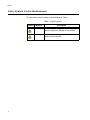


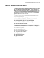


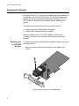
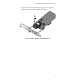
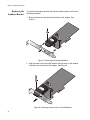


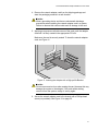
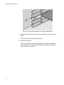

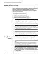
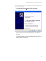
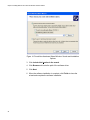

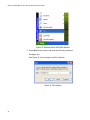
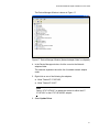
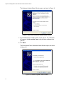

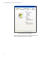


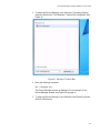
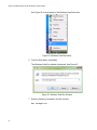
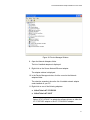


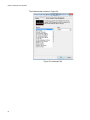
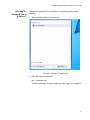


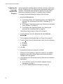
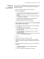

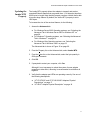
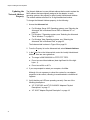

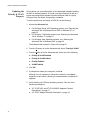


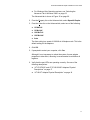
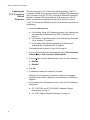
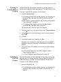


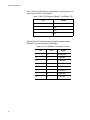


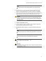
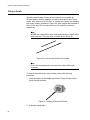


![[inetdoc.LINUX]](http://vs1.manualzilla.com/store/data/006320752_1-a5dc0c2518595df6f6d4df8e955edfdb-150x150.png)