1
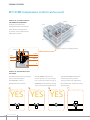
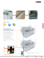
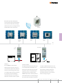
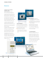
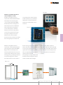
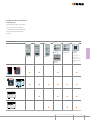
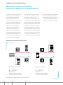
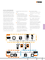
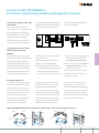
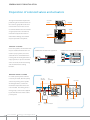
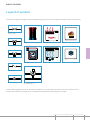
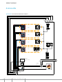
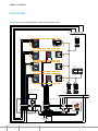
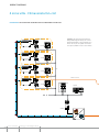
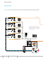
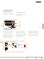
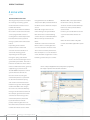
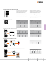
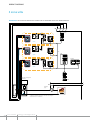
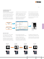
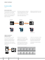
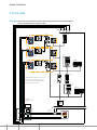
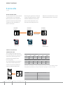
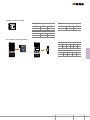
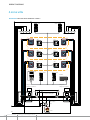
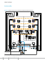
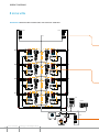
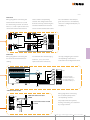
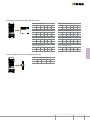
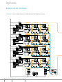
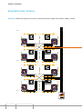
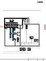
226 MY HOME Energy management CONTENTS MY HOME – Energy management General features. . . . . . . . . . . . . . . . . . . . . . 228 Temperature control . . . . . . . . . . . . . . . . . . . 235 Air conditioning. . . . . . . . . . . . . . . . . . . . . . 287 Energy consumption display. . . . . . . . . . . . . . 291 Load control management. . . . . . . . . . . . . . . 301 Energy management MY HOME 227 GENERAL FEATUREs saving energy has never been this easy MY HOME, the winning combination Displaying information on energy very much more aware of their consumption and managing and energy use, be it to meet their “green controlling energy loads; this is aspirations” or their desire to make whAT THE NEw My Home solutions financial savings deliver to end users - making them Visibility drives savings An aware user is one that saves changing there (bad) routines or with resulting benefits for the correcting faults which result in environment and in reduced costs savings of 10 to 15% studies have shown that displaying energy consumption results in users 228 MY HOME Energy management My Home enables you to: Create a living space with maximum comfort, only using the necessary energy and heat Improve the energy class of the building, and therefore also of its economic value Multimedia Touch Screen Touch Screen Energy management MY HOME 229 GENERAL FEATUREs To ensure energy efficiency with MY HOME is easy BUS-SCS MY HOME TV/SAT IPTV Heating only when and where needed Using this function, the user can decide the antifurto Zone temperature termoregolazione control videocitofonia controllo lan controllo carichi temperature of each individual room based on its energia luci tvcc use and the time of day It is also possible to select the rooms that are not being used, and therefore don’t need to be heated The activation of the system also takes into account the heat produced by the sun uP to 30% sAVings switch lights off, switch savings on energia Light automation luci management Management of www lighting depending on the tvcc irrigazione presence of people and the level of natural light: this provides maximum visual comfort for the users and greatly contributing to energy savings Depending on the space, savings of 55% to 75% are possible BUS-SCS MY HOME 230 MY HOME Energy management uP to 75% sAVings www irrigazione ne TV/SAT IPTV A complete consumption and energy production check-up The user can display on the touch screen not only the videocitofonia controllo lan controllo carichi Consumption energia display luci tvcc www irrigazione consumptions inside their home (power, water and gas1)), but also the energy and hot water ouput obtained using photovoltaic or solar panels uP to 15% sAVings With a few simple steps, the user can select the type of consumption that needs to be checked, the type of display (instantaneous or graphs), and the period (day, month, year) Extremely useful information, for using one’s own systems at their best, reducing waste and faults TV/SAT IPTV NOTE: 1) subject to type of meters installed for gas and water. New heading required This function can be used to manage the maximum termoregolazione videocitofonia controllo lan Management of loads controllo carichi power to be used, and automatically disconnect the least energia luci tvcc www important appliances in case of overload irrigazione Using the Touch screens, the user can check the total consumption of the individual circuit, and decide if the priorities need changing The user can also decide to delay the activation of a particular load Energy management MY HOME 231 GENERAL FEATUREs Energy efficiency management devices overview Splitter Probe Local Display Splitter management interface 99 zone central unit Distribution board Room-by-room temperature control Zone temperature control Probe 99 zone central unit 232 MY HOME Energy management Air conditioning Splitter management Splitter interface Touch Screen Washing machine Photovoltaic panel Thermal solar panels Microwave Flush mounted 16A actuator Bus meter with toroids Pulse counter interface Pulse counter interface Pulse counter interface Touch Screen Water meter with pulse output Gas meter with pulse output Automatic switching off of heating when windows are opened Consumption and production display Irrigation management Load control management m3/€ m3/€ KWh/€ Touch Screen KWh Kcal Central unit for load management Energy management MY HOME 233 234 MY HOME Energy management CONTENTS MY HOME – Temperature control General features. . . . . . . . . . . . . . . . . . . . . . 236 General rules for installation . . . . . . . . . . . . . . 244 Wiring diagrams. . . . . . . . . . . . . . . . . . . . . . 249 Configuration . . . . . . . . . . . . . . . . . . . . . . . . 285 Energy management MY HOME 235 GENERAL FEATUREs MY HOME temperature control can be used: WHEN THE SYSTEM IS PRESET Bathroom FOR ZONE MANAgEMENT Kitchen A system is preset for zone Bedroom management when the solenoid valves for the management of each zone can be installed on the distribution collector Hall Solenoid valve Living room A system is divided into Zones with radiant panel heating Collector Bedroom Collector Kitchen Bathroom Living room Box WHEN THE SOLENOID vALvES USED ARE: The solenoid valves that manage the The MY HOME temperature from the MY HOME temperature zones can be of two types: control system can also manage control system; they need an 1. with ON/OFF contacts the circulation pumps (see Fig 3) external control unit, supplied by 2. With open/close contacts WARNING: The proportional mixing the manufacturer of radiant heating valves cannot be managed directly panel systems 1 2 3 YEs YEs YEs 4 M M 236 MY HOME IN SYSTEMS WITH: Radiators Radiant panels Fan-coil WITH SYSTEMS OF: Heating Bathroom Cooling Both Kitchen Bedroom IN CENTRAL HEATINg SYSTEMS WITH DISTRIbUTION COLLECTOR FOR EACH HOME In central heating systems where each Home is fitted with its own Hall distribution collector, it is possible to: Living room by installing a meter on the collector input, measure the amount of heat used; by installing solenoid valves, to manage the different zones of the Home Bathroom Kitchen Bedroom Hall Distribution collector Living room Zone solenoid valve Meter Example of central heating system split into zones, for several apartments. Main boiler Energy management MY HOME 237 GENERAL FEATUREs Devices The MY HOME temperature control system consists of the following devices: Power supply Temperature central unit Probes: Probes they must be installed in each zone, Actuators so that the temperature of the rooms Contact interface (OPTIONAL) can be detected and if necessary locally changed, in relation to the temperature set on the control unit Power supply 99 zone central unit Power supply: Temperature control unit: for MY HOME systems this is the unit used for system Zone 1 probe 2 relay actuator configuration, program customisation, and the display of information This is available in the catalogue in the 4 zone flushmounting version or in the 99 zone wall-mounting version Actuators: activate the solenoid valves and the circulation pumps The number and type of actuators depends on the type of solenoid valves installed, and their positioning within the system 238 MY HOME Energy management External temperature radio probe: it measures the external temperature and sends the information, through radio waves, to the receiving interface, Outdoor radio probe and therefore to the control unit Zone 2 probe External radio probe interface Zone 99 probe Local Display BUS 4 relay actuator Contact interface Actuators: Contact interface: For the ON/OFF control of the this optional device detects the open are open With this function one can solenoid valves only one contact is or closed position of windows and make the most of each energy saving used, while for open/close solenoid doors by assessing the status of their opportunity, avoiding unwanted valves the interlocking of two relays magnetic contact The information dispersion of heat to the outside, is used By using the 4 relay actuator, obtained is then used by the MY for example when the air inside the it is possible to control both the HOME temperature control system to house is being changed activation of the fan-coils and the switch off the zones corresponding to automatic selection of the 3 speeds the rooms where windows and doors Energy management MY HOME 239 GENERAL FEATUREs Devices Adjustable probe TEMPERATURE CONTROL CENTRAL UNITS The two temperature control Local Display units ensure simple management/ programming of the whole system; in this way, thanks to a guided menu, it will be possible to select the operating mode, display the temperatures of the various zones, and change the possibility of managing the daily and weekly programs Inside the operating mode (OFF; antifreeze/ 4 zone control unit is a probe This thermal protection, and automatic) is a zone in itself, and it is therefore possibility of controlling the speed possible to connect three more probes, before the maximum number of probs that can be managed by the device is reached In addition to being able to manage temperature control systems, both in heating and cooling mode, the LOCAL CONTROL of the FAN-COILs A probe is installed in each room, for All these functions may also be the measurement of the temperature performed using Local Display, Probe models fitted with a knob also a recently launched Oled Touch provide easy system control: screen technology control device, possibility of changing the connected to a probe 99 zone control unit is also capable, thanks to the scenarioso mode, of setting different temperatures in temperature by ±3° C compared with the value set on the control unit PC PROgRAMMINg TiThermo and TiThermo Basic are the different zones of the system, by programs that enable the user to means of a single control (e g maid program and configure the control scenarioso) 16 scenariosos for the 4 zone central unit units, by setting and customising winter and 16 scenariosos for the the parameters connected with the summer can be set temperature control system Thanks 99 zone central unit to a dedicated function, the software can also be used to update the firmware of the control unit Bticino software 240 MY HOME Energy management Video Station PERFECT INTEgRATION WITH THE MY HOME SYSTEM Example of integration between (e g weekly mode, external probe Temperature Control and Automation scenarioso mode, etc ) For further The temperature control system information see the User Manual can be integrated with MY HOME supplied as standard with Touch Automation, for the management screen IP of the temperature in the different zones of the house, using Touch Touch Screen screen, Videostation, and Video Display In particular, using Touch screen IP it is possible to manage not only the temperature in the different zones, but also those functions that up to now have always been managed by the control unit Example of integration between house is being changed In practical Alarm system, which reads the Temperature Control and Automation terms, when doors or windows of condition of the NC contact installed The integration between MY HOME a room are opened, the heating on the door or window, and transfers Burglar-Alarm and Temperature system of the temperature control the information to the Temperature Control systems allows the set-up of zone corresponding to that room is Control system for the appropriate a particularly useful function in terms automatically turned off actions of energy saving, avoiding unwanted The opening or closing of doors and escape of energy to the outside, windows is detected by the contact for example when the air inside the interface module of the Burglar- Magnetic contact Contact interface Opening of window Radiator off Temperature control unit Energy management MY HOME 241 GENERAL FEATUREs Device selection criteria gUIDE TO THE SELECTION OF THE CONTROL UNIT The following table shows the the number of zones of the hydraulic functions provided by the two system Other selection parameters control units The selection must be may be the management of magnetic based on the features of the system contacts, remote control, etc It is fundamental that the selection of the control unit should be based on available funCtionS 4 Zone Central unit 99 Zone Central unit HC/HS/L/N/NT4695, AM5875 3550 Maximum number of zones Remote control Local control (Touch Screen) Programming with TiThermo Basic Programming with TiThermo Magnetic contacts management Scenarios Climaveneta Chiller Management 242 MY HOME Energy management 4 99 gUIDE TO THE SELECTION OF THE DEvICES The following table summarizes the various types of systems, and the devices needed for their management, based on their features type of SyStem aCtuator probe HC/HS4692 L/N/NT4692 F430/2 F430/4 Gateway HC/HS4693 L/N/NT4693 HC/HS4692FAN L/N/NT4692FAN HC/HS4685 L/N/NT4685 In conjunction with probe item HC/ HS4693, L/N/ NT4693, or with external probe item 3457 Radiators or Radiant panels Combined system with radiant panels and fan-coils Normal Fan-coil CLIMAVENETA Fan-coil WARNING: protect the outputs of the relay actuators using a 10 A thermal magnetic circuit breaker, included in the BTDIN catalogue with item no. F881NA/10. Energy management MY HOME 243 GENERAL RULEs FOR INsTALLATION Maximum number of devices, maximum distances and absorptions A system can manage up to 99 zone the items and making sure that the addresses Up to nine addresses total does not exceed the capacity dedicated to the actuators can of the power supply For the be managed for each zone The calculations mentioned above, refer on the BUs line the power supply maximum number of devices which to the TECHNICAL DATA listed in the should be installed in the middle can be connected to the BUs also Technical sheets section of this guide depends on their total absorption When calculating the absorptions the and the distance between the availability of current as a function connection point and the power of the length of the BUs cable must supply The power supply can also be considered During the sizing supply up to 1200 mA (E46ADCN) therefore respect the following rules: or 600 mA (E49) and the maximum the connection between the power the total length of the connections must not be more than 500m; for best division of the currents number of devices which can be supply and the furthest device connected to the BUs is determined must not be more than 250 m long; by summing the absorption of all MAXIMUM DISTANCES OF THE bUS CAbLE 1 2 3 4 1 2 3 4 ART. F430/2 C1 C2 -3 -2 -1 +1 -2 -1 +1 A 1 4 7 OF F +3 +2 +3 +2 F -3 OK OF 2 5 8 0 3 6 9 A PRI E49 PRI: 220 – 240 V~ 185 – 175 mA 50/60 Hz SCS: 27 Vdc 600 mA b E46ADCN b SCS -3 -2 -1 OF +3 +2 +1 -2 -1 +3 +2 F -3 E49 OF F 1 2 3 4 1 2 3 4 +1 ART. F430/2 C1 OK 1 4 7 2 5 8 0 3 6 9 With power supply E46ADCN: With power supply E49: A =250 m max A =250 m max b =250 m max b =250 m max A + b =500 m Maximum current supplied by the power supply: 1200 mA NOTE: If a UTP5 cable is used instead of a BUS L4669 cable, distances must halved. 244 MY HOME Energy management A + b =500 m Maximum current supplied by the power supply: 600 mA C2 PHYSICAL EXPANSION MODE In large systems or systems which use of the interface itself as indicated have current absorption greater than below: Automation device addresses must the limit of 1200 mA supplied by the If a bus system with only be between A = 1 / PL = 1 and A = on the input bus (IN) the power supply E46ADCN or 600 mA temperature control devices must supplied by the E49 compact power be extended, positions I3 and I4 of supply, split the system into several the interface must be configured addresses must be between A = 3 / sections connected to each other with addresses I3 = 1 – 9 and I4 = PL = 3 and A = 9 / PL = 9 or the using the F422 interface configured 1 – 9 completely independent from address of the next interface. It in “physical expansion” mode. It the Temperature control device should be stressed that all the is important to remember that addresses; temperature control devices on the each line must be powered by its 3 / PL = 1; on the output bus (OUT) the system section must be configured If a bus system with Automation own power supply. To produce the and temperature control devices totally independently of the “physical expansion” mode interface must be extended, positions I3 Automation device configuration. item F422 must be configured by and I4 must be configured as a In any case no automation device inserting numeric configurator 1 in function of the configuration of must be configured with the same the MOD position. Positions I3 and I4 the Automation devices in the two address (A, PL) as interface F422 of the interface must be configured connected systems. Referring to (I3, I4). as a function of the two modes of the illustration, let us suppose that I3 = 3, I4 = 2: A/PL = 33 53 1 2 3 4 1 2 3 4 ART. F430/2 C1 C2 -2 -1 F422 OUT +1 F 2 5 8 0 3 6 9 I1 = – I2 = – I3 = 5 I4 = 4 MOD = 1 -3 AR T.F422 OF +3 +2 -2 -1 OF +3 +2 +1 A/PL = 11 31 IN I1 = – I2 = – I3 = 3 I4 = 2 MOD = 1 -3 AR T.F422 F -2 -1 +1 OUT OUT +3 +2 F422 -3 OK 1 4 7 OF F A/PL = 55 99 Energy management MY HOME 245 General rules for installation Combining with other functions The Temperature control function The above is also valid if the this document. For systems which devices can share the same BUS pre-existing MY HOME system also have the burglar-alarm function, cable as other MY HOME automation has several Automation systems the Temperature control must not and emergency management connected using interfaces item F422 be installed on the same bus as the applications (grey cable). If there configured in the “logical expansion” burglar-alarm, but there must be is already a stable cable with the mode. an F422 interface between the two automation or power management For systems with “logical expansion” buses. BUS the Temperature control items there is no installation limitation for can be added at any point in the the Temperature control devices, system, after installing a box item which can be installed at any point 503E for the control units, one or in the system.Thus, for correct more boxes positioned at a height system sizing, one only need check of 1.5 m for each temperature probe the length of the connections made and a unit with enough room for the with the BUS cable and the total DIN actuators. device absorptions as specified in A/PL = 11 99 OUT OUT +1 -3 -2 -1 F OF +3 +2 -2 -1 +3 +2 OF -3 AR T.F422 ZA = 1 ZB = 1 F ZA = 1 ZB = 1 I1 = – I2 = – I3 = – I4 = 1 MOD = 2 +1 OK IN 1 4 7 AR T.F422 -3 F +1 -2 -1 +3 +2 OF +1 IN 1 2 3 4 1 2 3 4 ART. F430/2 C1 OUT OUT OUT ˜2 24h 1 TEST S PROG AUX P 3 AR T.F422 4 IN 246 MY HOME Energy management I1 = – I2 = – I3 = – I4 = 1 MOD = 4 C2 OF +3 +2 OUT ZA = 2 ZB = 1 I1 = – I2 = – I3 = – I4 = 2 MOD = 2 -2 -1 OUT -3 A/PL = 11 99 F 2 5 8 0 3 6 9 ZA = 3 ZB = 2 Correct mode of installation for 4 zone control unit, probes and magnetic contacts The 4 ZONE CONTROL UNIT and wall-mounting boxes (LIVING, LIGHT, with pre-existing BUS systems that the Probes LIGHT TECH only); Surface installation cannot be expanded. must be installed at a height of may be useful for resolving issues approximately 1.5 m, away from areas that may affect the reading of the -3 +1 -2 -1 OFF +1 -3 +3 +2 -2 -1 -3 -2 -1 OFF -2 -1 OFF +3 +2 +1 +1 inside standard flush-mounting, or +3 +2 The probes may be installed both OFF +3 +2 windows, fan-coils, or radiators. -3 room temperature, such as nearby 1,5m CALIBRATION OF THE 4 ZONE CENTRAL UNIT AND THE PROBES The probes and the 4 zone central function, which can be found in the room temperature (e.g. by opening unit do not normally need calibration; central unit menu. or closing windows, doors, etc.) however, in particular installation Before performing the calibration and avoid standing near them; situations (perimeter walls, north operation, ensure the following: or south facing walls, when close to Leave the probes connected and for the calibration use a calibrated sample thermometer, correctly placed inside the room. heat sources, etc.), the temperature powered with the hydraulic system value measured may be corrected off for at least two hours. During For more details on the calibration using the appropriate calibration this time, avoid any changes in the procedure, refer to the central unit installation manuals. Magnetic contacts are generally installed in the upper protection line generally not used If the contact interface is correctly part of the window frames and in in temperature control. It is mainly configured it can support both the point furthest away from the useful for preventing tampering applications. When the temperature hinges. In this way small openings such as cutting the wires in burglar- control system is being installed the cause the magnet to move away alarm systems. If the same MY HOME protection line should be installed from the contact reed and the system has temperature control and and wired as well, so that the burglar- contact itself consequently opens. burglar-alarm applications the same alarm can be installed as well. The models in the catalogue magnetic contacts can be used for are of NC type and also have a both functions at the same time. For flush-mounting installation 3510, 3510M, 3510PB For visible installation 3511 Magnet Contact Magnet Contact Magnet Contact Contact Protection line NC contact Magnet Protection line NC contact Energy management MY HOME 247 GENERAL RULEs FOR INsTALLATION Disposition of solenoid valves and actuators The typical installation requires the Solenoid valve actuators positioning of all solenoid valves on 1 2 3 4 1 2 3 4 1 2 3 4 1 2 3 4 ART.F430/2 C1 C2 1 2 3 4 1 2 3 1 2 3 4 4 ART.F430/2 C1 C2 1 2 3 4 ART.F430/2 C1 C2 ART.F430/2 Plug-in box C1 C2 the collector, grouped inside a box in the boiler room In this case it is recommended that also all actuators Hydraulic collector are grouped, inside a control unit, installed nearby the box itself In Zone solenoid valve multi-floor buildings, this solution may be repeated at every floor Box FAN-COIL SYSTEMS In fan-coil systems, the solenoid valve may be installed inside the fan-coil Installation of the solenoid valve inside 2 pipe fan-coils Installation of the solenoid valve inside 4 pipe fan-coils itself In 2 pipe systems, the same solenoid valve is used both for the heating and the cooling functions In 4 pipe systems, 2 separate solenoid M M valves are used, one for the heating and the other for the cooling function RADIANT PANEL SYSTEMS In radiant panel systems it will be necessary to install, after the pump, a three-way mixing valve capable Three-way mixing valve Zone solenoid valve Actuators Circuit breaker of mixing the water, so that the maximum temperature limit set is not exceeded The mixing valve is managed by a central unit supplied by the manufacturer of the radiant M panel system To the zone radiant panels 230 Vac To other devices Circulation pump 248 MY HOME Energy management Mixing valve management central unit Power supply Wiring diagrams Legend of symbols To make the reading of the diagrams shown in the following pages easier, the various symbols and their functions are summarised. General valve symbol Radiators Electric radiator Boiler Radiant panels Fan-coil Chiller ON/OFF solenoid valve M Open/close solenoid valve Non-return valve Pump M Three-way mixing valve (*) (*) NOTE: In radiant heating panel systems this valve has the function of mixing water, to ensure that the water itself, and therefore also the floor, remain below a certain temperature limit. For this reason, the mixing valve must be controlled by a control unit supplied by the radiant heating panel system supplier. Energy management MY HOME 249 Wiring diagrams 4 zone villa DIAGRAM 1 HEATING WITH RADIATORS C4 C3 1 2 3 C2 4 C1 5 1 2 3 4 5 ART. F430/4 C1 C2 C3 C4 ZONE 4 -2 -1 OF F +3 +2 +1 Solenoid valve -3 F430/4 -2 -1 +1 Solenoid valve OF F +3 +2 ZONE 3 -3 4692 4692 -2 -1 +1 Solenoid valve OF +3 +2 ZONE 2 -3 BUS F E46ADCN 4692 18.0°C ZONE 1 Solenoid valve 23.7°C 13 : 38 C Ven 07 Gen OK 4695 1 2 3 4 1 2 3 4 ART. F430/2 C1 C2 F430/2 L N C1 Circulation pump Boiler 250 MY HOME Energy management Central unit/probe configuration 18.0°C 23.7 13 : 38 Ven °C 07 Gen OK C The 4 zone control unit item HD/HC/ the system configuration operations HS/L/N/NT4695 and item AM5875, correctly. as well as managing the whole of the As an alternative the TiThermo Basic temperature control system, contains application dedicated to this version a temperature probe which must of control unit can be used. be configured physically like the For these operations refer to the other system probes. Interact with manual supplied with the products. the “Configure zones” menu to end Zone 1 Central unit/probe [ZA] [ZB] [SLA] 0 1 - [ZA] [ZB] [SLA] 0 2 - [ZA] [ZB] [SLA] 0 3 - [ZA] [ZB] [SLA] 0 4 - PROBES configuration -3 Zone 2 probe -2 -1 +3 +2 OF F +1 Zone 3 probe Zone 4 probe Actuators configuration Zone actuator 1 2 3 1 2 3 4 5 4 5 1 2 1 2 3 4 3 ART. F430/4 C1 C2 C3 C4 4 ART. F430/2 C1 C2 [ZA] [ZB1] [ZB2] [ZB3] [ZB4] [N] 0 1 2 3 4 1 Circulation pump actuator [ZA] [ZB1] [N1] [ZB2] [N2] 0 0 1 OFF - Energy management MY HOME 251 Wiring diagrams 4 zone villa DIAGRAM 2 Heating with Radiant panels C4 C3 1 2 3 C2 4 C1 5 1 2 3 4 5 ART. F430/4 -3 C1 C2 C3 C4 -2 -1 OF +3 +2 F +1 ZONE 4 F430/4 -3 4692 -2 -1 OF +3 +2 F +1 ZONE 3 4692 -2 -1 OF +3 +2 +1 ZONE 2 -3 BUS F E46ADCN 4692 18.0°C 23.7°C ZONE 1 13 : 38 C Ven 07 Gen OK 4695 1 2 3 4 1 2 3 4 ART. F430/2 C1 C2 F430/2 Mixing valve management central unit M L C1 N Circulation pump Boiler Distribution collector with solenoid valves 252 MY HOME Energy management Central unit/probe configuration 18.0°C 23.7°C 13 : 38 Ven 07 Gen OK C The 4 zone control unit item HD/HC/ correctly. As an alternative the HS/L/N/NT4695 and item AM5875, TiThermo Basic application dedicated as well as managing the whole of the to this version of control unit can temperature control system, contains be used. For these operations refer a temperature probe which must to the manual supplied with the be configured physically like the products. other system probes. Interact with the “Configure zones” menu to end the system configuration operations Zone 1 Central unit/probe [ZA] [ZB] [SLA] 0 1 - [ZA] [ZB] [SLA] 0 2 - [ZA] [ZB] [SLA] 0 3 - [ZA] [ZB] [SLA] 0 4 - PROBES configuration -3 Zone 2 probe -2 -1 +3 +2 OF F +1 Zone 3 probe Zone 4 probe Actuators configuration Zone actuator 1 2 3 1 2 3 4 5 4 5 1 2 1 2 3 4 3 ART. F430/4 C1 C2 C3 C4 4 ART. F430/2 C1 C2 [ZA] [ZB1] [ZB2] [ZB3] [ZB4] [N] 0 1 2 3 4 1 Circulation pump actuator [ZA] [ZB1] [N1] [ZB2] [N2] 0 0 1 OFF - Energy management MY HOME 253 Wiring diagrams 4 zone villa DIAGRAM 3 Heating with Radiant panels and heating units C1 ZONE 1 C2 C3 4695 1 2 3 4 C4 5 1 2 3 4 5 ART. F430/4 18.0°C 23.7 °C 13 38 : Ven C1 07 C2 C3 C4 Gen OK C F430/4 4692 -3 ZONE 2 -2 -1 OF +1 +3 +2 F BUS -2 -1 OF E46ADCN F +1 +3 +2 ZONE 4 -3 4692 4692 -3 ZONE 3 -2 -1 +3 +2 OF F +1 1 2 3 4 1 2 3 4 1 2 3 C1 Mixing valve management central unit ART. F430/2 C1 C2 F430/2 C2 F430/2 L C1 N Heating units distribution collector M Circulation pumps Distribution collector with solenoid valves C1 254 MY HOME Energy management C2 4 1 2 3 4 ART. F430/2 C2 Boiler Central unit/probe configuration 18.0°C 23.7 13 : 38 Ven °C 07 Gen OK C The 4 zone control unit item HD/HC/ correctly. As an alternative the HS/L/N/NT4695 and item AM5875, TiThermo Basic application dedicated as well as managing the whole of the to this version of control unit can temperature control system, contains be used. For these operations refer a temperature probe which must to the manual supplied with the be configured physically like the products. other system probes. Interact with the “Configure zones” menu to end the system configuration operations Zone 1 Central unit/probe [ZA] [ZB] [SLA] 0 1 - [ZA] [ZB] [SLA] 0 2 - [ZA] [ZB] [SLA] 0 3 - [ZA] [ZB] [SLA] 0 4 - PROBES configuration -3 Zone 2 probe -2 -1 +3 +2 OF F +1 Zone 3 probe Zone 4 probe Actuators configuration 1 2 3 1 2 3 4 5 4 1 5 2 1 2 3 4 3 C1 1 4 2 1 2 3 4 3 C1 C2 C3 C4 Zone actuator 4 ART. F430/2 ART. F430/2 ART. F430/4 C1 C2 Circulation pump actuator C2 HEATING UNITS actuator [ZA] [ZB1] [ZB2] [ZB3] [ZB4] [N] [ZA] [ZB1] [N1] [ZB2] [N2] [ZA] [ZB1] [N1] [ZB2] [N2] 0 1 2 3 4 1 0 0 1 0 2 0 2 1 4 1 Energy management MY HOME 255 Wiring diagrams 4 zone villa - Climaveneta fan-coil DIAGRAM 4 HEATING AND COOLING WITH CLIMAVENETA FAN-COIL (*) NOTE: the Gateway is fitted inside the FAN-COIL during manufacturing, and is already connected to the FAN-COIL itself through the collector found at the top on the front. Therefore, once the hydraulic connection has been completed, all that is needed is to connect the BUS. -2 -1 OF F +3 +2 +1 4692FAN -3 (*) ZONE 4 GATEWAY -2 -1 OF F +3 +2 +1 4692FAN -3 (*) ZONE 3 GATEWAY (*) ZONE 2 -3 BUS -2 -1 OF F +3 +2 +1 4692FAN GATEWAY (*) ZONE 1 FAN-COIL connection -3 3550 -2 -1 OF +3 +2 +1 4692FAN F E46ADCN GATEWAY OK 1 4 7 2 5 8 0 3 6 9 GATEWAY CHILLER 256 MY HOME Energy management 99 zone central unit configuration OK 1 4 7 2 5 8 0 The 99 zone control unit item 3550 As an alternative the TiThermo does not need physical configurators application can be used. For these but, to end the system configuration operations refer to the manual operations, interact with the supplied with the products. “Configure zones” menu. 3 6 9 Configuration of probes for fan-coil -3 Zone 1 probe -2 -1 +3 +2 OF F Zone 3 probe [ZA] [ZB] [SLA] [ZA] [ZB] [SLA] 0 1 - 0 3 - [ZA] [ZB] [SLA] [ZA] [ZB] [SLA] 0 2 - 0 4 - +1 Zone 2 probe HEATING AND COOLING WITH CLIMAVENETA FAN-COIL Gateway M Zone 4 probe Electric diagram and configuration all other zones, perform the same of the GATEWAY installed inside the type of connection, ensuring correct Climaveneta fan-coil for the heating- configuration of the actuator for cooling of zone 2. the specific zone, as shown in the In order to control the fan-coils of configuration tables. Zone 1 gateway Zone 3 gateway [ZA] [ZB] [N] [TYPE] [ZA] [ZB] [N] [TYPE] 0 1 1 0 0 3 1 0 [ZA] [ZB] [N] [TYPE] [ZA] [ZB] [N] [TYPE] 0 2 1 0 0 4 1 0 Zone 2 gateway BUS climaveneta CHILLER Zone 2 gateway Wiring diagram and configuration chiller. With one chiller, a system of the gateway which controls the can be slaved and operate both as a heating system and as a cooling system. The Gateway is connected to the CLIMAVENETA chiller through Climaveneta the collector found at the top on the CHILLER front, and to the BUS through the draw-out connection terminal. Gateway BUS Gateway chiller [ZA] [ZB] [N] [TYPE] 0 0 1 1 Energy management MY HOME 257 Wiring diagrams 4 zone villa DIAGRAM 5 HEATING AND COOLING WITH CLIMAVENETA AIR CONDITIONING AND COMBINATION BOILER (*) ZONE 4 -3 FAN-COIL connection -2 -1 OF +3 +2 F +1 4692FAN GATEWAY -3 (*) ZONE 3 -2 -1 OF +3 +2 F +1 4692FAN GATEWAY (*) NOTE: the Gateway is fitted inside the FAN-COIL during manufacturing, and is already connected to the FAN-COIL itself through the collector found at the top on the front. Therefore, once the hydraulic connection has been completed, all that is needed is to connect the BUS. -3 (*) ZONE 2 -2 -1 OF +3 +2 F +1 4692FAN GATEWAY 3550 E46ADCN (*) ZONE 1 -3 OK -2 -1 +3 +2 OF F 1 4 7 2 5 8 0 3 6 9 +1 4692FAN GATEWAY F430/2 GATEWAY C1 C2 ART. F430/2 1 2 3 4 1 2 3 4 Combination boiler 3 way solenoid valve 258 MY HOME Energy management CHILLER next >> Heating and cooling with CLIMAVENETA FAN-COIL Electric diagram and configuration Correctly configures the gateway of the GATEWAY installed inside the corresponding to the zone as heating/cooling Climaveneta fan-coil. indicated in the configuration tables of the following pages. M GATEWAY BUS CLIMAVENETA CHILLER Wiring diagram of the gateway which There is thus no need to install The Gateway is connected to the controls the chiller. A single chiller radio probe item 3455 with its CLIMAVENETA chiller through the serves a system which can work interface. The temperature datum collector found at the top on the both as heating and as cooling. The is made available to the MY HOME front, and to the BUS through the attached outside temperature probe temperature control system by draw-out connection terminal. is a device normally present in a means of the gateway. Climaveneta system of this type. Climaveneta CHILLER 5° C GATEWAY BUS Energy management MY HOME 259 WIRING DIAGRAMs 4 zone villa < previous DIAgRAM DESCRIPTION This diagram represents an example Using TiThermo set the Outside ON, Boiler OFF, valve open towards of a heating and cooling system Temperature (OT) value below which the Chiller To sum up, the Chiller made with Climaveneta unit and the Boiler starts to work: for example continues to work until the OT drops Combination boiler set 5°C below 5°C; at this point the Boiler By means of the TiThermo software When OT is higher than 5°C the starts to work the 99 zone control unit item 3550 Chiller manages the system When It will stay on until the OT rises above can be programmed to use the OT is lower than 5°C the following 7°C, when the Chiller switches on reading of the outside temperature actions take place: Chiller OFF, Boiler again from the Climaveneta system to ON and valve open towards the manage systems with combination Boiler NOTE: for the TiThermo software setting details boilers The Boiler continues to work until consult the documentation supplied with the product Depending on the outside OT rises above a value higher than itself. temperature the control unit 5°C This selection is made to avoid activates the most suitable and device state oscillation phenomena convenient heating system If for example 7°C is set as threshold depending on the heat yield value, when OT is higher than 7°C the During the spring and autumn following actions take place: Chiller rooms can be heated using the heat generated by the Chiller This heat is however not suffi cient in the winter when a Combination boiler, generally TiThermo: example of an application window, indispensable for programming supplied by gas, must be used and setting the temperature thresholds and the automations. The MY HOME temperature control system switches between the two sources of heat, using the outside temperature as parameter to discriminate between spring and autumn and winter Actuator F430/2 manages the switching ON or OFF of the Boiler and changes the valve state, while the Gateway manages the Climaveneta Chiller In the example given here the Chiller continues to work as long as the outside temperature (measured by the Climaveneta outside probe) remains higher than a set threshold value; below this value the Combination boiler starts to work 260 MY HOME Energy management 99 zone central unit configuration OK 1 4 7 2 5 8 0 3 6 9 The 99 zone control unit item 3350 This device does not need physical must be used to manage systems configurators but, to end the system with combination boiler. The configuration operations, interact function is not in fact available on with the “Configure zones” menu the 4 zone control unit item HC/ and with TiThermo applications. For HS/L/N/NT4695 and item AM5875. these operations refer to the manual supplied with the products. PROBES configuration -3 Zone 1 probe -2 -1 +3 +2 OF F Zone 3 probe [ZA] [ZB] [SLA] [ZA] [ZB] [SLA] 0 1 - 0 3 - +1 Zone 2 probe Zone 4 probe [ZA] [ZB] [SLA] [ZA] [ZB] [SLA] 0 2 - 0 4 - GATEWAY FAN-COIL configuration Zonef1 gateway Zone 3 gateway [ZA] [ZB] [N] [TYPE] [ZA] [ZB] [N] [TYPE] 0 1 1 0 0 3 1 0 [ZA] [ZB] [N] [TYPE] [ZA] [ZB] [N] [TYPE] 0 2 1 0 0 4 1 0 Zone 2 gateway Zone 2 gateway GATEWAY CHILLER configuration 6° C Gateway chiller [ZA] [ZB] [N] [TYPE] 0 0 1 1 Boiler and solenoid valve actuator configuration Boiler/solenoid valve actuator 1 2 1 2 3 4 3 4 ART. F430/2 C1 [ZA] [ZB1] [N1] [ZB2] [N2] 0 5 1 6 1 C2 RISCALDAMENTO Energy management MY HOME 261 Wiring diagrams 3 zone villa DIAGRAM 6 Heating with Radiant panels WITH WINDOW CONTACT MANAGEMENT C4 C3 C2 C1 F430/4 (*) 1 T - C1 - C2 4692 C1 5 C2 C3 C4 -2 -1 OF F +3 +2 +1 C2 C1 4 ART. F430/4 ART.F482 T 3 -3 C1 2 1 2 3 4 5 F482 (*) 4692 -2 -1 OF F +3 +2 C2 -3 ZONE 3 BUS +1 3550 ZONE 2 (*) T - C1 - C2 OK -2 -1 +1 C2 C1 2 5 8 0 OF +3 +2 T ZONE 1 1 4 7 ART.F482 -3 C1 E46ADCN 4692 F 3 6 9 F482 1 2 1 2 3 4 3 4 ART. F430/2 C1 Mixing valve management central unit C2 F430/2 L C1 M N Circulation pump Boiler (*) NOTE: the maximum length of the connections to the magnetic contacts must not exceed 50 metres. 262 MY HOME Energy management next >> 99 ZONE CENTRAL UNIT CONFIgURATION The 99 zone control unit item 3350 configurators but, to end the system When setting the parameters for must be used to use the magnetic configuration operations, interact the management of the magnetic contact management function The with the “Configure zones” menu contacts, the TiThermo application function is not in fact available on As an alternative the TiThermo must be used Two parameters may the 4 zone control unit item HC/ application can be used For these be set: the reaction time, and the Hs/L/N/NT4695 and item AM5875 operations refer to the manual reactivation time This device does not need physical supplied with the products REACTION TIME OK 1 4 7 REACTIvATION TIME 2 5 8 0 3 6 9 Temperature central unit item 3550 TiThermo screen REACTION TIME The reaction time can be set from frame avoiding switching the needed for the changes of air, for 0 to 2 minutes and is a sort of corresponding temperature control example opening a window to close delay to the deactivation of the zone OFF setting 0 minutes or open the shutters, or opening the temperature control zone During deactivation is practically instant entrance door to welcome a person this time the system completely This function is suitable for short ignores the opening of the window openings of windows or doors not WINDOW CLOsED WINDOW OPENING WINDOW CLOsING WINDOW CLOsED t = 0÷2 time can be set from 0 to 2 minutes radiant panel ON radiant panel kept ON radiant panel kept ON radiant panel ON Energy management MY HOME 263 Wiring diagrams 3 zone villa < previous Reactivation time The reactivation time can be set from Even if it goes against the concept of When the reactivation time is set on 5 to 55 minutes, or on unlimited. energy saving this function is useful unlimited the function is not active. When the time set has elapsed the when the windows have been left system reactivates the temperature open and the temperature set in the control zone even if windows or room must be kept the same. doors are still open. WINDOW CLOSED WINDOW OPENING WINDOW LEFT OPEN t = 5÷∞ time can be set from 5 minutes to unlimited radiant panel ON radiant panel OFF radiant panel back ON automatically Contact interface configuration The contact interface is directly Follow by connecting the AUX address 1 to 99 of the device, within connected to the temperature configurator to the MOD1 and/or the system. The coupling between control bus. It autonomously and MOD2 housings, for the activation the interface contact line and the independently manages the two of the operating mode with temperature control zone must C1 and C2 lines. It is necessary to temperature control system only. be performed using the TiThermo configure only the line used, and not Then configure the Z1/2 and N1/2 application. both of them. housings, in order to assign the Contact interface of zone 1 windows T - C1 - C2 ART.F482 T C2 C1 [Z1] [N1] [MOD1] [Z2] [N2] [MOD2] 0 1 AUX - - - Contact interface of zone 2 and 3 windows 264 MY HOME Energy management [Z1] [N1] [MOD1] [Z2] [N2] [MOD2] 0 2 AUX 0 3 AUX PROBES configuration -3 Zone 1 probe -2 -1 +3 +2 OF F Zone 3 probe [ZA] [ZB] [SLA] [ZA] [ZB] [SLA] 0 1 - 0 3 - [ZA] [ZB] [SLA] 0 2 - +1 Zone 2 probe Actuators configuration Zone actuator 1 2 3 1 2 3 4 5 4 5 1 2 1 2 3 4 3 ART. F430/4 C1 C2 C3 C4 4 ART. F430/2 C1 C2 [ZA] [ZB1] [ZB2] [ZB3] [ZB4] [N] 0 1 2 3 OFF 1 Circulation pump actuator [ZA] [ZB1] [N1] [ZB2] [N2] 0 0 1 OFF - Energy management MY HOME 265 Wiring diagrams 3 zone villa DIAGRAM 7 Heating with Radiant panels WITH WINDOW CONTACT MANAGEMENT FROM THE BURGLAR-ALARM SYSTEM C4 C3 C2 C1 F430/4 F482 T - C 1 - C2 C1 5 C2 C3 C4 OFF +3 +2 +1 C2 C 1 4 ART. F430/4 ART.F482 T 3 -3 C1 2 1 2 3 4 5 -2 -1 (*) 1 4692 ZONE 3 -2 -1 OFF +3 +2 (*) C2 -3 4692 +1 3550 ZONE 2 T - C 1 - C2 E46ADCN 4692 OK ART.F482 +1 C2 C 1 1 4 7 2 5 8 0 OFF +3 +2 T -3 -2 -1 (*) C1 3 6 9 F482 ZONE 2 F422 F430/2 1 2 1 2 3 4 3 4 ART. F430/2 (*) NOTE: the maximum length of the connections to the magnetic contacts must not exceed 50 metres. It is recommended that the balancing resistance is installed nearby the last line contact. C1 C2 ART.F422 OUT 3486 BUS E46ADCN OK 1 4 7 Mixing valve management central unit 2 5 8 0 3 6 9 4607 L C1 M N Circulation pump Boiler 266 MY HOME Energy management next >> 99 ZONE CENTRAL UNIT CONFIgURATION In this case the contact interface is In order to use the function for performed using the “Configuration” connected to the burglar-alarm bus the management of the magnetic menu or the TiThermo application only and communicates with the contacts installed in the Burglar- When setting the parameters for temperature control bus by means of Alarm system, item 3550 must be the management of the magnetic interface F422 The door or window used in the contacts, the TiThermo application opening or closing signal is sent both 99 zone control unit temperature must be used Two parameters may to the burglar-alarm system and to control system This device does be set: the reaction time and the the temperature control system, and not require physical configurators reactivation time is used both for safety and energy Configuration operations must be saving purposes REACTION TIME OK REACTIvATION 1 4 7 TIME 2 5 8 0 3 6 9 Temperature central unit item 3550 TiThermo screen REACTION TIME The reaction time can be set from frame avoiding switching the needed for the changes of air, for 0 to 2 minutes and is a sort of corresponding temperature control example opening a window to close delay to the deactivation of the zone OFF setting 0 minutes or open the shutters, or opening the temperature control zone During deactivation is practically instant entrance door to welcome a person this time the system completely This function is suitable for short ignores the opening of the window openings of windows or doors not WINDOW CLOsED WINDOW OPENING WINDOW CLOsING WINDOW CLOsED t = 0÷2 time can be set from 0 to 2 minutes radiant panel ON radiant panel kept ON radiant panel kept ON radiant panel ON Energy management MY HOME 267 Wiring diagrams 3 zone villa < previous Reactivation time The reactivation time can be set from Even if it goes against the concept of When the reactivation time is set on 5 to 55 minutes, or on unlimited. energy saving this function is useful unlimited the function is not active. When the time set has elapsed the when the windows have been left system reactivates the temperature open and the temperature set in control zone even if windows or the room must be kept the same. doors are still open. WINDOW CLOSED WINDOW OPENING WINDOW LEFT OPEN t = 5÷∞ time can be set from 5 minutes to unlimited radiant panel ON radiant panel OFF radiant panel back ON automatically Contact interface configuration Then configure housings Z1/2 and N1/2 depending on the requirements Contact interface of zone 1 windows and features of the burglar-alarm system (see the burglar-alarm technical guide). [Z1] [N1] [MOD1] [Z2] [N2] [MOD2] (*) (*) 4 (*) (*) (*) Contact interface of zone 2 and 3 windows The coupling between the interface [Z1] [N1] [MOD1] [Z2] [N2] [MOD2] contact line and the temperature (*) (*) 4 (*) (*) (*) control zone must be performed using the TiThermo application. (*) NOTE: The involved contacts are C1 and C2. Only the housings of the lines used must be configured; configure housings MOD1 and/or MOD2 based on the type of contact an the operating mode to be used. See table. T - C1 - C2 ART.F482 T C2 C1 268 MY HOME Energy management MOD1/MOD2 Type of contact and mode 4 NC 5 Balanced 6 NC - delayed 7 NC - Balanced - delayed PROBES configuration -3 Zone 1 probe -2 -1 +3 +2 OF F Zone 3 probe [ZA] [ZB] [SLA] [ZA] [ZB] [SLA] 0 1 - 0 3 - [ZA] [ZB] [SLA] 0 2 - +1 Zone 2 probe Actuators configuration Zone actuator 1 2 3 1 2 3 4 5 4 5 1 2 1 2 3 4 3 ART. F430/4 C1 C2 C3 C4 4 ART. F430/2 C1 C2 [ZA] [ZB1] [ZB2] [ZB3] [ZB4] [N] 0 1 2 3 OFF 1 Circulation pump actuator [ZA] [ZB1] [N1] [ZB2] [N2] 0 0 1 OFF - Energy management MY HOME 269 Wiring diagrams 6 zone villa DIAGRAM 8 Heating with Radiant panels F430/4 1 2 3 4 F430/4 5 1 1 2 3 4 5 2 C1 C3 C4 C1 C2 C3 C4 C4 C1 4692 4692 -3 -2 -1 +1 -2 -1 +3 +2 +1 ZONE 3 ZONE 4 BUS 4692 4692 -3 -2 -1 +1 -2 -1 +3 +2 +1 ZONE 5 ZONE 2 4692 4692 -3 -2 -1 +1 -2 -1 +3 +2 ZONE 1 F430/2 +1 1 2 3 F430/2 4 1 1 2 3 4 2 C1 3 4 1 2 3 4 ART. F430/2 2 5 8 0 OFF +3 +2 OFF 3550 1 4 7 OFF +3 +2 OFF ZONE 6 OK OFF +3 +2 OFF -3 C3 5 -3 C2 4 ART. F430/4 -3 C1 C2 3 1 2 3 4 5 ART. F430/4 E46ADCN ART. F430/2 C2 C1 C2 3 6 9 Mixing valve management central unit Mixing valve management central unit C1 M C2 Secondary circulation pumps C1 Main circulation pump L N 270 MY HOME Energy management Boiler M C2 C3 C4 99 zone central unit configuration OK 1 4 7 2 5 8 0 3 6 9 The 99 zone control unit item 3550 As an alternative the TiThermo does not need physical configurators application can be used. For these but, to end the system configuration operations refer to the manual operations, interact with the supplied with the products. “Configure zones” menu. PROBES configuration -3 Zone 1 probe -2 -1 +3 +2 OF F Zone 4 probe [ZA] [ZB] [SLA] [ZA] [ZB] [SLA] 0 1 - 0 4 - Zone 5 probe +1 Zone 2 probe [ZA] [ZB] 0 2 [SLA] [ZA] [ZB] [SLA] - 0 5 - Zone 3 probe Zone 6 probe [ZA] [ZB] [SLA] [ZA] [ZB] [SLA] 0 3 - 0 6 - Actuators configuration Zone actuator 1, 2, 3 1 2 3 1 2 3 4 5 4 5 1 2 1 2 3 4 3 ART. F430/4 C1 C2 C3 C4 4 ART. F430/2 C1 C2 [ZA] [ZB1] [ZB2] [ZB3] [ZB4] [N] 0 1 2 3 OFF 1 Zone actuator 4, 5, 6 [ZA] [ZB1] [ZB2] [ZB3] [ZB4] [N] 0 4 5 6 OFF 1 MAIN Circulation pump actuator [ZA] [ZB1] [N1] [ZB2] [N2] 0 0 1 OFF - Secondary circulation pumps actuator [ZA] [ZB1] [N1] [ZB2] [N2] 0 2 1 3 1 Energy management MY HOME 271 Wiring diagrams 6 zone villa DIAGRAM 9 RADIANT PANELS HEATING AND COOLING AND DEHUMIDIFIER FAN-COIL F430/4 1 2 3 4 F430/4 5 1 1 2 3 4 5 2 C1 C4 C1 5 C2 C3 C4 C4 C1 ZONE 3 -3 ZONE 2 BUS OFF +3 +2 -2 -1 +3 +2 4692 -3 +1 -2 -1 +3 +2 +1 4692 4692 -3 -2 -1 +1 -2 -1 +3 +2 OFF +3 +2 OFF +1 ZONE 6 Humidistat 1* OFF +3 +2 OFF -3 +1 ZONE 5 -3 4692 OFF 4692 C2 -3 ZONE 4 4692 -2 -1 C3 C3 +1 C2 4 ART. F430/4 -2 -1 C1 C2 3 1 2 3 4 5 ART. F430/4 ZONE 1 Humidistat 1* 3550 F430/2 F430/2 E46ADCN 1 2 3 4 1 2 3 4 1 2 3 4 1 2 3 4 ART. F430/2 ART. F430/2 OK C1 1 4 7 C2 C1 C2 3 6 9 1* Mixing valve management central unit M 2 5 8 0 Mixing valve management central unit C1 C2 Secondary circulation pump C1 C2 1* L Main circulation pump N NOTE: 1* the dehumidifier system is not managed through the MY HOME system. 272 MY HOME Energy management Chiller Secondary circulation pump M C3 C4 99 zone central unit configuration OK 1 4 7 2 5 8 0 3 6 9 The 99 zone control unit item 3550 As an alternative the TiThermo does not need physical configurators application can be used. For these but, to end the system configuration operations refer to the manual operations, interact with the supplied with the products. “Configure zones” menu. PROBES configuration -3 Zone 1 probe -2 -1 +3 +2 OF F Zone 4 probe [ZA] [ZB] [SLA] [ZA] [ZB] [SLA] 0 1 - 0 4 - Zone 5 probe +1 Zone 2 probe [ZA] [ZB] 0 2 [SLA] [ZA] [ZB] [SLA] - 0 5 - Zone 3 probe Zone 6 probe [ZA] [ZB] [SLA] [ZA] [ZB] [SLA] 0 3 - 0 6 - Actuators configuration Zone actuator 1, 2, 3 1 2 3 1 2 3 4 5 4 5 1 2 1 2 3 4 3 ART. F430/4 C1 C2 C3 C4 4 ART. F430/2 C1 C2 [ZA] [ZB1] [ZB2] [ZB3] [ZB4] [N] 0 1 2 3 OFF 1 Zone actuator 4, 5, 6 [ZA] [ZB1] [ZB2] [ZB3] [ZB4] [N] 0 4 5 6 OFF 1 MAIN Circulation pump actuator [ZA] [ZB1] [N1] [ZB2] [N2] 0 0 1 OFF - Secondary circulation pumps actuator [ZA] [ZB1] [N1] [ZB2] [N2] 0 0 2 0 3 Energy management MY HOME 273 Wiring diagrams 8 zone villa DIAGRAM 10 HEATING WITH RADIATORS AND fan-coil COOLING F430/4 1 2 3 4 F430/4 5 1 1 2 3 4 5 2 C1 3 4 5 1 2 3 4 5 ART. F430/4 ART. F430/4 C2 C3 C4 C1 C2 C3 C4 BUS 4692 -3 -2 -1 +1 -2 -1 3 4 5 F430/4 +1 1 2 3 4 5 1 2 3 F430/4 5 1 2 3 4 5 ART. F430/4 C1 4 C4 OFF +3 +2 2 +3 +2 1 OFF -3 4692 C4 ART. F430/4 C2 C3 C4 C1 C2 C3 C4 ZONE 7 ZONE 8 4692 -3 -2 -1 +1 -2 -1 +3 +2 +1 F430/4 1 2 3 4 5 F430/4 1 1 2 3 4 5 2 3 4 5 1 2 3 4 5 ART. F430/4 C1 C3 OFF +3 +2 OFF -3 4692 C3 ART. F430/4 C2 C3 C4 C1 C2 C3 C4 ZONE 5 ZONE 6 4692 -3 -2 -1 +1 -2 -1 +3 +2 +1 F430/4 1 2 3 4 5 F430/4 1 1 2 3 4 5 2 3 4 5 1 2 3 4 5 ART. F430/4 C1 C2 OFF +3 +2 OFF -3 4692 C2 ART. F430/4 C2 C3 C4 C1 C2 C3 C4 ZONE 3 ZONE 4 4692 -3 -2 -1 +1 -2 -1 +3 +2 +1 F430/4 1 2 3 4 5 1 2 3 4 5 F430/4 1 2 3 4 3550 5 1 2 3 4 5 ART. F430/4 C1 C1 OFF +3 +2 OFF -3 4692 C1 C2 C3 C4 ART. F430/4 C1 C2 C3 C4 E46ADCN OK ZONE 1 ZONE 2 1 4 7 2 5 8 0 3 6 9 C2 C1 F430/2 1 2 3 4 1 2 3 4 ART. F430/2 Circulation pump CHILLER RISCALDAMENTO 274 MY HOME Energy management Boiler C1 C2 next >> HEATING Wiring diagram for connecting the solenoid valves of zones 2, 4, 6 and 8 to the heating actuator. To control zones 1, 3, 5 and 7 replicate the same connection between the solenoid valves and the corresponding to be controlled. In the example actuator. The configuration must given here, zone 2 is controlled by be made correctly, maintaining the contact C1 configured with [ZA] = 0 correlation between the actuator and [ZB] = 2. contact and the address of the zone C4 C3 ZONE 6 ZONE 8 F430/4 1 2 3 1 2 3 4 5 C2 C1 C1 5 C2 C3 C4 L N ZONE 2 ZONE 4 4 ART. F430/4 COOLING Wiring diagram for connecting the To control the fan-coils belonging correctly configuring the actuator fan-coil to the actuator for zone 6 to zones 1, 2, 3, 4, 5, 7 and 8 corresponding to the zone as cooling. replicate the same connection, indicated in the configuration tables. ZONE 6 C4 C3 F430/4 1 M N 3 4 5 ART. F430/4 C2 C1 2 1 2 3 4 5 C1 C2 C3 C4 C1= fan-coil solenoid valve C2= minimum ventilation speed C3= average ventilation speed C4= maximum ventilation speed L CIRCULATION PUMP Wiring diagram for connecting F430/2 1 2 1 2 3 4 3 4 ART. F430/2 C1 C2 COOLING CIRCULATION the circulation pumps to the PUMP corresponding actuator. HEATING CIRCULATION C2 PUMP C1 The pumps of the two systems, heating and cooling, are controlled by a single actuator. L N Energy management MY HOME 275 Wiring diagrams 8 zone villa < previous 99 zone central unit configuration OK 1 4 7 2 5 8 0 3 6 9 The 99 zone control unit item 3550 As an alternative the TiThermo does not need physical configurators application can be used. but, to end the system configuration For these operations refer to the operations, interact with the manual supplied with the products. “Configure zones” menu. PROBES configuration -3 Zone 1 probe -2 -1 +3 +2 OF F Zone 5 probe [ZA] [ZB] [SLA] [ZA] [ZB] [SLA] 0 1 - 0 5 - [ZA] [ZB] [SLA] [ZA] [ZB] [SLA] 0 2 - 0 6 - +1 Zone 2 probe Zone 6 probe Zone 3 probe Zone 7 probe [ZA] [ZB] [SLA] [ZA] [ZB] [SLA] 0 3 - 0 7 - [ZA] [ZB] [SLA] [ZA] [ZB] [SLA] 0 4 - 0 8 - Zone 4 probe Zone 8 probe Heating system actuator configuration Zone 1, 3, 5 and 7 actuator 1 2 3 1 2 3 4 5 4 5 ART. F430/4 C1 C2 C3 C4 [ZA] [ZB1] [ZB2] [ZB3] [ZB4] [N] 0 1 3 5 7 1 Zone 2, 4, 6 and 8 actuator 276 MY HOME Energy management [ZA] [ZB1] [ZB2] [ZB3] [ZB4] [N] 0 2 4 6 8 1 Cooling system actuator configuration Zone 1 cooling actuator 1 2 3 1 2 3 4 5 4 5 ART. F430/4 C1 C2 C3 C4 Zone 5 cooling actuator [ZA] [ZB1] [ZB2] [ZB3] [ZB4] [N] [ZA] [ZB1] [ZB2] [ZB3] [ZB4] [N] 0 1 1 1 1 2 0 5 5 5 5 2 Zone 2 cooling actuator Zone 6 cooling actuator [ZA] [ZB1] [ZB2] [ZB3] [ZB4] [N] [ZA] [ZB1] [ZB2] [ZB3] [ZB4] [N] 0 2 2 2 2 2 0 6 6 6 6 2 Zone 3 cooling actuator Zone 7 cooling actuator [ZA] [ZB1] [ZB2] [ZB3] [ZB4] [N] [ZA] [ZB1] [ZB2] [ZB3] [ZB4] [N] 0 3 3 3 3 2 0 7 7 7 7 2 Zone 4 cooling actuator Zone 8 cooling actuator [ZA] [ZB1] [ZB2] [ZB3] [ZB4] [N] [ZA] [ZB1] [ZB2] [ZB3] [ZB4] [N] 0 4 4 4 4 2 0 8 8 8 8 2 Circulation pump actuator configuration Circulation pump actuator 1 2 1 2 3 4 3 4 ART. F430/2 C1 [ZA] [ZB1] [N1] [ZB2] [N2] 0 0 1 0 2 C2 Energy management MY HOME 277 Wiring diagrams Service sector, 12 zones DIAGRAM 11 2 PIPE, 3 SPEED FAN-COIL, SINGLE HEATING AND COOLING SYSTEM BUS F430/4 1 2 3 4 5 1 2 3 4 5 F430/4 ART. F430/4 -3 -3 -2 -1 OF +1 +1 F F OF F +3 +2 -2 -1 +1 4 OF -3 C2 C3 C4 5 +3 +2 3 4 ART. F430/4 C1 2 3 +3 +2 F430/4 1 2 -2 -1 C1 1 1 2 3 4 5 ZONE 10 C2 C3 C4 ZONE 12 ZONE 11 5 1 2 3 4 5 ART. F430/4 C1 C2 C3 C4 F430/4 1 2 3 4 5 1 2 3 4 5 F430/4 ART. F430/4 -3 -3 -2 -1 OF +1 +1 F F OF F +3 +2 -2 -1 +1 4 OF -3 C2 C3 C4 5 +3 +2 3 4 ART. F430/4 C1 2 3 +3 +2 F430/4 1 2 -2 -1 C1 1 1 2 3 4 5 ZONE 7 C2 C3 C4 ZONE 8 ZONA 9 5 1 2 3 4 5 ART. F430/4 C1 C2 C3 C4 F430/4 1 2 3 4 5 1 2 3 4 5 F430/4 ART. F430/4 -3 -3 -2 -1 OF +1 +1 F F OF F +3 +2 -2 -1 +1 4 OF -3 C2 C3 C4 5 +3 +2 3 4 ART. F430/4 C1 2 3 +3 +2 F430/4 1 2 -2 -1 C1 1 1 2 3 4 5 ZONE 4 C2 C3 C4 ZONE 5 ZONE 6 5 1 2 3 4 5 ART. F430/4 C1 C2 C3 C4 F430/4 1 2 3 4 5 1 2 3 4 5 F430/4 ART. F430/4 -3 -3 -2 -1 OF +1 +1 F F OF +3 +2 -2 -1 +1 4 OF -3 C2 C3 C4 5 +3 +2 3 4 F ART. F430/4 C1 2 3 +3 +2 F430/4 1 2 -2 -1 C1 1 1 2 3 4 5 C2 C3 C4 ZONE 1 ZONE 2 ZONE 3 5 1 2 3 4 5 ART. F430/4 C1 C2 C3 C4 Circulation pump 3550 1 2 3 4 C1 1 2 3 4 ART. F430/2 E46ADCN OK 1 4 7 278 MY HOME Energy management 2 5 8 0 3 6 9 C1 C2 CHILLER next >> HEATING AND COOLING Wiring diagram for connecting the zones replicate the same connection, fan-coil to the actuator for zone correctly configuring the actuator 12 heating/cooling. To control the corresponding to the zone as fan-coils belonging to all the other indicated in the configuration tables. ZONE 12 C4 C3 F430/4 1 2 3 1 2 3 4 5 C2 C1 M N 4 5 ART. F430/4 C1 C2 C3 C4 C1= fan-coil solenoid valve C2= minimum ventilation speed C3= average ventilation speed C4= maximum ventilation speed L Circulation pump Wiring diagram for connecting A system which can provide both the circulation pumps to the heating and cooling is controlled by a corresponding actuator. single pump. F430/2 C2 1 2 1 2 3 4 3 4 SINGLE CIRCULATION ART. F430/2 C1 C2 PUMP C1 L N Energy management MY HOME 279 Wiring diagrams Service sector, 12 zones < previous Central unit/probe configuration OK 1 4 7 2 5 8 0 3 6 9 The 99 zone control unit item 3550 As an alternative the TiThermo does not need physical configurators application can be used. For these but, to end the system configuration operations refer to the manual operations, interact with the supplied with the products. “Configure zones” menu. PROBES configuration -3 Zone 1 probe -2 -1 +3 +2 OF F Zone 7 probe [ZA] [ZB] [SLA] [ZA] [ZB] [SLA] 0 1 - 0 7 - +1 Zone 2 probe Zone 8 probe [ZA] [ZB] [SLA] [ZA] [ZB] [SLA] 0 2 - 0 8 - [ZA] [ZB] [SLA] [ZA] [ZB] [SLA] 0 3 - 0 9 - [ZA] [ZB] [SLA] [ZA] [ZB] [SLA] 0 4 - 1 0 - [ZA] [ZB] [SLA] [ZA] [ZB] [SLA] 0 5 - 1 1 - Zone 3 probe Zone 9 probe Zone 4 probe Zone 10 probe Zone 5 probe Zone 11 probe Zone 6 probe 280 MY HOME Energy management Zone 12 probe [ZA] [ZB] [SLA] [ZA] [ZB] [SLA] 0 6 - 1 2 - Heating/cooling fan-coil actuator configuration Zone 1 actuator 1 2 3 1 2 3 4 5 4 5 ART. F430/4 C1 C2 C3 C4 Zone 7 actuator [ZA] [ZB1] [ZB2] [ZB3] [ZB4] [N] [ZA] [ZB1] [ZB2] [ZB3] [ZB4] [N] 0 1 1 1 1 1 0 7 7 7 7 1 Zone 2 actuator Zone 8 actuator [ZA] [ZB1] [ZB2] [ZB3] [ZB4] [N] [ZA] [ZB1] [ZB2] [ZB3] [ZB4] [N] 0 2 2 2 2 1 0 8 8 8 8 1 Zone 3 actuator Zone 9 actuator [ZA] [ZB1] [ZB2] [ZB3] [ZB4] [N] [ZA] [ZB1] [ZB2] [ZB3] [ZB4] [N] 0 3 3 3 3 1 0 9 9 9 9 1 Zone 4 actuator Zone 10 actuator [ZA] [ZB1] [ZB2] [ZB3] [ZB4] [N] [ZA] [ZB1] [ZB2] [ZB3] [ZB4] [N] 0 4 4 4 4 1 1 0 0 0 0 1 Zone 5 actuator Zone 11 actuator [ZA] [ZB1] [ZB2] [ZB3] [ZB4] [N] [ZA] [ZB1] [ZB2] [ZB3] [ZB4] [N] 0 5 5 5 5 1 1 1 1 1 1 1 Zone 6 actuator Zone 12 actuator [ZA] [ZB1] [ZB2] [ZB3] [ZB4] [N] [ZA] [ZB1] [ZB2] [ZB3] [ZB4] [N] 0 6 6 6 6 1 1 2 2 2 2 1 Circulation pump actuator configuration Circulation pump actuator 1 2 1 2 3 4 3 4 ART. F430/2 C1 [ZA] [ZB1] [N1] [ZB2] [N2] 0 0 1 OFF - C2 Energy management MY HOME 281 Wiring diagrams Several homes, 4 zones DIAGRAM 12 RADIATOR CENTRAL HEATING SYSTEM WITH Radiant panels OF Several homes, 4 zones Home n +1 -2 -1 +1 4692 ZONE 2 -3 -3 -2 -1 F OF +3 +2 OF +3 +2 ZONE 3 F 4692 18.0°C ZONE 1 23.7°C -3 ZONE 4 -2 -1 OF +3 +2 F 13 : 38 Ven 07 Gen OK +1 C 4692 4695 Home 2 +1 -2 -1 +3 +2 F +1 4692 OF +3 +2 OF ZONE 2 -3 -3 -2 -1 ZONE 3 F 4692 18.0°C 23.7°C -3 ZONE 4 -2 -1 +3 +2 OF F 13 : 38 +1 C 4692 Ven 07 ZONE 1 Gen OK 4695 Home 1 Central boiler 282 MY HOME Energy management next >> Connection of the distribution collector and temperature control BUS system of home 2 Solenoid valve C1 Solenoid valve C2 C3 C4 F430/4 1 2 3 1 2 3 4 5 4 5 ART. F430/4 C1 C2 C3 C4 Solenoid valve Solenoid valve Meter Mixing valve Mixing valve management central unit M 4 zone control unit F430/2 18.0°C 23.7°C 13 : 38 1 2 1 2 3 4 Main Solenoid valve 3 4 C ART. F430/2 C1 Ven 07 Gen OK E46ADCN C2 C1 L N F +1 -3 -2 -1 OF OF +3 +2 +1 F +3 +2 -2 -1 +3 +2 OF -3 4692 ZONE 2 -3 4692 ZONE 3 -2 -1 4692 ZONE 4 F +1 The meter is used to measure the amount of heat consumed by each home. NOTE: The temperature control BUS system, the connection of the solenoid valve, and the meter, are the same for all homes. Energy management MY HOME 283 Wiring diagrams Several homes, 4 zones < previous Central unit/probe configuration 18.0°C 23.7 13 : 38 Ven °C 07 Gen OK C The 4 zone control unit item HD/HC/ the system configuration operations HS/L/N/NT4695 and item AM5875, correctly. As an alternative the as well as managing the whole of the TiThermo Basic application dedicated temperature control system, contains to this version of control unit can a temperature probe which must be used. For these operations refer be configured physically like the to the manual supplied with the other system probes. Interact with products. the “Configure zones” menu to end Zone 1 Central unit/probe [ZA] [ZB] [SLA] 0 1 - [ZA] [ZB] [SLA] 0 2 - [ZA] [ZB] [SLA] 0 3 - [ZA] [ZB] [SLA] 0 4 - PROBES configuration -3 Zone 2 probe -2 -1 +3 +2 OF F +1 Zone 3 probe Zone 4 probe Actuators configuration 1 2 3 1 2 3 4 5 4 5 1 2 1 2 3 4 ART. F430/4 3 4 ART. F430/2 C1 C2 C3 C4 C1 Zone actuator 1, 2, 3 and 4 C2 Main solenoid valve actuator [ZA] [ZB1] [ZB2] [ZB3] [ZB4] [N] [ZA] [ZB1] [N1] [ZB2] [N2] 0 1 2 3 4 1 0 0 1 OFF - 284 MY HOME Energy management TEMPERATURE CONTROL -ConfiguraTion General concepts The Temperature control system Zone ZA and ZB Probes address must be appropriately configured so Address of the devices belonging The probes also have positions ZA that it can work properly and so that to a logical zone; as an example in and ZB to define the address of the each item can perform the required a dwelling one can talk about night devices which will receive the control function. area, day area and cellar. (actuators). These positions have Configuring basically means numeric configurators which enable interacting with the unit and actuator Progressive zone number N probes, thus defining: Numeric identification of the single For the probes and the 4 zone actuator inside the same zone. the device to send the control. control unit: a) the zone of belonging Actuator address b) any slave probes managed The address of each actuator is For the probes: a) “Master” or “Slave” mode uniquely defined by inserting the numeric configurators from 0 to 9 in (if necessary) positions ZA and ZB. For each zone For the actuators: a maximum of 9 addresses can be a) the zone of belonging defined by inserting the numeric b) the type of load to manage configurators from 1 to 9 in position c) the number of actuators N; a maximum of 4 or 99 zones can be belonging to the same zone defined in a system, according to the For the central units: control unit used. a) the zones of the system and Up to 99 zones can be managed in a their name system; 2 configurators will thus be b) the functioning mode of the needed to define the zone number. actuators (heating, cooling, ecc.) c) the type of load to be controlled (solenoid valves, fan-coil, etc.) d) the pumps in the system e) the control mode of the pumps (heating, cooling, etc.) f ) the startup delay of the pumps (if necessary) Energy management MY HOME 285 Configurazione General concepts The probe which controls zone 1 is combined in the 4 zone control unit. ZONE 4 ZONE 3 07 Gen +1 Ven OF +3 +2 13 : 38 ZA = 0 ZB = 1 -2 -1 18.0°C 23.7°C -3 ZONE 2 ZONE 1 F ZA = 0 ZB = 2 OK C 4 zone central unit 18.0°C 1 23.7°C 13 : 38 Ven 07 2 3 4 1 2 3 4 ART. F430/2 Gen C1 ZA = 0 ZB = 1 N =1 1 2 3 ZA = 0 ZB = 1 N =2 4 1 2 3 4 ART. F430/2 C2 C1 1 2 3 4 1 2 3 4 ART. F430/2 C2 C1 ZA = 0 ZB = 1 N =3 C2 1 2 3 4 1 2 3 4 ART. F430/2 C1 ZA = 0 ZB = 2 N =1 1 2 3 4 1 2 3 4 ART. F430/2 C2 C1 ZA = 0 ZB = 2 N =2 1 2 3 4 1 2 3 4 ART. F430/2 C2 C1 ZA = 0 ZB = 2 N =3 C2 OK C 1 ÷ 9 max 1 ÷ 9 max BUS The temperature control function can manage up to 99 zone addresses. For each zone up to 9 addresses dedicated to the actuators can be managed. ZONE ... ZONE 2 +1 -3 -2 -1 OF +3 +2 F -3 -2 -1 ZONE 1 OF +3 +2 99 zone central unit ZONE 99 F ZA = 0 ZB = 1 +1 1 2 3 4 1 2 3 4 ART. F430/2 1 OK 1 4 7 2 5 8 0 2 3 4 1 2 3 4 ART. F430/2 3 6 9 C1 C2 ZA = 0 ZB = 1 N =1 1 2 3 4 1 2 3 4 ART. F430/2 C1 ZA = 0 ZB = 1 N =2 C2 1 2 3 4 1 2 3 4 ART. F430/2 C1 ZA = 0 ZB = 1 N =3 C1 C2 ZA = 9 ZB = 9 ZA = 9 ZB = 9 N =1 1 2 3 4 1 2 3 4 ART. F430/2 C1 ZA = 9 ZB = 9 N =2 C2 1 2 3 4 1 2 3 4 ART. F430/2 C1 ZA = 9 ZB = 9 N =3 C2 C2 1 ÷ 9 max 1 ÷ 9 max BUS 286 MY HOME Energy management


![MY HOME - Termorregulación y Climatización [pdf 8.9 MB]](http://vs1.manualzilla.com/store/data/006299556_1-14be3162ae9ed08da6bd190c5a4bbb16-150x150.png)