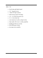
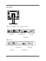
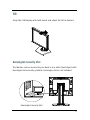
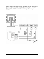
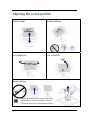
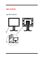
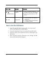
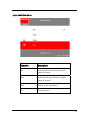
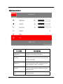
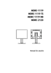
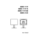
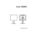
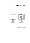
1
MDRC-1119 MDRC-2120 User manual Copyright notice This document is copyrighted. All rights are reserved. Nor this document, nor any part of it, may be reproduced or copied in any form or by any means - graphical, electronic, or mechanical including photocopying, taping or information storage and retrieval systems without written permission of Barco © 2014 Barco N.V. All rights reserved. 2 Table of Contents Table of Contents ....................................................................................... 3 Preface........................................................................................................ 5 Important notice.................................................................................... 5 Environmental information ................................................................... 6 Recommendations for using your display system............................. 10 Unpacking and handling tips .............................................................. 12 Preventing fire and injury ................................................................... 13 Cleaning the display ............................................................................ 13 Shipping/storing the display .............................................................. 14 Explanation of symbols ....................................................................... 15 Introduction .............................................................................................. 16 About the product ............................................................................... 16 Package Overview............................................................................... 18 Installation................................................................................................ 19 Product Overview ................................................................................ 19 Front View....................................................................................... 19 Back View ....................................................................................... 20 Tilt ........................................................................................................ 21 Kensington Security Slot ................................................................ 21 Start Your Installation.......................................................................... 21 Connecting the Display .................................................................. 22 Adjusting the screen position ............................................................. 24 User Controls ............................................................................................ 25 Jog Dial Controls .................................................................................. 25 How to Use the OSD Menus ................................................................ 26 On-Screen Display Menus ................................................................... 27 Appendix .................................................................................................. 45 Troubleshooting................................................................................... 45 Warning Signal .................................................................................... 46 Product Dimensions MDRC-1119/MDRC-1119 TS/MDRC-1119 HB ... 47 Technical specifications MDRC-1119 .................................................. 48 Technical specifications MDRC-1119 TS .............................................. 50 Technical specifications MDRC-1119 HB ............................................. 52 Compatibility Modes MDRC -1119/MDRC-1119 TS/MDRC-1119 HB. 54 Product Dimensions MDRC-2120 ........................................................ 56 3 Technical specifications MDRC-2120 .................................................. 57 Compatibility Modes MDRC-2120 ....................................................... 59 Regulatory Compliance ....................................................................... 60 4 Preface Important notice Notice Although every attempt has been made to achieve technical accuracy in this document, we assume no responsibility for errors that may be found. Our goal is to provide you with the most accurate and usable documentation possible; if you discover errors, please let us know. Barco software products are the property of Barco. They are distributed under copyright by Barco N.V., for use only under the specific terms of a software license agreement between Barco N.V. and the licensee. No other use, duplication, or disclosure of a Barco software product, in any form, is authorized. The specifications of Barco products are subject to change without notice. Trademarks All trademarks and registered trademarks are property of their respective owners. 5 Environmental information Disposal Information The lamps inside the display contain mercury. Do not throw the display in the trash. Dispose of it as required by local ordinances or regulations. This equipment has required the extraction and use of natural resources for its production. It may contain hazardous substances for health and environment. In order to avoid the dissemination of those substances in the environment and to diminish the pressure on natural resources, we encourage you to use the appropriate take-back systems. Those systems will reuse or recycle most of the materials of your end-of-life equipment in a sound way. The crossed-out wheeled bin symbol invites you to use those systems. If you need more information on the collection, reuse and recycling systems, please contact your local or regional waste administrator. You can also contact us for more information on the environmental performances of our products. 6 Safety Instructions General Recommendations Read the safety and operating instructions before operating the display. Retain safety and operating instructions for future reference. Adhere to all warnings on the display and in the operating instructions manual. Follow all instructions for operation and use. Electrical shock Warning- To prevent the risk of fire or shock hazards, do not expose this product to rain or moisture Warning- Please do not open or disassemble the product as this may cause electric shock. Warning- Do not modify this equipment without authorization of the manufacturer. Warning- To avoid risk of electric shock, this equipment must only be connected to a supply mains with protective earth. Warning- Make sure the user not to contact SIP/SOPs and the patient at the same time. Classification: Electrical Shock Protection: Class I. Disconnect Device: Connect / Remove power cord plug directly. Degree of Protection Against Electric Shock: No applied part. Degree of Protection Against Harmful Ingress of Water: Ordinary equipment (IPX0). 7 Degree of Safety in the Presence of Flammable Anesthetic Mixture with Air or with Oxygen or Nitrous Oxide: Not suitable for use in the presence of a flammable anesthetic mixture with air or with oxygen or nitrous oxide. Mode of Operation: Continuous. Intended use This display is an AMLCD display designed for viewing medical X-ray images. This unit should not be used near patients and should be kept outside of 1.83 m perimeter and 2.29 m vertical. The unit is not intended to be used in any life support system and diagnosis. Power connection Power requirements: The display must be powered using a medical approved 12VDC power supply (MDRC-1119, MDRC-1119TS, MDRC-1119HB) or a 24VDC power supply (MDRC-2120). The medical approved DC power supply must be powered by the AC mains voltage. Power requirements: The display must be powered using a medical approved 24 VDC SELV power supply. The medical approved DC power supply must be powered by the AC mains voltage. Power cords Utilize a UL-listed detachable power cord, 3-wire, type SJ or equivalent, 18 AWG min., rated 300 V min., provided with a hospital-grade type plug 5-15P configuration for 120V application, or 6-15P for 240V application. 8 Do not overload wall outlets and extension cords as this may result in fire or electric shock. Mains lead protection (U.S.: Power cord): Power cords should be routed so that they are not likely to be walked upon or pinched by items placed upon or against them, paying particular attention to cords at plugs and receptacles. Use a power cord that matches the voltage of the power outlet, which has been approved and complies with the safety standard of your particular country. External equipment External equipment intended for connection to signal input/output or other connectors, shall comply with relevant UL/ EN/ IEC standard (e.g. UL/EN/IEC 60950 for IT equipment and ANSI/AAMI ES60601-1/EN 60601-1 / IEC 60601 series for medical electrical equipment). In addition, all such combinations – systems – shall comply with the standard IEC 60601-1-1, Safety requirements for medical electrical systems. Equipment not complying with ANSI/AAMI ES60601-1/EN / IEC 60601-1 shall be kept outside the patient environment, as defined in the standard. Equipment not complying with IEC 60601 must be kept outside the patient environment, as defined in the standard as at least 1.5 meters from the patient or the patient support. Any person who connects external equipment to signal input, signal output, or other connectors has formed a system and is therefore responsible for the system to comply with the requirements of IEC 60601-1-1. If in doubt, speak with a qualified technician. In locations where 240V outlets are used, connect this display only on a center-tapped, 240V, single-phase supply. 9 Water and moisture Never expose the display to rain or moisture. Never use the display near water - e.g. near a bathtub, washbasin, swimming pool, kitchen sink, laundry tub or in a wet basement. Ventilation Do not cover or block the ventilation openings in the cover of the set. When installing the display in a cupboard or another closed location, heed the necessary space between the set and the sides of the cupboard. Installation Place the display on a flat, solid and stable surface that can support the weight of at least 3 displays. If you use an unstable cart or stand, the display may fall, causing serious injury to a child or adult, and serious damage to the equipment. Recommendations for using your display system 1. Optimize the lifetime of your display Enabling the Display Power Management System (DPMS) of your display (in the display’s Settings menu) will optimize its lifetime by automatically switching off the backlight when the display is not used for a specified period of time. By default, DPMS is enabled on your display, but it also needs to be activated on your workstation. To do this, go to “Power Options Properties” in the “Control Panel”. Barco recommends setting DPMS activation after 20 minutes of non-usage. 10 2. Use a screen saver to avoid image retention Prolonged operation of an LCD with the same content on the same screen area may result in a form of image retention. You can avoid or significantly reduce the occurrence of this phenomenon by using a screen saver. You can activate a screen saver in the “Display properties” window of your workstation. Barco recommends setting screen saver activation after 5 minutes of non-usage. A good screen saver displays moving content. In case you are working with the same image or an application with static image elements for several hours continuously (so that the screen saver is not activated), change the image content regularly to avoid image retention of the static elements. 3. Understand pixel technology LCD displays use technology based on pixels. As a normal tolerance in the manufacturing of the LCD, a limited number of these pixels may remain either dark or permanently lit, without affecting the performance of the product. To ensure optimal product quality, Barco applies strict selection criteria for its LCD panels. To learn more about LCD technology and missing pixels, consult the dedicated white paper available at www.barco.com/healthcare. 4. Enhance user comfort Every Barco multi-head display system is color matched with the highest specification in the market. Barco recommends keeping color-matched displays together. Furthermore, it is important to use all displays of a multi-head configuration at the same rate to preserve color matching throughout the economic lifetime of the system. 11 5. Maximize Quality Assurance The ‘MediCal QAWeb’ system offers online service for high-grade Quality Assurance, providing maximum confidence and uptime. Learn more and sign up for the free MediCal QAWeb Essential level at www.barco.com/healthcare/qa Unpacking and handling tips The MDRC display is a precision instrument that requires proper care to maintain product operation and adherence to specification. Unpack the display and components carefully, then set up and handle the unit properly to avoid damage to the LCD panel. Use both hands to grasp the display case when lifting it from the shipping carton, but avoid touching the screen. Do not apply pressure to the screen or touch the screen with bare fingers or objects. Pressure can affect image quality. Cosmetics and oils on the skin are both detrimental to the screen and difficult to remove. Allow the display to warm up to room temperature before turning it on. Avoid sudden temperature changes in the environment, as this may cause condensation, which damages the display. Do not set up the display near strong light or heat sources. Do not block the vents on the back of the display or install the display in a built-in enclosure. Blocked vents cause excessive heat to build up inside the display, increasing risk of fire. When installing components, turn off your computer, but leave it plugged into a grounded outlet. Do not remove the back cover or disassemble the display. There are no user-serviceable parts inside. 12 Preventing fire and injury Replace the power supply or cables if damaged. Use only the power source indicated in this guide or listed on the display. Do not plug the power supply into an overloaded AC outlet or extension cord. Overloaded AC outlets and cords can result in electric shock or fire. Do not drop or push objects into the display case. Internal components contain high voltage. Unplug the power cord from the wall outlet during thunderstorms. Do not place magnetic devices, such as motors, near the display. Cleaning the display Observe the following guidelines to maintain display and LCD screen. Use a clean, lint-free, absorbent cotton cloth to clear off any residual glue from removal of the protective film or to remove surface dust. Apply light pressure to remove the dust. Dampen a clean cloth with a small amount of isopropyl alcohol to remove glue or dust if the screen is still not clean. Do not saturate the cloth; otherwise, alcohol may seep into the display case and collect in the enclosure. Use a clean, dry cloth to completely remove the alcohol residue. It is advised to clean the display on weekly basis. Do not use chemically treated dust cloths, acetone, toluene, or harsh solvents on the display case or the screen. They can damage the polarizer and the display case. 13 Do not expose the display to water or excessive moisture. Do not allow water or other stains to stand on the unit. Wipe liquids off immediately to prevent damage to the display case and the screen. Shipping/storing the display Keep the display in its shipping container until installation. Return the display to its original container whenever you need to store the unit, move it to another location, or return it for repair. The packaging supplied by the manufacturer protects the display while it is in transit. See environment specifications for more information. Before returning the display to the container, do the following: 1 Swivel the display panel in landscape mode. 2 Push the panel down to the lowest position. 3 Use the stand lock to anchor the panel. 14 Explanation of symbols DISPOSAL. Do not use household or municipal waste collection services for disposal of electrical and electronic equipment. EU countries require the use of separate recycling collection services. CAUTION. Read the accompanying text carefully for proper operation and maintenance of the display system. DIRECT CURRENT ALTERNATING CURRENT RELATIVE HUMIDITY Storage & transport: 5%~ 90% (No condensation) Operating: 8% ~ 80% TEMPERATURE Storage & transport: -20° to 60° Operating: 0°~35°C ISO 7000-1641. Follow operating instructions or consult instructions for use. 15 Introduction About the product Thank you for choosing Barco. The MDRC series are LCD displays with an active matrix, thin-film transistor (TFT) liquid crystal display (LCD). These products also demonstrate the following outstanding features: MDRC-1119 / MDRC-1119 TS / MDRC-1119 HB Dual Analog and Digital signal. 19” diagonal Screen. 1280x1024 high resolution. Wide Viewing Angle Technology. 31.5 ~ 80 kHz horizontal scan. 56 ~ 75 Hz refresh rate. Auto Adjustment and Re-scaling function. High quality full screen re-scaling capability. Multilingual OSD user controls. VESA DPM power saving. Kensington lock capability 16 MDRC-2120 Dual Analog and Digital signal. 20.1” diagonal Screen. 1600x1200 high resolution. Wide Viewing Angle Technology. 31.5 ~ 93.75 kHz horizontal scan. 59 ~ 61 Hz refresh rate. Auto Adjustment and Re-scaling function. High quality full screen re-scaling capability. Multilingual OSD user controls. VESA DPM power saving. Kensington lock capability 17 Package Overview Power Adapter USA Power Cord VGA Signal Cable 18 EUR Power Cord China Power Cord DVI-D Cable User’s Manual Installation Product Overview Front View 19 Back View MDRC-1119 / MDRC-1119 TS / MDRC-1119 HB USB Ports DC Power-In VGA Input DVI-D Input MDRC-2120 DC Power-In USB Ports 20 VGA Input DVI-D Input Tilt Grasp the LCD Display with both hands and adjust the tilt as desired. Kensington Security Slot The Monitor can be secured to your desk or any other fixed object with Kensington lock security products. Kensington lock is not included. Kensington Security Slot 21 Start Your Installation Connecting the Display Use only the power adapter which are the forming part of each medical device, the power cord, and the video cable shipped with this display. CAUTION: For MDRC-1119 / MDRC-1119 TS: The universal external 12V DC/ 5.0A power adapter (100-240V~, 1.5A, 50-60Hz for power adapter rating) is the BridgePower (BPM060S12F09). For MDRC-2120: The universal external 24V DC/ 2.7A power adapter (100-240V~, 1.5A, 50-60Hz for power adapter rating) is the BridgePower (JMW190KB1200F09). For MDRC-1119 HB: The universal external 12 V DC / 7.0A power adapter (100-240V~, 2.0A, 50-60Hz for power adapter rating) is the BridgePower (JMW190KB1200F09). To setup this display, please refer to the following figure and procedures. 1. Be sure all equipment is turned off. 2. Connect the DC power cord to the power connector; plug one end of the AC power cord into the power adapter, and the other end into an electrical outlet. (1). 3. For a PC with Analog output: Connect the VGA signal cable from display VGA input connector to the 15-pin connector of your host computer and tighten the screws. (2). 4. For a PC with DVI digital output: Connect the DVI signal cable to the connector of the display card in your computer, connect the other side to the DVI-D input port of your display. Tighten the screws (3). 5. Turn on your computer, display and video source. Note: To ensure the LCD Display will work well with your computer, please configure the display mode of your graphics card to make it less 22 than or equal to the native resolution, and make sure the timing of the display mode is compatible with the LCD screen. We have listed the “Compatibility Modes” of this LCD screen in appendices for your reference. 23 Adjusting the screen position Vertical Height Portrait/Landscape Left to Right Pan Front to Back Tilt Remove Monitor Stand may forcefully extend and cause injury Lift Monitor to "Full UP" position in advance Picking up the base or removing the monitor 24 User Controls Jog Dial Controls 25 No./ Icon Control Function - Power Switch - Menu 1. Press the jog dial button for 1 sec to power off to the LCD Display. 2. Swivel jog dial button for OSD menu Jog Dial button LED Power LED 1. Green indicates the display is turned on. 2. Orange indicates the display is in stand-by mode. How to Use the OSD Menus 26 1. Swivel the Jog dial button to pop up the ”on-screen menu” and to scroll among the six Main Menus. 2. Choose the adjustment items by pressing the jog dial button. 3. Adjust the value of the adjustment items by swiveling the jog dial button. 4. After a period of inactivity *(based on a user setting), the OSD menus will automatically disappear. On-Screen Display Menus Main Menu Function Input Selection Description Go to the ‘Input Selection Menu’ while the jog-dial button is pressed. Adjustments Go to the ‘Adjustment Menu’ while the jog-dial button is pressed. 27 Color Go to the ‘Color Menu’ while the jog-dial button is pressed. Geometry* Go to the ‘Geometry Menu’ while the jog-dial button is pressed. Settings Go to the ‘Settings Menu’ while the jog-dial button is pressed. Information Go to the ‘Information Menu’ while the jog-dial button is pressed. Exit 28 Close this menu. Input selection Menu Function DVI Description Select the DVI input while the jog-dial button is pressed. VGA Select the VGA input while the jog-dial button is pressed. Back Go back to the ‘Main Menu’. Exit Close this menu. 29 Adjustments Menu Function Brightness Contrast** Description To adjust the backlight luminance.. To adjust the image contrast (only applicable if VGA is selected). Sharpness** Manual adjustment of the image sharpness (only applicable if VGA is selected) Gamma Go to the ‘Gamma Menu’ while the jog-dial button pressed. Exit 30 Close this menu. Adjustments -> Gamma menu Function Description Native Select the panel original gamma. Gamma 1.8 Select the Dynamic Gamma 1.8. Gamma 2.2 Select the Dynamic Gamma 2.2. Dicom Select the Dicom. User Select the user defined gamma which built by QAWeb Agent tool. Back Go back to the ‘Adjustments Menu’ Exit Close this menu. 31 Color Menu Function Description Native Select the panel original color temperature. Clearbase Set the image color temperature to Clearbase Bluebase Set the image color temperature to Bluebase User Go to the ‘User Menu’ while the jog-dial button pressed. Back 32 Go back to the ‘Adjustments Menu’. Exit Close this menu. Color Menu -> User Menu Function Description Red Turn red gain value manually. Green Turn green gain value manually. Blue Turn blue gain value manually. Back Go back to the ‘Color Menu’. Exit Close the menu. 33 Geometry Menu** Function Auto set Description Adjust the image parameters to obtain a correctly aligned image automatically while the jog-dial button pressed. clock Adjust the internal clock frequency manually. Increase this value to make the image wider, decrease this value to make the image smaller. Phase Adjust the internal clock phase manually. If this setting is not correct, the vertical bands with alternate intensity will be visible. 34 Horizontal position Adjust the image horizontal position manually. Vertical position Adjust the image vertical position manually. Exit Close this menu. 35 Setting Menu Function OSD Setting Description Go to the ‘OSD Settings menu’ while the jog-dial button is pressed. Factory Reset Go to the ‘Factory Reset Menu’ while the jog-dial button is pressed. Language Go to the ‘Language Menu’ while the jog-dial button is pressed. 36 Power Save Go to the ‘Power Save Menu’ while the jog-dial button is pressed. LED Go to the ‘LED Menu’ while the jog-dial button is pressed. Back Go back to the ‘Main Menu’. Exit Close this menu. 37 Settings Menu -> OSD Settings Menu Function Description OSD Timeout Set the OSD timeout value. OSD Horizontal Set the OSD horizontal alignment OSD Vertical Set the OSD vertical alignment OSD Direction Go to the ‘OSD Direction Menu’ while the jog-dial button pressed. 38 Back Go back to the ‘Settings Menu’. Exit Close the menu. Settings Menu -> OSD Settings Menu -> OSD Direction Function Description Landscape Select OSD Landscape. Portrait Select OSD Portrait. Back Go back to the ‘OSD Settings Menu’. Exit Close the menu. 39 Settings Menu -> Factory Reset Menu Function 40 Description Yes Execute the ‘Factory Reset’. No Abort the ‘Factory Reset’. Back Go back to the ‘Settings Menu’. Exit Close the menu. Settings Menu -> Factory Reset Menu Function Description English Execute the ‘Factory Reset’. Français Select 'Français' as the OSD words while the jog-dial button pressed. Deutsch Select 'Deutsch' as the OSD words while the jog-dial button pressed. Español Select 'Español' as the OSD words while thejog-dial button pressed. Italiano Select 'Italiano' as the OSD words while the jog-dial button pressed. Nederlands Select 'Nederlands' as the OSD words while thejog-dial button pressed. 日本語 Select '日本語' as the OSD words while the jog-dial button pressed. 简体中文 Select '简体中文' as the OSD words while the jog-dial button pressed. 繁體中文 Select '繁體中文' as the OSD words while the jog-dial button pressed. 한국 Select '한국' as the OSD words while the jog-dial button pressed. Back Go back to the ‘Settings Menu’. Exit Close the menu. 41 Settings Menu -> Power Save Menu Function 42 Description On Enable the ‘Power Save’ function. Off Disable the ‘Power Save’ function. Back Go back to the ‘Settings Menu’. Exit Close the menu. Settings Menu -> LED Menu Function Description On Enable the LED. Off Disable the LED. Back Go back to the ‘Settings Menu’. Exit Close the menu. 43 Information Menu Function Description FW version Firmware version System hours System run time Backlight run time Backlight run time Back Go back to the ‘Main Menu’. Exit Close the menu. Notes 1:Symbol (*) means only active while VGA is selected. Otherwise, it will be un-selectable with gray color, and the subordinate items are blocked. Note 2: Symbol (**) means only active while VGA is selected. Otherwise, it will be not selectable with gray color. 44 Appendix Troubleshooting If you are experiencing trouble with the LCD display, refer to the following troubleshooting. If the problem persists, please contact your local dealer or our service center. Problem: No image appears on screen. Check that all the I/O and power connectors are correctly and well connected as described in the “Installation” section. Make sure the pins of the connectors are not crooked or broken. Problem: Partial image or incorrectly displayed image. Check to see if the resolution of your computer is higher than that of the LCD Display. Reconfigure the resolution of your computer to make it less than or equal to the native resolution MDRC-1119, MDRC-1119 TS and MDRC-1119 HB (1280 x 1024) MDRC-2120(1600 x1200) Problem: Image has vertical flickering line bars. Use “Clock” to make an adjustment. Check and reconfigure the display mode of the vertical refresh rate of your graphics card to make it compatible with the LCD Display. 45 Problem: Image is unstable and flickering Use “Phase” to make an adjustment. Problem: Image is scrolling Check and make sure the VGA signal cable (or adapter) is well connected. Check and reconfigure the display mode of the vertical refresh rate of your graphics card to make it compatible with the LCD Display. Problem: Vague image (characters and graphics) Use “Clock” to make an adjustment. If this problem still exists, use “Phase” to make an adjustment. Warning Signal Sometimes you may see warning messages for this LCD Display. This means that the LCD Display cannot correctly receive the signal from the computer graphics card. No Signal This message means that the LCD Display has been powered on but it cannot receive any signal from the computer graphics card. Check all the power switches, power cables, and VGA signal cable. Out Of Range This message means that the signal of the computer graphics card is not compatible with the LCD Display. When the signal is not included in the compatibility mode we have listed in the Appendices of this manual, the LCD display will show this message. 46 Product Dimensions MDRC-1119/MDRC-1119 TS/MDRC-1119 HB 47 Technical specifications MDRC-1119 LCD Panel MDRC-1119 Technology TFT Color LCD (VA) Native resolution 1280 x1024 Active screen diagonal 19" (483 mm) Active screen area 376 x 301 mm Pixel Pitch 0.294 x 0.294 Visual Characteristic Maximum luminance 300 cd/m2 DICOM calibrated luminance 180 cd/m2 Image stabilization BLOS (Backlight sensor) Contrast ratio 1300:1 Aspect ratio 5:4 Viewing angle (CR>10) 178°/178° Display LUT 10 bit Response time (G-G) 8 ms Display Functions Gamma, Dicom Colors 16.7 million Connectivity and control Video Input DVI VGA (DB15) USB 48 (1 upstream, 2 downstream) OSD languages English, French, German, Spanish, Italian, Dutch, Simplified Chinese, Traditional Chinese, Korean. Options Protective Cover Yes Touch Screen No Landscape/Portrait Yes Certifications EMC EN 60601-1-2; FCC-B; ICES-001, VCCI, KETI, CCC, BSMI Safety CE EN60601-1; UL ANSI/AAMI ES60601-1, c-UL, CAN/CSA-C22.2 NO. 60601-1, CCC, KETI, PSE, BSMI Mechanical characteristics Display dimensions (W x H x D) 418 x 346 x 70 mm Landscape, w/o pedestal Display weight With Stand : 8.75 kg Without Stand : 5.65 kg Display stand Tilt, height & swivel Mounting VESA 100x100 WARNING: use suitable mounting apparatus to avoid risk of injury. Power requirements System rating Input: 12Vdc/5A External DC Power Supply Input: 90V-264V (50Hz-60Hz), 1.5A Output: 12Vdc/5A For only use power supply BridgePower: BPM060S12F09 Standby Power <1W Power consumption 50 Watts 49 Environmental Operating T (min-max) 0° to 35°C (32° to 95°F) Humidity 8% - 80% (no condensation) Storage & Transport Humidity 5% - 90% (no condensation) Technical specifications MDRC-1119 TS LCD Panel MDRC-1119 TS Technology TFT Color LCD (VA) Native resolution 1280 x1024 Active screen diagonal 19" (483 mm) Active screen area 376 x 301 mm Pixel Pitch 0.294 x 0.294 Visual Characteristic Maximum luminance 300 cd/m2 DICOM calibrated luminance 180 cd/m2 Image stabilization BLOS (Backlight sensor) Contrast ratio 1300:1 Aspect ratio 5:4 Viewing angle (CR>10) 178°/178° Display LUT 10 bit Response time (G-G) 8 ms Display Functions Gamma, Dicom Colors 16.7 million 50 Connectivity and control Video Input DVI VGA (DB15) USB OSD languages (1 upstream, 2 downstream) English, French, German, Spanish, Italian, Dutch, Simplified Chinese, Traditional Chinese, Korean. Options Protective Cover No Touch Screen Yes Landscape/Portrait Yes Certifications EMC EN 60601-1-2; FCC-B; ICES-001, VCCI, KETI, CCC, BSMI Safety CE EN60601-1; UL ANSI/AAMI ES60601-1, c-UL CAN/CSA-C22.2 NO. 60601-1, CCC, KETI, PSE, BSMI Mechanical characteristics Display dimensions (W x H x D) 418 x 346 x 70 mm Landscape, w/o pedestal Display weight With Stand : 9.39 kg Without Stand : 6.29 kg Display stand Tilt, height & swivel Mounting VESA 100x100 WARNING: use suitable mounting apparatus to avoid risk of injury. Power requirements System rating Input: 12Vdc/5A External DC Power Supply Input: 90V-264V (50Hz-60Hz), 1.5A 51 Output: 12Vdc/5A For only use power supply BridgePower: BPM060S12F09 Standby Power <1W Power consumption 50 Watts Environmental Operating T (min-max) 0° to 35°C (32° to 95°F) Humidity 8% - 80% (no condensation) Storage & Transport Humidity 5% - 90% (no condensation) Technical specifications MDRC-1119 HB LCD Panel MDRC-1119 Technology TFT Color LCD (VA) Native resolution 1280 x1024 Active screen diagonal 19" (483 mm) Active screen area 376 x 301 mm Pixel Pitch 0.294 x 0.294 Visual Characteristic Maximum luminance 600 cd/m2 DICOM calibrated luminance 300 cd/m2 Image stabilization BLOS (Backlight sensor) Contrast ratio 2000:1 Aspect ratio 5:4 Viewing angle (CR>10) 178°/178° 52 Display LUT Response time 10 bit (G-G) 8 ms Display Functions Gamma, Dicom Colors 16.7 million Connectivity and control Video Input DVI VGA (DB15) USB OSD languages (1 upstream, 2 downstream) English, French, German, Spanish, Italian, Dutch, Simplified Chinese, Traditional Chinese, Korean. Options Protective Cover No Touch Screen No Landscape/Portrait Yes Certifications EMC EN 60601-1-2; FCC-B; ICES-001, VCCI, KETI, CCC, BSMI Safety CE EN60601-1; UL ANSI/AAMI ES60601-1, c-UL CAN/CSA-C22.2 NO. 60601-1, CCC, KETI, PSE, BSMI Mechanical characteristics Display dimensions (W x H x D) 418 x 346 x 70 mm Landscape, w/o pedestal Display weight With Stand : Without Stand : 7.61 kg 4.42 kg Display stand Tilt, height & swivel Mounting VESA 100x100 53 WARNING: use suitable mounting apparatus to avoid risk of injury. Power requirements System rating Input: 12Vdc/7A External DC Power Supply Input: 90V-264V (50Hz-60Hz), 2.0A Output: 12Vdc/7A For only use power supply BridgePower: JMW190KB1200F09 Standby Power <1W Power consumption 45 Watts Environmental Operating T (min-max) 0° to 35°C (32° to 95°F) Humidity 8% - 80% (no condensation) Storage & Transport Humidity 5% - 90% (no condensation) Operating altitude 3,048m Compatibility Modes MDRC -1119/MDRC-1119 TS/MDRC-1119 HB Standard Resolution Vertical Refresh (Hz) Horizontal Scan (KHz) IBM VGA IBM VGA IBM VGA 640x350 640x480 720x400 70 60 70 31.5 31.5 31.5 54 VESA VGA VESA VGA VESA SVGA VESA SVGA VESA SVGA VESA SVGA 640x480 640x480 800x600 800x600 800x600 800x600 72 75 56 60 72 75 37.9 37.5 35.1 37.9 48.1 46.9 VESA XGA VESA XGA VESA XGA 1024x768 1024x768 1024x768 60 70 75 48.4 56.5 60.0 VESA XGA VESA XGA 1152x870 1152x864 60 75 54.36 68.1 VESA SXGA VESA SXGA 1280x1024 1280x1024 60 75 63.96 79.95 Apple Mac II Apple Mac Apple Mac 640x480 832x624 1024x768 67 75 75 35.0 49.7 60.2 55 Product Dimensions MDRC-2120 56 Technical specifications MDRC-2120 LCD Panel MDRC-2120 Technology TFT Color LCD (IPS) Native resolution 1600 x1200 Active screen diagonal 20.1" (510.54 mm) Active screen area 432 x 331.5 mm Pixel Pitch 0.255 x 0.255 Visual Characteristic Maximum luminance 300 cd/m2 DICOM calibrated luminance 180 cd/m2 Image stabilization BLOS (Backlight sensor) Contrast ratio 800:1 Aspect ratio 4:3 Viewing angle (CR>10) 178°/178° Display LUT 10 bit Response time (G-G) 6 ms Display Functions Gamma, Dicom Colors 16.7 million Connectivity and control Video Input DVI VGA (DB15) USB (1 upstream, 2 downstream) 57 OSD languages English, French, German, Spanish, Italian, Dutch, Simplified Chinese, Traditional Chinese, Korean. Options Protective Cover Yes Touch Screen No Landscape/Portrait Yes Certifications EMC EN 60601-1-2; FCC-B; ICES-001, VCCI, KETI, CCC, BSMI Safety CE EN60601-1; UL ANSI/AAMI ES60601-1, c-UL CAN/CSA-C22.2 NO.60601-1, CCC, KETI, PSE, BSMI Mechanical characteristics Display dimensions (W x H x D) 455 x 354 x 70 mm Landscape, w/o pedestal Display weight With Stand : 9.8 kg Without Stand : 6.0 kg Display stand Tilt, height & swivel Mounting VESA 100 x 100 mm WARNING: use suitable mounting apparatus to avoid risk of injury. Power requirements System rating Input: 24Vdc/2.7A External DC Power Supply Input: 90V-264V (50Hz-60Hz), 1.5A Output: 24Vdc/2.7A For only use power supply BridgePower: BPM060S24F09 Standby Power <1W Power consumption 55 Watts 58 Environmental Operating T (min-max) 0° to 35°C (32° to 95°F) Operating Humidity 8% - 80% (no condensation) Storage & Transport Humidity 5% - 90% (no condensation) Compatibility Modes MDRC-2120 Standard Resolution Vertical Refresh (Hz) Horizontal Scan (KHz) VGA 640x480 60 31.50 SVGA 800x600 60 37.68 XGA 1024x768 60 48.36 1152*870 60 54.36 SXGA 1280*1024 60 63.96 1MP2FH 1280*1024 60 62.50 1024*1280 59 77.78 UXGA 1600*1200 60 75.00 2MP2FH 1600*1200 59 72.81 1200*1600 59 95.84 59 Regulatory Compliance Canada, European Union, United States This display has been tested and found to comply with IEC/EN 60601-1 and IEC 60601-1-2 standards, and is certified to meet medical standard ANSI/AAMI ES60601-1 and CAN/CSA C22.2 No 60601.1(C US Mark) which are related to electrical shock, fire and mechanical hazards only as shown on right UL mark on this page. The medical display, in addition to meeting medical requirements, has been tested and found to comply with the limits for Federal Communications Commission (FCC) Class B computing devices in a typically configured system since many medical offices are located in residential areas. It is the system integrator’s responsibility to test and ensure that the entire system complies with applicable electromagnetic compatibility (EMC) laws. Barco NV has made great efforts to support the medical device industry, in particular, medical device manufacturers and medical device system integrators. We offer state-of-the-art color displays that are compliant with worldwide accepted medical device safety standards, and for the European market, CE-marked displays based on compliance with counsel directive 93/42/EEC—commonly referred to as the Medical Device Directive (MDD). The following summarizes our qualification of these displays as it relates to compliance with the MDD. 60 The European Medical Device Directive requires that the intended use of the device be defined. The intended use of these displays is “to display alphanumeric, graphic, and image data as inputted from any type of medical device.” These displays do not provide a measurement function in any way, and it is the device and systems manufacturer’s responsibility to verify its function in the integrated device or system. The display was classified as required by the MDD according to Annex IX of the directive and the medical device (MEDDEV) guidance available at the time of classification. Because the display uses electrical energy and has no direct patient connections and—by itself—no medical utility, the display is classified according to Rule 12 as an MDD Class I device, component, or accessory. The MDD states that manufacturers of Class I medical devices or accessories shall satisfy the requirements in regard to design and manufacturing controls, that is, the applicable assessment route to be used for CE-marking under the MDD, and it shall carry the CE mark according to Annex XII of the directive, with no notified body annotation. In the opinion of Barco NV registration required to put this device into commerce is the responsibility of the medical device/system manufacturer, and Barco supports this requirement by providing a European Commission (EC) declaration of conformity. If Barco supplies a display to an end user, rather than a device manufacturer, it is the end user’s responsibility to ensure continued compliance with the MDD of the system in which the display is integrated. The supplier will make available on request, circuit diagrams, component part lists, etc. For vigilance reporting as required under Article 10 of the MDD, Barco NV will provide any information requested by competent authority to support any reported incident investigation by such an authority. 61 EU Declaration of Conformity for Medical Application A Declaration of Conformity has been filed for this product. For additional copies of the Declaration of Conformity document, contact Barco NV The MDRC series digital flat-panel display meets the essential health and safety requirements, is in conformity with, and the CE marking has been applied according to the relevant EU Directives listed below, using the relevant section of the following EU standards and other normative documents; EU EMC Directive 89/336/EEC EU Electromagnetic Compatibility Directive EN 60601-1-2 (2001) Collateral standard electromagnetic Medical Electrical Equipment compatibility requirements EN 55011 (Class B) Limits and methods of measurements for radio interference characteristics of industrial, scientific, and medical equipment IEC 61000-3-2 Harmonic emissions IEC 61000-3-3 Voltage fluctuations/flicker emissions IEC 61000-4-2 Electrostatic discharge requirements for industrial process measurement and control equipment IEC 61000-4-3 Radiated electromagnetic field requirements for industrial 62 process measurement and control equipment IEC 61000-4-4 Electrically fast transients for industrial process measurement and control equipment IEC 61000-4-5 Surge requirements IEC 61000-4-11 Voltage variations/dips/interrupts IEC 61000-4-6 Conducted immunity IEC 61000-4-8 Magnetic field immunity Conformance to the Medical Device Directive 93/42/EEC EN 60601-1 Medical Part 1 General requirements for safety Electrical Equipment. U.S. FCC Compliance Statement This device complies with Part 15 of the FCC Rules. Operation is subject to the following two conditions: (1) This device may not cause harmful interference, and (2) this device must accept any interference received, including interference that may cause undesired operation. NOTE: This equipment has been tested and found to comply with the limits for a Class B digital device, pursuant to Part 15 of the FCC Rules. These limits are designed to provide reasonable protection against harmful interference in a residential installation. This equipment generates, uses, and can radiate radio frequency energy and, if not installed and used in accordance with the instruction, may cause harmful interference to radio communications. 63 However, there is no guarantee that interference will not occur in a particular installation. If this equipment does cause harmful interference to radio or television reception, which can be determined by turning the equipment off and on, the user is encouraged to try to correct the interference by one or more of the following measures: Reorient or relocate the receiving antenna. Increase the separation between the equipment and receiver. Connect the equipment into an outlet on a circuit different from that to which the receiver is connected. Consult the dealer or an experienced radio/TV technical for help. CAUTION: Changes or modifications to this equipment not expressly approved by the party responsible for compliance could void the user’s authority to operate the equipment. Other countries Japan VCCI level B Korea KETI level B PRC CCC level B Taiwan BSMI level B 64 65 B4100531-05 January 2014 Barco nv President Kennedypark 35 8500 Kortrijk Belgium www.barco.com