1
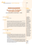
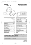
Controller
Wiring Manual
PREFERRED BY PROFESSIONALS WORLD-
Pump Start t Master Valves t Multiple Controllers t Rain Sensors
Soil Moisture Sensors t Remote Control Devices
1. Table of Contents
Page1
2. introduction
Page 2
3. Pump Start Wiring
Page 2
4. Master Valve Wiring
Page 10
5. Multiple Controller Wiring
Page 12
6. Sensor Wiring
Page 14
7. Miscellaneous Wiring
Page 17
8. Index
Page 18
Customer Support Center
6640 S. Bonney Ave. u Tucson, AZ 85706
1-800-RAIN-BIRD u (520) 434-6289 FAX
1
Pump Start Wiring
Wiring a pump start is easily accomplished if you follow a few basic steps. First, be
sure to have a proven wiring diagram available for the particular situation you are
wiring. Next, any Class 1 wiring (above 30 VAC) must be installed by a licensed electrician. Last, if you are not experienced in pump start wiring, find someone who knows
how to install a pump start and learn the basics from them before you attempt to install
one by yourself.
Warning! Any pump start relay wired to an irrigation controller should have
all unused station wires connected to the last used station wire. See Figure
7.
The following diagrams show wiring details for pump start relay and pump motor
starter wiring for various Rain Bird controllers.
Figure 1:
This is a basic pump start wiring diagram for most controllers. This diagram assumes
the Master Valve circuit is being utilized for the pump start circuit.
POWER SOURCE FOR PUMP
MOTOR STARTER HOLDING
COIL (110V OR 24V) AS REQUIRED BY HOLDING COIL
POWER SOURCE TO PUMP
MOTOR STARTER
L1
L2
L3
PUMP
MOTOR
STARTER
HOLDING COIL ON
PUMP MOTOR
STARTER
PUMP
MOTOR
REMOTE PUMP START
RELAY RPS-1
ON REMOTE PUMP START
RELAY RPS-1, CONNECT
THESE TWO WIRES TO
MASTER VALVE WIRE AND
STATION VALVE COMMON
WIRE.
2
Figure 2:
You cannot install more than one controller to a pump start relay. You can however,
install multiple relays to one pump starter. This diagram is for installing two or more
controller relays to one pump starter, and any controller can operate at any time with
any other controller already operating.
Warning!: Be sure to allow for enough hydraulic supply, if multiple controllers
can operate at the same time.
POWER SOURCE FOR PUMP MOTOR STARTER HOLDING COIL
(110V OR 24V) AS REQUIRED BY
HOLDING COIL
POWER SOURCE TO PUMP MOTOR STARTER
L1
L2
L3
PUMP
MOTOR
STARTER
HOLDING COIL ON
PUMP MOTOR
STARTER
PUMP
MOTOR
621970
RELAY FOR RAIN BIRD
CONTROLLERS.
CONTROLLER #1
M.V.
V. COM.
24 VAC
PUMP START
RELAY WIRES
CONTROLLER #2
M.V.
V. COM.
CONTROLLER #3
M.V.
V. COM.
3
Figure 3:
This diagram is for two controllers operating one Master Valve and one pump starter.
POWER SOURCE FOR PUMP
MOTOR STARTER HOLDING
COIL (110V OR 24V) AS REQUIRED BY HOLDING COIL
POWER SOURCE TO PUMP MOTOR
STARTER
L1
L2
L3
PUMP
MOTOR
STARTER
HOLDING COIL ON
PUMP MOTOR
STARTER
PUMP
MOTOR
B
9
A
7
8
CONTROLLER #2
6
5
3
AUX. RELAY 2
2
4
M.V.
V. COM.
1
CONTROLLER #1
B
7
9
M.V.
8
V. COM.
6
AUX. RELAY 1
A
4
5
3
2
1
MASTER VALVE
4
Figure 4:
This diagram details the wiring for three controllers operating one pump starter and
utilizing one Common wire, for all valves on all three controllers.
POWER SOURCE FOR
PUMP MOTOR STARTER
HOLDING COIL (110V OR
24V) AS REQUIRED BY
HOLDING COIL
POWER SOURCE TO
PUMP MOTOR
STARTER
L1
L2
L3
PUMP
MOTOR
STARTER
HOLDING COIL ON
PUMP MOTOR
STARTER
PUMP
MOTOR
CONTROLLER
A
COM
M.V.
14
13
12 11 10 9
8
4
FIELD COMMON
5
CONTROLLER
C
COM M.V.
COM M.V.
“C”
“B”
“A”
AUX.
RELAYS
CONTROLLER
B
7
3
6
2
B
A
B
A
9
8
7
9
8
7
5
6
5
4
6
5
4
1
3
2
1
3
2
1
FOR ALL VALVES
Figure 5:
This wiring diagram shows us the wiring for four controllers wired to one pump starter,
and one Common wire for all valves on all four controllers. If more than one controller
is in operation at the same time, Controller A takes precedence over Controllers B, C
and D; Controller B will take precedence over C and D; Controller C will take precedence over Controller D.
POWER SOURCE FOR
PUMP MOTOR STARTER
HOLDING COIL (110V OR
24V) AS REQUIRED BY
HOLDING COIL
POWER SOURCE TO
PUMP MOTOR
STARTER
L1 L2
L3
PUMP
MOTOR
HOLDING COIL ON
PUMP MOTOR
STARTER
PUMP
MOTOR
CONTROLLER
A
COM
A1
AUX.
RELAYS
B
A
A2
M.V.
14
9
8
7
12 11 10
6
5
4
8
3
2
1
4
7
3
FIELD COMMON
6
6
2
13
9
5
1
CONTROLLER
B
COM
B 14
M.V.
13
12 11 10 9
8
4
7
3
FOR ALL VALVES
6
2
5
1
C
CONTROLLER
C
CONTROLLER
D
COM M.V.
COM M.V.
B
A
D
B
A
8
7
9
8
7
6
5
4
6
5
4
1
3
2
1
3
2
9
Figure 6:
This diagram shows how to wire a pump start relay with a pressure switch. The pressure switch will turn on the pump any time the pressure falls below the preset low
pressure limit. The controller will turn on the pump when a irrigation start is initiated,
whether the pressure switch is active or not.
PRESSURE
SWITCH
PMC
PUMP
MOTOR
STARTER
CONTROLLER
Figure 7:
Any time you wire a pump start relay to a controller, you must wire all unused stations
to the last station with a valve to prevent pump "dead-heading." This diagram shows
wiring details for wiring unused station to the last used station.
VALVE
COMMON
WIRES TO
CONTROLLER
WIRE
CONNECTORS
UNUSED
STATIONS
UNUSED STATION WIRES
CONNECTED TO STATION 4
STATIONS WITH
VALVES
(STATIONS 1-4)
WIRE
CONNECTORS
STATIONS WITH
VALVES
(STATIONS 1-5)
UNUSED STATIONS
(STATIONS 6-8)
7
Figure 8:
This diagram details wiring for operating some valves with a pump and others without
a pump on the same controller. (Many new controller lines have this feature in its programming, this detail is for those controllers which do not.)
CONTROLLER
M.V.
COM.
TO CONTROL STATION X
TO VALVE X
COMMON TO
ALL VALVES
A
B
9
8
6
5
3
2
B
7
4
1
AUXILIARY
RELAY #1
RPS-1
A
9
8
7
6
5
4
3
2
1
MOUNT AUXILIARY RELAYS IN
ANY CONVENIENT
PROTECTED LOCATION,
EXTERNAL OF
CONTROLLER CABINET
AUXILIARY
RELAY #2
2 YELLOW WIRES TO
PUMP STARTER
HOLDING COIL
Figure 8
Operating Instructions:
All stations operating with the pump must be grouped together ahead of control station
"X." When station "X" turns on, the pump is turned off. The pump stays off for all remaining stations in the cycle. When the last station turns off, the pump relay is reset to
operate with the next irrigation start. The pump operates with stations 1 through "X - 1"
and is off with stations X through the last station.
Example: ISC - B + -12 with the pump on for stations #1 through #4 and off with stations #5 through #12. Station #5 is control station X and turns the pump off when the
controller turns on Station #5. When the cycle is complete (all 12 stations have operated), the pump start relay is reset to start the pump at the next irrigation start.
8
Figure 9:
This diagram shows wiring for a pump start relay wired with a rain sensor (Rain
Check) or a soil moisture sensor (Aquamiser).
CONTROLLER STATION OUTPUTS
RAIN SHUTOFF
TB 1
1
3
2
4
5
WIRE
MASTER VALVE
SYSTEM “COMMON”
GROUND WIRE
RPS-1
“COMMON” TO
CONTROL VALVES
IN THE FIELD
FRPS-1
TO PUMP
9
Master Valve Wiring
When wiring multiple controllers to a Master Valve, the controller Master Valve circuits
must be isolated from each other. The following diagrams illustrate how to install relays for multiple controller installations.
Figure 10:
This diagram illustrates the wiring for installing two controllers with one Master Valve.
A Rain Check or Aquamiser device for each controller is also shown. If the Rain
Check or Aquamiser device is not installed, the common wire should be wired to bypass the unit in the diagram.
RAIN
CHECK™
RAIN
CHECK™
#2
#1
CONTROLLER
#2
CONTROLLER
#1
C
O M
M V STATIONS
STATIONS
C
M O
V M
TO VALVES
TO VALVES
M.V. POWER
24 VAC
M.V. COMMON
B
COMMON
TO VALVES
MASTER
VALVE
9
8
6
5
3
2
A
7
4
1
M.V. POWER
M.V. COMMON
COMMON
TO VALVES
10
Figure 11:
This diagram shows the wiring for three controllers sharing one master valve and one
common wire for all valves. This will allow for only one controller to operate at a time.
If more than one controller operates at a time, the common wire will be disconnected
from all field valves on all three controllers.
MASTER VALVE
POWER MAY BE
SUPPLIED FROM
TRANSFORMER IN
NEAREST
CONTROLLER
M.V.
CONTROLLER C
CONTROLLER B
CONTROLLER A
M.V.
COM.
M.V.
COM.
COM.
AUXILIARY
TRANSFORMER
117VAC
AUX.
RELAY A
24VAC
MASTER
VALVE
STA A-1
AUX.
RELAY B
A
B
B
AUX.
RELAY C
A
A
B
9
8
7
9
8
7
9
8
7
6
5
4
6
5
4
6
5
4
3
2
1
3
2
1
3
2
1
STA A-2
STA A-3
STA B-1
11
STA B-2
STA B-3
STA C-1
STA C-2
STA C-3
Multiple Controller Wiring
(Common Wire Isolation)
Wiring multiple controllers on a single project requires the common wire to be separated from each of the controllers. The following diagrams illustrate how to wire these
types of installations.
Figure 12:
This wiring diagram shows how to wire two controllers to one common wire.
OPERATION:
CONTROLLER #1 HAS PRIMARY CONTROL OF THE SYSTEM.
WHEN IT IS ON. THE 2nd. CONTROLLER WILL BE AUTOMATICALLY DISCONNECTED FROM THE FIELD COMMON. IF CONTROLLERS OPERATE AT THE SAME TIME. ONLY VALVES ON
THE #1 CONTROLLER WILL OPERATE.
CONTROLLER #1
PRIMARY UNIT
M.V.
COM.
CONTROLLER #2
SECONDARY
UNIT
COM.
#1 CONT. MASTER VALVE
#1 CONT. COMMON
CO
FIE
LD
MM
ON
MOUNT AUX. RELAY
IN ANY CONVENIENT
LOCATION, ON
EXTERNAL OF
CONTROLLER CABINET.
B
#2 CONT. COMMON
A
7
9
8
6
5
4
3
2
1
ONE VALVE COMMON FOR TWO CONTROLLERS
12
FIELD COMMON
Figure 13:
This diagram shows the wiring detail for the installation of relays to isolate the common wire with three controllers. Controllers should be operated one at a time. If more
than one controller is operated at a time, Controller A takes precedence over Controller B and C; Controller B takes precedence over Controller C.
CONTROLLER A
M.V.
AUX.
RELAY A
CONTROLLER B
COM.
M.V.
A
B
9
8
6
5
AUX.
RELAY B
COM.
COM.
A
B
9
8
7
4
6
5
4
1
3
2
1
7
CONTROLLER C
2
3
STA A-1
TO ALL
VALVES
STA A-2
STA A-3
STA B-1
FIELD
VALVE
COMMON
STA B-2
13
STA B-3
STA C-1
STA C-2
STA C-3
Sensor Wiring
Wiring sensors is quite simple. The following wiring diagrams will assist you
in wiring most common types of sensors.
Figure 14:
This diagram shows how to wire a rain sensor device. (Rain Check)
*
*This splice should be between the controller and the valves, pump start relay or master valve.
14
Figure 15:
This diagram shows the wiring for a soil moisture sensor (Aquamiser).
Irrigation Time Clock
Valve Zones
Power
24V C
Master /
Pump
1
2
4
15
C
1
2
3
4
5
6
7
8
Figure 16:
This diagram illustrates the wiring for a single valve soil moisture sensor.
(lntellisence-100)
White Interrupt Wires
Red
24 VAC
Sensor Probes
Valve Station
Valve Common
16
Remote Control Isolation Wiring
Wiring a remote control device (Remote Bird) to some electromechanical controllers
(RC Series controllers) requires an isolation relay to allow the remote controller to operate properly.
Figure 17:
This diagram illustrates how to wire a remote control device to an electromechanical
controller.
PCC
REMOTE
BIRD
RECEIVER
CONTROLLER
MV
VC
A
B
9
8
7
6
5
4
3
2
1
MASTER
VALVE
17
Index
Item
Page
Common wire
Controller
6, 7, 9, 10, 14, 17, 18,
3, 9, 10, 11, 12, 13,
14, 15, 17
Diagrams:
Multiple controllers to pump start
Multiple controllers to pump start and master valve
Multiple controllers to pump start and single common
Multiple controllers to pump start with priority
Multiple controllers to single master valve and single
common
Multiple controllers to single master valve with multiple sensors
Rain sensor wiring
Remote control wiring (electromechanical controllers)
Single controller to pump start
Single controller to pump start and pressure switch
Single controller to pump start and rain/moisture sensor
Soil moisture wiring (controller interrupt)
Soil moisture wiring (valve interrupt)
Station group pump disconnect
Three controllers to single common
Two controllers to single common
Unused station wiring
Master valve
Pump start relay
Remote control
Sensors
Rain
Soil Moisture
3
4
5
6
11
10
14
17
2
7
9
14
15
8
13
12
7
10, 11
3-9
17
14, 15
14
14, 15
Customer Support Center
6640 S. Bonney Ave.
Tucson, AZ 85706
1-800-RAIN-BIRD
(520) 434-6289 FAX
18