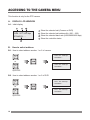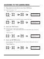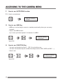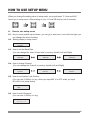
1
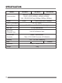
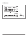
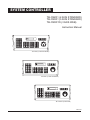
SYSTEM CONTROLLER
TB-CN2R1 (2 AXIS STANDARD)
TB-CN3R1 (3 AXIS STANDARD)
TB-CN3R1W (3 AXIS WEB)
Instruction Manual
TB-CN2R1 (2 AXIS STANDARD)
TB-CN3R1 (3 AXIS STANDARD)
TB-CN3R1W (3 AXIS WEB)
Rev 2.0
CONTENTS
WHAT'S IN THE BOX
WARNING & CAUTION
GENERAL DESCRIPTIONS
A. GENERAL DESCRIPTIONS
B. FEATURES
INSTALLATION
PART NAMES & FUNCTIONS
A. GENERAL DESCRIPTIONS
B. PART NAME & FUNTIONS (REAR SIDE)
C. DRAWING OF CONSOLE DESK
ACCESSING TO THE CAMERA MENU
A. DISPLAY LCD WINDOW
B. How to select address
C. Easy preset save and calls
D. How to use TOUR function
E. How to use PATTERN function
F. How to use AUTOSCAN function
G. How to use ABB key
H. How to use FUNTION key
HOW TO USE SETUP MENU
SPECIFICATION
DIMENSION
What's in the Box ?
1. Controller
2. Junction Box
3. RJ11 8 Pin Modular Cable 1EA
4. Manual
2
2
3
5
5
5
6
8
8
9
9
10
10
10
11
11
11
12
12
12
13
14
15
WARNING & CAUTION
WARNING
TO REDUCE THE RISK OF FIRE OR ELECTRIC SHOCK, DO NOT EXPOSE THIS PRODUCT
TO RAIN OR MOISTURE. DO NOT INSERT ANY METALLIC OBJECT THROUGH THE
VENTILATIONGRILLS OR OTHER OPENINGS ON THE EQUIPMENT.
CAUTION
CAUTION
RISK OF ELECTRIC SHOCK
DO NOT OPEN
CAUTION: TO REDUCE THE RISK OF ELECTRIC SHOCK,
DO NOT REMOVE COVER(OR BACK).
NO USER-SERVICEABLE PARTS INSIDE.
REFER SERVICING TO QUALIFIED SERVICE PERSONNEL.
EXPLANATION OF GRAPHICAL SYMBOLS
The lightning flash with arrowhead symbol, within an equilateral triangle, is
intended to alert the user to the presence of un-insulated "dangerous voltage"
within the product's enclosure that may be of sufficient magnitude to
constitute a risk of electric s h o c k t o p e r s o n s .
The exclamation point within an equilateral triangle is intended to alert the
user to the presence of important operating and maintenance (servicing)
instructions in the literature accompanying the product.
3
FCC COMPLIANCE STATEMENT
INFORMATION TO THE USER : THIS EQUIPMENT HAS BEEN TESTED AND FOUND
TO COMPLY WITH THE LIMITS FOR A CLASS A DIGITAL DEVICE, PURSUANT TO
PART 15 OF THE FCC RULES. THESE LIMITS ARE DESIGNED TO PROVIDE
REASONABLE PROTECTION AGAINST HARMFUL INTERFERENCE WHEN THE
EQUIPMENT IS OPERATED IN A COMMERCIAL ENVIRONMENT. THIS EQUIPMENT
GENERATES, USES, AND CAN RADIATE RADIO FREQUENCY ENERGY AND IF
NOT INSTALLED AND USED IN ACCORDANCE WITH THE INSTRUCTION MANUAL,
MAY CAUSE HARMFUL INTERFERENCE TO RADIO COMMUNICATIONS.
OPERATION OF THIS EQUIPMENT IN A RESIDENTIAL AREA IS LIKELY TO CAUSE
HARMFUL INTERFERENCE IN WHICH CASE THE USER WILL BE REQUIRED TO
CORRECT THE INTERFERENCE AT H I S O W N E X P E N S E .
CAUTION : CHANGES OR MODIFICATIONS NOT EXPRESSLY APPROVED BY THE
PARTY RESPONSIBLE FOR COMPLIANCE COULD VOID THE USER'S AUTHORITY TO
OPERATE THE EQUIPMENT.
CE COMPLIANCE STATEMENT
THIS IS A CLASS A PRODUCT. IN A DOMESTIC ENVIRONMENT THIS PRODUCT MAY
CAUSE RADIO INTERFERENCE IN WHICH CASE THE USER MAY BE REQUIRED TO
TAKE ADEQUATE MEASURES.
4
GENERAL DESCRIPTIONS
A.
GENERAL DESCRIPTIONS
TB-CN2R1, TB-CN3R1(3 AXIS STANDARD) AND TB-CN3R1W(3 AXIS WEB ) are pan/tilt
controller and it allows operator to use the functions easily.
*
This controls camera functions such as pan, tilt, zoom, focus and DVR control.
*
This saves and calls camera preset positions.
*
Activates pre-programed pattern, auto-scan and group tour function keys.
*
The LCD shows display current status as well as provides a menu to set operational
parameters.
*
This controller is designed for desktop operation and interface connectors are located
in the junction box.
B.
FEATURES
*
*
*
*
*
*
*
*
*
*
*
*
*
Recalls up to 255 cameras from one key board.
Multi-protocol supported in each cannel (PELCO-D, P)
Preset position control
Various manual control speed (1~64 steps)
Maximum speed is changed according to zoom ratio.
Recalls programmed guard tours from each dome camera
Recalls programmed auto-scan from selected dome camera
Built in LCD Display with blue screen.
Programmable user preference. (tour, preset, pattern, auto-scan, etc.)
User password and system hold function
Supports DVR Protocol (Need to be modified)
Supports web communication for TX/RX ( TB-CN3R1W only)
Slave Communication to RS232
5
INSTALLATION
1. Jump
2. Junction Box
3. LAN 4. DATA
7. Terminal Block
8. D-SUB Jack (9 pin)
1.
2.
3.
4.
5.
6.
7.
8.
6
lave Setting Jump
Junction Box
LAN Cable Connection
RJ45 Modular Jack (Data Input)
Modular Cable - 8pin
Junction Box to Key Board
RJ45 Modular Jack (Data Output)
Terminal Block
(To PTZ Communication Wire)
D-SUB Connector
(To DVR Communication Port)
5. Cable
6. DATA
INSTALLATION
Open the box and check if below all items are included in the box.
· KEY BOARD
1
· JUNCTION BOX
1
· 8P RJ45 MODULAR CABLE (2mm)
1
CONNECTOR
There is one Connector on the Controller, Which Connector is RJ45 For Master Control.
A.
B.
C.
D.
E.
Connect RJ45 on the rear of controller and DATA on the junction box and plug in DC
12V power to DC jack.
Open the Junction Box cover and set slave interface jumps (LAN,RS232)
Default setting for TB-CN2R1 (2 Axis standard) and TB-CN3R1(3 Axis standard) is by
RS-232 and TB-CB3R1W (3 Axis WEB) is by web.
Connect CAM1(RS485(+), RS485(-)) on Junction Box Terminal and communication
jack on PTZ camera. (Please make sure of polarity)
When you use DVR together, in case of TB-CN3R1W, connect LAN on the junction
box and LAN cable, In case of TB-CN3R1, connect 9 pin D-SUB Jack
Turn on the power and then you will be in starting mode.
7
PART NAME & FUNCTIONS
A.
PART NAME & FUNCTIONS
4
5
6
9 10
32
11 19 1 17 18 25 23
24
29
3
31
2
7
8
12
15 13 16 14
1. LCD Display : Displays numeric input,
system status, function status, general
status, etc
2. Telemetry Joystick : Allows precise
control of Pan/Tilt/Zoom & Moving to
menu
3. 0~9 : Numeric key.
4. MENU : Used for Camera (PTZ Camera)
and DVR Menu adjustment.
5. ESC : closes the current work and goes
to starting mode.
6. DVR : Selects address of DVR
(Up to 255)
7. CLR : Cancels key
8. CAM : Selects address of camera, Mux,
Quad and Matrix Switcher
9. PRST : Saves and calls camera presets
and positions
10. PTRN : Runs to camera pattern key
11. SCAN : Runs to Auto-scan key
12. TOUR : Runs to Tour key
13. ABB : Short key to move to a certain
preset easily
8
30
21
22 20
27
28
26
14. FUNC : Function key
15. ENTER : Enter key (DVR)
16. SEL : Selects Key (DVR and Key Board
setting mode)
17. ZOOM TELE : Camera Zoom Control for Tele
18. ZOOM WIDE : Camera Zoom Control for
Wide
19. FOCUS NEAR : Camera Focus Control for
NEAR
20. FOCUS FAR : Camera Focus Control for FAR
21. IRIS OPEN : Camera IRIR Control for OPEN
22. IRIS CLOSE : Camera IRIS Control for
CLOSE
23. FF : DVR FF Key
24. REW : DVR REW Key
25. PLAY/PAUSE : DVR play and pause key
26. STOP : DVR stop Key
27. FREEZE : Freeze Key
28. DISP/MODE : Select of division mode
29. AUX1,AUX2 : Aux On/Off key (of receiver unit)
30. SEARCH : DVR search Key
31. BACK UP : DVR backup Key
32. LED : TXD, RXD Status LED
PART NAME & FUNCTIONS
B.
PART NAME & FUNCTIONS(REAR SIDE)
1
DATA
1
C.
Data out port (connector to communication and Power)
DRAWING OF CONSOLE DESK
90mm
30mm
30mm
155mm
365mm
9
ACCESSING TO THE CAMERA MENU
This function is only for the PTZ camera.
A.
DISPLAY LCD WINDOW
A-1. Initial display
1
2
3
1
CAM : 001 2400 bps
2
STAND BY.......
3
4
Show the selected unit (Camera or DVR)
Show the selected unit address No. (001 ~ 255)
Show the selected baud rate (2400/4800/9600 bps)
Show the controller status
4
B.
How to select address
B-1. How to select address number 1 or 2 of camera.
CAM : 001 2400 bps
STAND BY....
1
or
CAM
CAM : 002 2400 bps
STAND BY....
2
Up to 255
B-2. How to select address number 1 or 2 of DVR
DVR : 001 2400 bps
1
or
2
Up to 255
10
STAND BY...
DVR
DVR : 002 2400 bps
STAND BY...
ACCESSING TO THE CAMERA MENU
C.
Easy preset save and calls (in case of cam 1/2400 bps)
C-1. How to save preset 1 or 2
- After pushing no.1 or 2, hold PRST for about 2 seconds)
1
or
2
PRST
CAM 001 2400 bps
à 001 Preset Save
Up to 255
- After pushing no.1 or 2, hold PRST shortly, it makes PRST work.
1
D.
or
2
PRST
CAM 001 2400 bps
à 001 Preset
How to use TOUR function
D-1. How to use tour (in case of cam 1/2400 bps)
(You can select 1~ 255, preset position and tour is working when they are stored at
cameras. )
- How to use tour
1
E.
or
2
TOUR
CAM 001 2400 bps
à 001 Tour
How to use PATTERN function
(You can select 1~ 255, preset position and Pattern data is working when they are
stored at cameras. )
- How to Pattern run?
1
or
2
PTRN
CAM 001 2400 bps
à 001 Pattern
11
ACCESSING TO THE CAMERA MENU
F.
How to use AUTOSCAN function
F-1. How to use autoscan
DVR 001 2400 bps
à Scan
SCAN
G.
How to use ABB Key
- ABB key is a short key to move to a certain preset easily when you use many
cameras.
- How to use ABB function.
ex) In case you stored preset 5 of camera 4 in ABB1.
1
CAM 004 2400 bps
à 005 Preset
ABB
Up to 255
H.
How to use FUNCTION Key
- You can use function key from 1~ 255, it is not active now.
- You can use function keys for certain short keys such as DSS, WDR and BLC......)
- How to use
1
or
Up to 255
12
2
FUNC
CAM 001 2400 bps
à 001 Function
HOW TO USE SETUP MENU
When you change the setting value of setup menu, you should enter "5. Save and Exit"
How to go to setup menu : After pushing no. key 11, hold SEL key for over 3 seconds).
1
A.
1
SEL
How to use setup menu
A-1. As you move joystick up and down, you can go to next menu, move left and right, you
can change the value of setting.
A-2. Starting display in setup menu.
1. Band rate
2400 bps
A-3. How to set the Baud Rate
(You can change the value of baud rate by moving Joystick Left and Right)
1. Band rate
2400 bps
1. Band rate
4800 bps
1. Band rate
9600 bps
A-4. How to change Protocol
(You can change the Protocol by moving Joystick Left and Right)
2. Protocol
Tpro201
2. Protocol
Pelco-D
2. Protocol
Pelco-P
A-5. How to use System Lock function
(You can use 0~999 by no. key, when you input 000, it is OFF, when you input
001~999, Lock mode works)
3. System Lock
OFF
A-6. How to enter Password
(You can use 0~999 by no. key)
4. Password
[***] ***
13
SPECIFICATION
MODEL
Communication
Joystic
Power Consumption
Display Type
Key Type
Key board
Connector Type
Junction Box
Connector
Humidity
TB-CN2R1
TB-CN3R1
MASTER : RS485 (2400bps, 4800bps, 9600bps)
SLAVE : RS232 (2400bps, 4800bps, 9600bps)
LAN : (TB-CN3R1W Only) (2400bps, 4800bps, 9600bps)
2-Axis
3-Axis, Zoom IN/OUT available
DC 12V, 110mA
16 x 2 Character LCD, With Blue Backlight
PC Key board Button
RJ45 8 Pin Modular Cable
Master : Terminal Block.
Slave : 9 Pin D-SUB Connector, 8 Pin Modular
10% ~ 70% non Condensing
Web
Dimension
Weight
14
TB-CN3R1W
Available
140(W) x 185(H) x 365(D)
1.2kg
DIMENSIONS
15
Made in Korea
April 2006