1
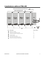
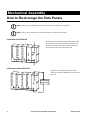
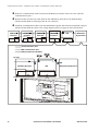
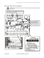
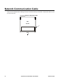
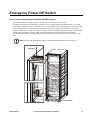
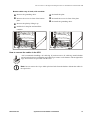
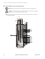
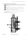
Installation Symmetra® PX UPS, Power Distribution Unit, and XR Battery Enclosure 160 kW 400 V SY160K160H PDUM160H-B SYCFXR9 Contents Safety ................................................................................ 1 IMPORTANT SAFETY INSTRUCTIONS - SAVE THESE INSTRUCTIONS . . . . . . . . . . . . . . . . . . . . . . . . . . . . . .1 Installation Procedure ..................................................... 2 Installations with PDU-XR. . . . . . . . . . . . . . . . . . . . . . . . . . . . . . . . . . .2 Installations without PDU-XR . . . . . . . . . . . . . . . . . . . . . . . . . . . . . . . .3 Mechanical Assembly ..................................................... 4 How to Re-Arrange the Side Panels . . . . . . . . . . . . . . . . . . . . . . . . . .4 Installation with PDU-XR . . . . . . . . . . . . . . . . . . . . . . . . . . . . . . . 4 Installation without PDU-XR . . . . . . . . . . . . . . . . . . . . . . . . . . . . . 4 Installation without PDU-XR and detached UPS . . . . . . . . . . . . . . 5 How to remove and install the side panels . . . . . . . . . . . . . . . . . . 5 How to Prepare the UPS for Cables when the PDU-XR is placed to the left of the UPS. . . . . . . . . . . . . . . . . . . . . . . . . . . . . . . . .6 Communication Cables................................................... 7 Communication Cables in Installations with PDU-XR . . . . . . . . . . . .7 Communication Cables in Installations without PDU-XR . . . . . . . . .9 Maintenance Bypass Panel wiring diagram . . . . . . . . . . . . . . . . 11 Network Communication Cable . . . . . . . . . . . . . . . . . . . . . . . . . . . . .12 Emergency Power Off Switch. . . . . . . . . . . . . . . . . . . . . . . . . . . . . . .13 How to connect the Emergency Power Off (EPO) switch . . . . . . 13 EPO switch wiring diagram . . . . . . . . . . . . . . . . . . . . . . . . . . . . 14 Bonding Wire ................................................................. 15 How to Connect the Bonding Wire . . . . . . . . . . . . . . . . . . . . . . . . . .15 Symmetra PX 160 kW 400 V Installation i Battery Cables ............................................................... 16 How to Install the APC Battery Solution. . . . . . . . . . . . . . . . . . . . . . 16 How to connect the battery cables in the XR Battery Enclosure .16 How to connect the battery cables in the UPS . . . . . . . . . . . . . . .18 Power Cables ................................................................. 19 How to Connect Cables between the UPS and the PDU-XR. . . . . . 19 How to Interconnect and Level the Enclosures. . . . . . . . . . . . . . . . 21 PDU-XR Input and Output Cables . . . . . . . . . . . . . . . . . . . . . . . . . . . 23 How to get access to the cable connection area . . . . . . . . . . . . .23 How to prepare for cables . . . . . . . . . . . . . . . . . . . . . . . . . . . . .24 How to connect the cables in the PDU-XR . . . . . . . . . . . . . . . . .25 How to connect the subfeed breakers . . . . . . . . . . . . . . . . . . . . .28 How to install the power distribution module . . . . . . . . . . . . . . .29 UPS Input and Output Cables in Installations without PDU-XR. . . 30 How to prepare for cables . . . . . . . . . . . . . . . . . . . . . . . . . . . . .30 How to connect the cables in the UPS . . . . . . . . . . . . . . . . . . . .31 Dual mains installation—top or bottom cable entry . . . . . . . . . . .32 Single mains installation—top or bottom cable entry . . . . . . . . .33 Specifications ................................................................ 34 Symmetra PX UPS . . . . . . . . . . . . . . . . . . . . . . . . . . . . . . . . . . . . . . . 34 Required source connections . . . . . . . . . . . . . . . . . . . . . . . . . . .34 Required upstream current protection (dual mains configuration) . . . . . . . . . . . . . . . . . . . . . . . . . . . . .34 Required upstream current protection (single mains configurations) . . . . . . . . . . . . . . . . . . . . . . . . . . .35 Recommended output current protection (single and dual mains) . . . . . . . . . . . . . . . . . . . . . . . . . . . . . . .35 Required wiring for installation . . . . . . . . . . . . . . . . . . . . . . . . .35 Full load heat loss at nominal mains . . . . . . . . . . . . . . . . . . . . . .35 Post-Installation Checklist............................................ 36 ii Symmetra PX 160 kW 400 V Installation Safety IMPORTANT SAFETY INSTRUCTIONS - SAVE THESE INSTRUCTIONS Warning: • ALL safety instructions in the Safety sheet (990-2984) shall be read, understood, and followed when installing the UPS system. Failure to do so could result in equipment damage, serious injury, or death. • The UPS system does not have built-in disconnection devices for AC input/output and DC input. The customer must provide AC input/output over-current protection and AC output disconnect device. • After the UPS has been electrically wired, do not start it. Start-up is commissioned to APC-authorized personnel only. 990-3017A-001 Symmetra PX 160 kW 400 V Installation 1 Installation Procedure Installations with PDU-XR Output External communication wires (web, UPS link etc.) Internal communication wires Power Distribution Module Joining kits* Step Description 2 Page Number Mechanical assembly 4 Connect the communication cables 7 Connect the Network Communication Cable 12 Connect the EPO 13 Connect the battery cables 16 Connect the cables between the UPS and the PDU 20 Interconnect and level the enclosures 23 Connect the input and output cables to the PDU 25 Symmetra PX 160 kW 400 V Installation 990-3017A-001 Installations without PDU-XR External communication wires (web, UPS link etc.) Internal communication wires Joining kits* Step Description Page Number Mechanical assembly 4 Connect the communication cables 9 Connect the Network Communication Cable 12 Connect the EPO 13 Connect the battery cables 16 Interconnect and level the enclosures 23 Connect the UPS input and output cables 32 990-3017A-001 Symmetra PX 160 kW 400 V Installation 3 Mechanical Assembly How to Re-Arrange the Side Panels Note: The type of installation determines the need to re-arrange the side panels. Note: Only systems installed on a raised floor may use bottom cable entry. PDU-XR Remove the side panels on both sides of the UPS and install one of the side panels on the last XR Battery Enclosure in the row, and the other side panel on the open side of the PDU-XR. UPS XR Battery Enclosure XR Battery Enclosure XR Battery Enclosure Installation with PDU-XR 4 UPS Remove one side panel from the UPS, install it on the last XR Battery Enclosure in the row. XR Battery Enclosure XR Battery Enclosure XR Battery Enclosure XR Battery Enclosure Installation without PDU-XR Maintenance Bypass Panel Symmetra PX 160 kW 400 V Installation 990-3017A-001 Mechanical Assembly: How to Re-Arrange the Side Panels Leave the side panels on the UPS. The extra side panels are needed for the open sides of the XR Battery Enclosure(s). UPS XR Battery Enclosure XR Battery Enclosure XR Battery Enclosure XR Battery Enclosure Installation without PDU-XR and detached UPS Maintenance Bypass Panel How to remove and install the side panels To remove the side panels, unlock the side panels with the key (provided). Press down on the lock and pull out and up. 990-3017A-001 To install the side panels, push the panel down and in. Lock the side panels with the key. Symmetra PX 160 kW 400 V Installation 5 How to Prepare the UPS for Cables when the PDU-XR is placed to the left of the UPS If the PDU-XR is on the right side of the UPS (seen from the back) follow the below procedure. Cable relief Back of the UPS Remove the three cable reliefs from the left side and save for step 3. Remove the neutral busbar from the right side of the UPS by loosening the four bolts, and mount the busbar on the left side of the UPS. Mount the cable reliefs from step 1 in the right side. 6 Symmetra PX 160 kW 400 V Installation 990-3017A-001 Communication Cables Communication Cables in Installations with PDU-XR Move the enclosures together so that the communication cables can reach from one enclosure to another. Do not place them close against each other. The extra space is needed to complete the wiring. Plug the battery breaker trip cable into the J3 connector of each XR Battery Enclosure. Cascade the communication cable from each XR Battery Enclosure port 1 to port 2 in the next XR Battery Enclosure. Remove the terminater when necessary. XR Battery Enclosure XR Battery Enclosure XR Battery Enclosure UPS PDU-XR XR communication cable Top view Battery breaker trip cable (EPO) XR Battery Enclosure XR Battery Enclosure J3 XR Battery Enclosure Front Front of the XR Battery Enclosure and back of the PDU-XR 990-3017A-001 Symmetra PX 160 kW 400 V Installation 7 Communication Cables: Communication Cables in Installations with PDU-XR Route the communication cable from last XR Battery Enclosure in the row to the UPS XR Communications port 2. Route the communication cable from the PDU-XR to the UPS XR communications port 1. Route the battery breaker trip cable from the PDU-XR to the EPO/ancillary interface board (0P4123) and plug it into connector J28. Route the three PDU communication cables from the PDU-XR enclosure to the maintenance bypass interface board (0P4194) and plug them into the J7, J3, and J1 connectors. Route the battery breaker trip cable from the last XR Battery Enclosure to the EPO/ancillary interface board (0P4123) and plug it into the J27 connector. XR Battery Enclosure XR Battery Enclosure XR Battery Enclosure UPS PDU-XR XR communication cable PDU communication cable Battery breaker trip cable (EPO) Top view XR Battery Enclosure UPS PDU-XR Front Front of the UPS 8 Symmetra PX 160 kW 400 V Installation 990-3017A-001 Communication Cables in Installations without PDU-XR Move the enclosures together so that the communication cables can reach from one enclosure to another. Do not place them close against each other. The extra space is needed to complete the wiring. Plug the battery breaker trip cable into the J3 connector of each XR Battery Enclosure. Cascade the communication cable from each XR Battery Enclosure port 1 to port 2 in the next XR Battery Enclosure. Remove the terminater when necessary. XR Battery Enclosure Top view XR Battery Enclosure XR Battery Enclosure XR Battery Enclosure UPS Maintenance Bypass Panel XR communication cable Battery breaker trip cable (EPO) XR Battery Enclosure XR Battery Enclosure XR Battery Enclosure XR Battery Enclosure Front Front of the XR Battery Enclosure and back of the PDU-XR 990-3017A-001 Symmetra PX 160 kW 400 V Installation 9 Communication Cables: Communication Cables in Installations without PDU-XR Route the communication cable from the last XR Battery Enclosure in the row to the UPS XR communications port 2. Route the battery breaker trip cable from the last XR Battery Enclosure to the EPO/ancillary interface board (0P4123) and plug it into the J27 connector. Install the communication cables from the Maintenance Bypass Panel into the maintenance bypass interface board (0P4194). Refer to the wiring diagram on the next page for more information. XR Battery Enclosure XR Battery Enclosure XR Battery Enclosure XR Battery Enclosure UPS Maintenance Bypass Panel XR communication cable MBP communication cable Battery breaker trip cable (EPO) Top view XR Battery Enclosure UPS Maintenance Bypass Panel Front Front of the UPS 10 Symmetra PX 160 kW 400 V Installation 990-3017A-001 Communication Cables: Communication Cables in Installations without PDU-XR Maintenance Bypass Panel wiring diagram Warning: Ensure the wires are properly retained and kept away from high-voltage lines and breakers. Make contact closure connections (NO or NC) to monitor dry contatcts. Up to eight connections can be made - four input contacts and four output relays J7, J1, and J3 are only used in systems with PDU-XR. See “Communication Cables in Installations with PDU-XR” on page 7 for more information. Back of the UPS 990-3017A-001 Symmetra PX 160 kW 400 V Installation 11 Network Communication Cable The network communication cable (provided) is located on the top of the UPS. Connect the cable to your local area network. External communication cable UPS Top view Front 12 Symmetra PX 160 kW 400 V Installation 990-3017A-001 Emergency Power Off Switch How to connect the Emergency Power Off (EPO) switch The UPS must be connected to either a dry contact or an external 24 Vdc source. The EPO can be achieved with either a contact closure or application of an external 24 Vac or 24 Vdc from a SELV (Safety Extra Low Voltage) source. It is important to note that hazardous voltage from the mains voltage must be isolated from the contact closure or 24 Vac/24 Vdc. The EPO circuit contact closure, the 24 Vac or 24 Vdc is considered a SELV circuit as defined in EN60950 “Safety of Information Technology Equipment”. SELV circuits are isolated from the mains through a safety isolating transformer, and designed so that under normal conditions, the voltage is limited to 42.4 V peak or 60 Vdc. Note: EPO switch wiring must comply with local and national electrical wiring rules. EPO cable Back of the UPS 990-3017A-001 Symmetra PX 160 kW 400 V Installation 13 Communication Cables: Emergency Power Off Switch EPO switch wiring diagram EPO Wiring Options XR Battery Enclosure PDU-XR Back of the UPS 14 Symmetra PX 160 kW 400 V Installation 990-3017A-001 Bonding Wire How to Connect the Bonding Wire Note: It might be necessary to move some of the bonding wires to fit your system. Connect the two bonding wires between all enclosures in the system. The bonding wires are connected to the PDU-XR and the XR Battery Enclosures. The M8 bolt and star washer are in the kit. M8 PDU-XR UPS XR Battery Enclosure XR Battery Enclosure XR Battery Enclosure Back of the system 990-3017A-001 Symmetra PX 160 kW 400 V Installation 15 Battery Cables How to Install the APC Battery Solution The Symmetra PX 160 kW UPS can monitor up to three APC XR Battery Enclosures in systems with PDU-XR and up to four APC XR Battery Enclosures in systems without PDU-XR. Note: In installations with non-apc batteries, follow the documentation provided with the batteries. How to connect the battery cables in the XR Battery Enclosure Remove the four bolts from the upper cover plate and remove the plate (only in top entry systems). Remove the four bolts from the lower cover plate and remove the plate. Take the cables included in each XR Battery Enclosure. Remove the cable lugs from the cables that will be used to connect the XR Battery Enclosures. For the cables that connect to the UPS, cut off only the cable lug on the end that will be mounted in the XR Battery Enclosure. Back of the XR Battery Enclosure 16 Back of the XR Battery Enclosure with plates removed Symmetra PX 160 kW 400 V Installation 990-3017A-001 Battery Cables: How to Install the APC Battery Solution Mount the BAT+, BAT-, and CT (midpoint) cables between the XR Battery Enclosures. Route the BAT +, BAT-, and CT (midpoint) cables from the XR Battery Enclosure to the UPS through the side, top, or bottom. Mount the PE cable in the XR Battery Enclosure that is farthest from the UPS. Route it through each XR Battery Enclosure and return it to the UPS. BAT+ To the UPS BAT- To the UPS CT (Midpoint) Back of the XR Battery Enclosures 990-3017A-001 Symmetra PX 160 kW 400 V Installation 17 Battery Cables: How to Install the APC Battery Solution How to connect the battery cables in the UPS The cables can be connected through the side, top, or bottom. APC recommends installing a 45º cable lug. If you do not use a 45º cable lug, install a busbar safety bracket between each busbar and cable lug to ensure a safe distance with straight cable lugs. The brackets are provided with the UPS. Note: Do not remove the 12 pcs M10 nylon hex bolts from the busbars. Mount the cables in the open holes. Caution: The power terminal bolt diameter is 10 mm. The required torque value is 26 Nm. Side cable entry. Before running the cables through the side, loosen the three bolts on the cable relief next to the XR Battery Enclosure. Route the battery Cable relief BAT + CT (Midpoint) BAT - cables to the UPS through the holes in the cable relief. BAT CT (Midpoint) Mount the cables BAT + to the busbars according to the labels. Cables from the XR Battery Enclosure Tighten the three bolts on the cable relief. Back of the UPS Top or bottom entry. See “How to prepare for cables” on page 32 for information on how to prepare for cables. Run the cables through top or bottom. Mount the cables to the busbars according to the labels. 18 Symmetra PX 160 kW 400 V Installation 990-3017A-001 Power Cables How to Connect Cables between the UPS and the PDU-XR APC recommends installing a 45º cable lug. If you do not use a 45º cable lug, install a busbar safety bracket between each busbar and cable lug to ensure a safe distance with straight cable lugs. The brackets are provided with the UPS. Note: Do not remove the 12 pcs M10 nylon hex bolts from the busbars. Mount the cables in the open holes. Caution: Ensure clockwise phase rotation and neutral location. The power terminal bolt diameter is 10 mm. The required torque value is 26 Nm. 990-3017A-001 Symmetra PX 160 kW 400 V Installation 19 Power Cables: How to Connect Cables between the UPS and the PDU-XR Before running the cables, loosen the three bolts on each cable relief next to the PDU. Route the cables to the UPS through the holes in the cable relief on the side of the enclosure starting from the bottom with the bypass L3 and then working your way up. Lay the cables neatly to minimize cable build-up. Do not tie the cables up. Mount the cables to the busbars according to the labels. Tighten the three bolts on each cable relief. Cable relief Neutral Mains L1 Mains L2 Mains L3 BAT + CT (Midpoint) BAT - Cables from the PDU-XR Mains: Neutral L1 L2 L3 BAT + CT (Midpoint) BAT Output: Neutral L1 L2 L3 Bypass: Neutral L1 L2 L3 BAT: Neutral Output L1 Output L2 Output L3 Neutral Bypass L1 Bypass L2 Bypass L3 Back of the UPS Side view of the UPS 20 Symmetra PX 160 kW 400 V Installation 990-3017A-001 How to Interconnect and Level the Enclosures Warning: The system must be installed on a level floor. The leveling feet will stabilize the enclosure, but will not account for a badly sloped floor. Note: The communication and power cables cannot be installed once the enclosures are installed side by side. Follow the procedure under “Installation Procedure” on page 2. Align the enclosures. Connect the exterior joining brackets (provided) to secure the enclosures together. M12 M10 XR Battery Enclosure UPS M10 UPS M12 M12 XR Battery Enclosure M12 PDU-XR XR Battery Enclosure Front M8 990-3017A-001 M8 Symmetra PX 160 kW 400 V Installation 21 Power Cables: How to Interconnect and Level the Enclosures Use a screw driver to lower the leveling feet at the front of the enclosure. 22 Warning: Do not move the enclosure after the leveling feet have been lowered. Symmetra PX 160 kW 400 V Installation 990-3017A-001 Power Cables: PDU-XR Input and Output Cables PDU-XR Input and Output Cables How to get access to the cable connection area Open the inside door at the front of the PDU-XR. Remove the three blanking panels. Remove the two bolts at the bottom of the cable channel and remove the cable channel. Front of the PDU-XR Front of the PDU-XR with the bypass panel door open 990-3017A-001 Symmetra PX 160 kW 400 V Installation 23 Power Cables: PDU-XR Input and Output Cables How to prepare for cables Top cable entry without or with conduits. Remove the connection plate. Go to step 2 if conduits needs to be intalled. Drill holes in the plate for conduits. Re-install the plate with the conduits installed. Bottom, front cable entry without conduits. Loosen the bolts and remove the plate by lifting it up and to the right. Bottom, front cable entry with conduits. Remove the bolts. Remove the plate by lifting it up and to the right. Drill holes in the plate for cables. Re-install the plate with the conduits installed. 24 Symmetra PX 160 kW 400 V Installation 990-3017A-001 Power Cables: PDU-XR Input and Output Cables How to connect the cables in the PDU-XR Caution: Ensure clockwise phase rotation and neutral location of the power terminal bolt. The required torque value is 62 Nm. Note: The neutral wire from the AC mains input and AC bypass input is hardwired in the UPS, do not install a jumper between the two neutral connections in single mains installations. Single mains installation. Route the cables from the top or bottom. Use the bypass terminals for mains connection in bottom entry systems. In top entry systems, secure the cables to the cable tray using cable ties with a minimum loop tensile of 80 kg. . Mains Neutral Cable ties Top cable entry L1 L2 L3 Bypass L2 L3 Neutral For top cable entry For bottom cable entry Bottom cable entry L1 990-3017A-001 Front of the PDU-XR Symmetra PX 160 kW 400 V Installation 25 Power Cables: PDU-XR Input and Output Cables Dual mains top or bottom entry. Remove the three busbars. Route the cables through the top or bottom. In top cable systems, secure the cables to the cable tray using cable ties with a minimum loop tensile of 80 kg. Top cable entry Mains Cable ties Neutral L1 L2 L3 L2 L3 Neutral L1 Front of the PDU-XR 26 Symmetra PX 160 kW 400 V Installation Bypass 990-3017A-001 Power Cables: PDU-XR Input and Output Cables Bottom cable entry Mains Neutral L1 L2 L3 L2 L3 Neutral L1 Front of the PDU-XR 990-3017A-001 Bypass Symmetra PX 160 kW 400 V Installation 27 How to connect the subfeed breakers Each subfeed breaker is rated for a maximum of 160 A. Re-install the three blanking panels. Re-install the cable channel. Mount the cables to the subfeed breakers (cables are not supplied). Front of the PDU-XR Front of the PDU-XR 28 Symmetra PX 160 kW 400 V Installation 990-3017A-001 Power Cables: PDU-XR Input and Output Cables How to install the power distribution module Remove the left top plate. Install the power distribution module by sliding the module into the enclosure and securing the latch to lock the module into place. Route the power cables through the top. Front of the PDU-XR 990-3017A-001 Symmetra PX 160 kW 400 V Installation 29 Power Cables: UPS Input and Output Cables in Installations without PDU-XR UPS Input and Output Cables in Installations without PDU-XR How to prepare for cables Top cable entry in the back without conduits. Remove the brush slot plate and the solid Re-install the brush slot plate. plate. Top cable entry in the back with conduits. Remove the brush slot plate and the solid Drill as many holes as necessary in the solid plate. plate and install the conduits. Re-install the plate. Bottom cable entry in the back without conduits. Remove the grounding cable. Remove the screws in front of the bottom plate. Remove the plate by lifting it up. 30 Symmetra PX 160 kW 400 V Installation 990-3017A-001 Power Cables: UPS Input and Output Cables in Installations without PDU-XR Bottom cable entry in back, with conduits. Remove the grounding cable. Re-install the plate. Remove the screws in front of the bottom Re-install the screws in front of the plate plate. Re-install the grounding cable. Remove the plate by lifting it up. Drill holes in the plate and install the conduits. How to connect the cables in the UPS APC recommends installing a 45º cable lug. If you do not use a 45º cable lug, install a busbar safety bracket between each busbar and cable lug to ensure a safe distance with straight cable lugs. The brackets are provided with the UPS. Note: Do not remove the 12 pcs M10 nylon hex bolts from the busbars. Mount the cables in the open holes. 990-3017A-001 Symmetra PX 160 kW 400 V Installation 31 Power Cables: UPS Input and Output Cables in Installations without PDU-XR Dual mains installation—top or bottom cable entry Note: Install the PE cable in the UPS according to the symbol on the grounding rail. Caution: Ensure clockwise phase rotation and neutral location. The power terminal bolt diameter is 10 mm. The required torque value is 26 Nm. Route the cables through top or bottom of the enclosure, and mount the cables to the busbars according to the labels. PE Bypass Output Mains Neutral Mains L1 Mains L2 Mains L3 PE Neutral Output L1 Output L2 Output L3 Neutral Bypass L1 Bypass L2 Bypass L3 Back of the UPS 32 Symmetra PX 160 kW 400 V Installation 990-3017A-001 Power Cables: UPS Input and Output Cables in Installations without PDU-XR Single mains installation—top or bottom cable entry Note: As the neutral from AC mains input and AC bypass input is hardwired internally in the UPS, it is not necessary to install a jumper between the two neutral connections in single mains installations. Note: Install the PE cable in the UPS according to the symbol on the grounding rail. Caution: Ensure clockwise phase rotation and neutral location. The power terminal bolt diameter is 10 mm. The required torque value is 26 Nm. Run the cables through top or bottom of the enclosure and mount the cables to the busbars according to the labels. Install the three cables (0W3617) included with the unit. PE Output Mains Neutral Mains L1 Mains L2 Mains L3 PE Neutral Bypass L1 Bypass L2 Bypass L3 Back of the UPS 990-3017A-001 Symmetra PX 160 kW 400 V Installation 33 Specifications Symmetra PX UPS Caution: All electrical power and power control wiring must be installed by a qualified electrician, and must comply with local and national regulations for maximum power rating. Note: All current values are based on 160 kW maximum configuration of the UPS. Input 380 V 400 V 415 V Nominal input current (A) 256 243 234 Maximum input current (continuous, at 340 V mains voltage) (A)290 290 290 Maximum bypass current (continuous, at nominal load) (A) 243 231 223 Input frequency (Hz) 50/60 50/60 50/60 Output 380 V 400 V 415 V Nominal output current (A) 243 231 223 Neutral output current (with 100% switch mode load) (A) 421 400 386 Maximum overload current (in bypass at 125% overload) (A) 304 289 279 Output frequency (on line, in bypass) Synchronized to Input Output frequency (on battery) (Hz) 50/60 50/60 50/60 Maximum short circuit withstand level (kA) 30 30 30 Overcurrent device and disconnect switch for external safety DC bus voltage (nominal) (V) 2 x 192 DC voltage rating of the battery supply breaker (VDC) 250 Maximum available battery supply fault current (kA) 10 Required source connections • Required mains supply is L1, L2, L3, N, and PE. Contact APC for information about other configurations • Ensure a clockwise voltage phase rotation (L1, L2, L3 or RST) Required upstream current protection (dual mains configuration) • Mains input: 315 A gL type fuse • Bypass input: 250 A gL type fuse 34 Symmetra PX 160 kW 400 V Installation 990-3017A-001 Specifications: Symmetra PX UPS Required upstream current protection (single mains configurations) • Mains input: 315 A gL type fuse Recommended output current protection (single and dual mains) • 250 A gL type fuse or a 250 A 3-pole AC circuit breaker Required wiring for installation • Input and output neutral wires must be rated for 173% of phase load if feeding switch mode power supply loads without input power factor corrections • Copper wiring must be used for input/output wiring Full load heat loss at nominal mains • Full load heat loss at nominal mains: 8,38 kW (28619.2 BTU/hr) Warning: This is a Class A UPS product. In a domestic environment, this product may cause radio interference, in which case, the user may be required to take additional measures. 990-3017A-001 Symmetra PX 160 kW 400 V Installation 35 Post-Installation Checklist 36 If XR Battery Enclosure are installed make sure that all DC breakers are in the OFF position and that both 300 A fuses are removed from the XR Battery Enclosures. Check that the power wiring is torqued to: UPS 230 lbf in/26 Nm, PDU-XR 549 lbf in/62 Nm, and XR Battery Enclosure 274 lbf in/31 Nm. Verify clockwise phase-rotation (L1, L2, L3) and make sure a neutral connection is present. Leave a wiring diagram on site for service personnel. Re-install all wiring access panels on the UPS. Re-mount the doors on all enclosures and connect the ground cables between the front doors and the frames. For any optional equipment, refer to product-specific manuals. Symmetra PX 160 kW 400 V Installation 990-3017A-001 APC Worldwide Customer Support Customer support for this or any other APC product is available at no charge in any of the following ways: • Visit the APC Web site to access documents in the APC Knowledge Base and to submit customer support requests. – www.apc.com (Corporate Headquarters) Connect to localized APC Web sites for specific countries, each of which provides customer support information. – www.apc.com/support/ Global support searching APC Knowledge Base and using e-support. • Contact an APC Customer Support center by telephone or e-mail. – Regional centers Direct InfraStruXure Customer Support Line (1)(877)537-0607 (toll free) APC headquarters U.S., (1)(800)800-4272 (toll free) Canada Latin America (1)(401)789-5735 (USA) Europe, Middle East, Africa (353)(91)702000 (Ireland) Western Europe (inc. Scandinavia) +800 0272 0272 Japan (0) 36402-2001 Australia, New Zealand, (61) (2) 9955 9366 (Australia) South Pacific area – Local, country-specific centers: go to www.apc.com/support/contact for contact information. Contact the APC representative or other distributor from whom you purchased your APC product for information on how to obtain local customer support. Entire contents copyright 2007 American Power Conversion Corporation. All rights reserved. Reproduction in whole or in part without permission is prohibited. APC, the APC logo, and TRADEMARK NAMES are trademarks of American Power Conversion Corporation. All other trademarks, product names, and corporate names are the property of their respective owners and are used for informational purposes only. 990-3017A-001 *990-3017A-001* 10/2007