1
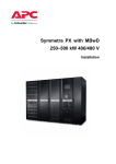
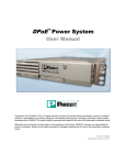
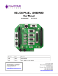
Symmetra PX 100 kW 208 V
Optional Modular PDU
(600:208 V, 480:208 V,
208:208 V, 208 V Transformerless)
Installation
Table of Contents
IMPORTANT SAFETY INSTRUCTIONS – SAVE THESE
INSTRUCTIONS................................................................................................................ 1
Specifications ................................................................................................................... 2
Specifications for Installations without PDU........................................................
AC Input .....................................................................................................................
AC Output ..................................................................................................................
Recommended Current Rating of Feeder Circuit Breakers ........................................
Recommended Conductor Sizes per Phase/Neutral ..................................................
Recommended Bolt and Lug Sizes ............................................................................
Full Load Heat Loss at Nominal Mains ......................................................................
2
2
2
3
3
4
4
Specifications for Installations with PDU.............................................................. 4
AC Input ..................................................................................................................... 4
AC Output .................................................................................................................. 5
PDU Subfeed Circuit breaker Trip Currents Merlin Gerin NSJ400 - STR23SP
Electronic Trip Unit1 ...................................................................................................
Recommended Current Rating of Input Circuit Breaker ............................................
Inrush Currents .........................................................................................................
Recommended Conductor Sizes ...............................................................................
Full Load Heat Loss at Nominal Mains ......................................................................
5
5
5
6
7
Batteries ......................................................................................................................... 7
Installation Procedure.................................................................................................. 8
Installations without PDU .......................................................................................... 8
Installations with PDU with Transformer ............................................................... 9
Single Utility System.................................................................................................. 9
Dual Utility System ....................................................................................................10
Installations with PDU without Transformer.........................................................11
Single Utility System..................................................................................................11
Dual Utility System ....................................................................................................12
Mechanical Assembly ..................................................................................................13
Re-arrange the Side Panels.......................................................................................13
Remove the Side Panels ............................................................................................13
Install the Side Panels ................................................................................................14
Install the Internal Conductors for Bottom Entry Systems in
Installations with PDU without Transformer.........................................................14
Perform Equipotential Bonding................................................................................15
Interconnect and Level the Enclosures .................................................................15
990–3659C-001
Symmetra PX 100 kW 208 V
i
Prepare for Cables .........................................................................................................17
Installations without PDU ..........................................................................................17
Top Cable Entry .........................................................................................................18
Bottom Cable Entry ...................................................................................................18
Installations with PDU with Transformer ...............................................................19
Top Cable Entry .........................................................................................................20
Bottom Cable Entry ...................................................................................................21
Installations with PDU without Transformer.........................................................22
Top Cable Entry .........................................................................................................23
Bottom Cable Entry ...................................................................................................24
Power Cables ....................................................................................................................26
Connect Power Conductors in Installations without PDU ................................27
Connect Power Conductors in Installations with PDU with
Transformer ...................................................................................................................28
Connect Power Conductors in Installations with PDU without
Transformer — Top Cable Entry...............................................................................30
Connect Power Conductors in Installations with PDU without
Transformer — Bottom Cable Entry........................................................................31
Connect Power Conductors between the UPS and the PDU (Applicable
to all Systems with PDU)............................................................................................32
Connect Output Cables to the Subfeed Breaker ........................................................33
Install and Connect Output Cables to the Power Distribution Module .......................34
Battery Cables ..................................................................................................................35
Install the APC Battery Solution ..............................................................................35
Connect the Battery Cables between the XR Battery Enclosures ..............................35
Connect the Battery Cables to the UPS .....................................................................37
Emergency Power Off (EPO) Switch ....................................................................39
EPO switch wiring diagram .......................................................................................40
Communication Wires .................................................................................................41
Connect Network Communication Wire.................................................................41
Connect Communication Wires in Installations without PDU .........................42
Maintenance Bypass Panel Interface .........................................................................43
Connect Communication Wires in Installations with PDU ...............................44
Install Seismic Option ..................................................................................................45
Replace the Side Panel Lock ....................................................................................45
Install the Rear Anchoring Brackets.......................................................................48
ii
Symmetra PX 100 kW 208 V
990–3659C-001
Install the Front Anchoring Bracket........................................................................49
Install the Top Assembly Bracket ............................................................................49
Install the Door Hinge Lock.......................................................................................50
Install the Battery Locks ............................................................................................51
990–3659C-001
Symmetra PX 100 kW 208 V
iii
iv
Symmetra PX 100 kW 208 V
990–3659C-001
IMPORTANT SAFETY INSTRUCTIONS –
SAVE THESE INSTRUCTIONS
WARNING: ALL safety instructions in the Safety sheet (990-2984) must be read,
understood, and followed when installing the UPS system. Failure to do so could result
in equipment damage, serious injury, or death.
WARNING: The UPS system does not have built-in disconnection devices for AC
input/output and DC input. The customer must provide AC input/output over-current
protection and an AC output disconnect device.
WARNING: After the UPS has been electrically wired, do not start it. Start-up is
commissioned to APC-authorized personnel only.
WARNING: The Sidecar (model PDPM100SC) is required for underfloor wiring into
the PDU when the PDU contains a transformer. The Sidecar does not contain a switch
or circuit breaker, so a readily accessible disconnect device shall be incorporated
external to the equipment.
WARNING: For remote XR Battery Enclosures, the lenght of the signal and power
cables must not exceed 200 m, on the cable that connects the XR Battery Enclosure to
the UPS. For power cables between 50 and 200 m, the voltage drop must be taken into
account when the cable size is chosen. All electrical power and power control wiring
must be installed by a qualified electrician, and must comply with local and national
regulations for maximum power rating.
990–3659C-001
Symmetra PX 100 kW 208 V
1
Specifications
Caution: All electrical power and power control wiring must be installed by a qualified
electrician, and must comply with local and national regulations for maximum power rating.
Note: All current values are based on a 100 kW maximum configuration of the UPS.
Specifications for Installations without PDU
AC Input
208 V UPS only
Connection type, single feed
4-wire (3PH + N + G)
Connection type, dual feed
Mains input: 3 wire (3PH+G), Bypass Mains input:
4-wire (3PH + N + G)
Nom. input frequency (Hz)1
60
Nom. input current (A)2
302
(A)3
332
(A)4
360
Max. input current
Input current limit
Nom. bypass input current (A)
278
Maximum available fault current (kA)5
30
1
Input frequency (Hz) 40-70 with 10Hz/sec slewrate.
Input current based on nominal voltage and rated load, batteries fully charged.
3 Input current based on full battery recharg, nominal voltage and rated load.
4 Current limitation through electronic current limiting is based on full rated load and limited battery recharge from
-10% to -15% input voltage.
5 The maximum available fault current was not evaluated by Underwriters Laboratories.
2
AC Output
208 V UPS only
Connection type
4-wire (3PH+ N + G) or 3 wire (3PH+G)
Nominal output current (A)
278
2
Symmetra PX 100 kW 208 V
990–3659C-001
Recommended Current Rating of Feeder Circuit Breakers
Caution: To reduce the risk of fire, connect only to a circuit provided with (see below)
amperes maximum branch circuit overcurrent protection in accordance with the National
Electric Code, NSI/NFPA 70.
208 V UPS only
Standard rated (80%)
100% rated
Mains input (A)
450
400
Bypass input (A)
450
400
Battery (A)
300
300
Output (A)
350
300
Recommended Conductor Sizes per Phase/Neutral
Caution: All wiring must comply with all applicable national and/or local electrical codes.
Conductor sizing in this manual is based on Table 310-16 of the National Electrical Code (NEC) with
the following assertions.
• 90◦C conductors (THHN) for 75◦C termination
• 3 current carrying cable
• An ambient temperature of 30◦C
• Use only copper conductors
If the ambient room temperature is greater than 30◦C, larger conductors are to be selected in accordance
with the correction factors of the NEC.
Equipment Grounding Conductors (EGC) are sized in accordance with NEC Article 250-122 and Table
250-122.
Grounding Electrode Conductors (GEC) are sized in accordance with NEC Article 250-66 and Table
250-66.
The conductor sizes are recommendations for maximum configurations. Even if the load is less than the
maximum rating, it is wise to plan for future load increases. If the system is operated at a lower load
than its rating and it is desired to supply the system with a lower rated breaker and smaller conductors,
conductor ampacities are to be selected in accordance with the NEC.
208 V UPS only
Standard rated (80%)
100% rated
Mains input
2 x 4/0 AWG
500 kcmil
Bypass input
2 x 4/0 AWG
500 kcmil
Battery
300 kcmil
300 kcmil
Output
500 kcmil
300 kcmil
Equipment Grounding Conductor
3 AWG
3 AWG
990–3659C-001
Symmetra PX 100 kW 208 V
3
Recommended Bolt and Lug Sizes
Cable
Terminal Bolt
Diameter
Cable Lug Type
Crimping tool CT-720
Crimping Die:
80% rated
100% rated
80% rated
100% rated
Mains input
M10
LCA4/0-12H-X
LCA500-12H-6
CD-720-3
CD-720-7
Bypass input
M10
LCA4/0-12H-X
LCA500-12H-6
CD-720-3
CD-720-7
Battery 1
M10
LCA300-12H-X
LCA300-12H-X
CD-720-4
CD-720-4
Battery 2
M10
LCA300-12H-X
LCA300-12H-X
CD-720-4
CD-720-4
Output
M10
LCA500-12H-X
LCA300-12H-X
CD-720-7
CD-720-4
Full Load Heat Loss at Nominal Mains
Full load heat loss at nominal mains: 8.1 kW (27656.8 Btu)
WARNING: This is a Class A UPS product. In a domestic environment, this product
may cause radio interference, in which case, the user may be required to take additional
measures.
Specifications for Installations with PDU
AC Input
208 V : 208 V
480 V : 208 V
600 V : 208 V
No transformer
Connection type
3PH+ G+GEC
3PH+ N+G
Nom. input
frequency (Hz)
57-63
40-70
Nom. input current
(A)1
307
133
106
302
Max. input current
(A)2
337
146
117
332
Input current limit
(A)3
366
165
127
360
Nom. bypass input
current (A)
282
122
98
278
Maximum available
fault current (kA)4
65
65
25
30
1
Input current based on nominal voltage and rated load, batteries fully charged
Input current based on full battery recharg, nominal voltage and rated load
3 Current limitation through electronic current limiting is based on full rated load and limited battery recharge from
-10% to -15% input voltage.
4 The maximum available fault current was not evaluated by Underwriters Laboratories.
2
4
Symmetra PX 100 kW 208 V
990–3659C-001
AC Output
208 V : 208 V
480 V : 208 V
600 V : 208 V
No transformer
278
278
Connection type
4-wire (3PH + N + G) or 3 wire (3PH+G)
Output voltage
3 x 208/120 V
Nominal output
current (A)
278
Power Distribution
Modules (A) (not
included)
20 A, 30 A, 40 A, 50 A, 60 A
Subfeed
278 A maximum (included) see following table
278
PDU Subfeed Circuit breaker Trip Currents Merlin Gerin NSJ400 STR23SP Electronic Trip Unit1
Io Setting
Ir Setting
1
0.98
0.95
0.93
0.90
0.88
0.85
0.9
0.8
288
0.8
297.63
288
281.6
272
256
0.7
280
274.4
266
260.4
252
246.4
238
224
0.63
252
247
239.4
234.4
226.8
221.8
214.2
201.6
0.5
200
196
190
186
180
176
170
160
1
400 A frame, 100% rated @400 A
Long-time (LT) overload protection = In x Io x Ir- Example: 400 x 0.5 x
0.8=160 A. See NEC-2008 Art. 240.6 (C) for additional information.
3 Factory default: 400 x0.93 x 0.8 = 297.6 A or ˜ 300 A. The maximum
Subfeed Output Loading must not be greater than 278 A/phase.
2
Recommended Current Rating of Input Circuit Breaker
208 V : 208 V
480 V : 208 V
600 V : 208 V
No transformer
225
175
450
Standard rated*
Mains input (A)
500
* Standard circuit breakers are rated to carry 80% of their current rating continuously.
Inrush Currents
The supply overcurrent protective device must be able to handle the below transformer inrush currents.
Inrush current (A)
990–3659C-001
208 V : 208 V
480 V : 208 V
600 V : 208 V
4500
2000
1500
Symmetra PX 100 kW 208 V
5
Recommended Conductor Sizes
Caution: All wiring must comply with all applicable national and/or local electrical codes.
Conductor sizing in this manual is based on Table 310-16 of the 2008 National Electrical Code (NEC)
with the following assertions:
• 90◦C conductors (THHN) for 75◦C termination
• 3 Current Carrying Conductors
• An ambient temperature of 30◦C
If the ambient room temperature is greater than 30◦C, larger conductors are to be selected in accordance
with the correction factors of the NEC.
Equipment Grounding Conductors (EGC) are sized in accordance with NEC Article 250-122 and Table
250-122.
Grounding Electrode Conductors (GEC) are sized in accordance with NEC Article 250-66 and Table
250-66.
The conductor sizes are recommendations for maximum configurations. Even if the load is less than the
maximum rating, it is wise to plan for future load increases. If the system is operated at a lower load
than its rating and it is desired to supply the system with a lower rated breaker and smaller conductors,
conductor ampacities are to be selected in accordance with the NEC. The transformer inrush must be taken
into account when sizing conductors.
208 V : 208 V
480 V : 208 V
600 V : 208 V
No transformer
Cu
(2) 4/0
4/0
2/0
(2) 4/0
Al
(2) 300 kcmil
300 kcmil
4/0
(2) 300 kcmil
Grounding
Electrode
Conductor
(GEC)
Cu
2 AWG
Al
1/0
Equipment
Grounding
Conductor
(EGC)
Cu
2 AWG
4 AWG
6 AWG
2 AWG
Al
1/0
2 AWG
4 AWG
1/0
Output
Supplied with Power Distribution Modules
Subfeed output
Cu
(2) 2/0 Ø and N, 4 AWG EGC, GEC not required
Al
(2) 4/0 Ø and N, 2 AWG EGC, GEC not required
Mains input Ø
and N
Ø = phase
N = neutral
(2) = two conductors per phase and neutral (when neutral is required)
Subfeed is required to have two conductors per phase & N for full output due to limited wire bend space.
The No transformer PDU requires a Neutral & does not require GEC.
Cu = Copper conductors, Al = Aluminum conductors
6
Symmetra PX 100 kW 208 V
990–3659C-001
Full Load Heat Loss at Nominal Mains
WARNING: This is a Class A UPS product. In a domestic environment, this product
may cause radio interference, in which case, the user may be required to take additional
measures.
208 V : 208 V
480 V : 208 V
600 V : 208 V
No transformer
Full load heat loss
(kW )
3.2
3.1
2.6
1.5
BTU/hour
10,919
10,578
8,872
5,118
Batteries
Battery Input
Nom. voltage (VDC)
2 x 192
INom discharge1
282
IMax discharge2
351
Minimum discharge voltage
1.6-1.75 V/cell (automatic, depending on load)
1
2
Nominal battery discharge current based on rated load and nominal battery voltage (2.0 V/cell)
Maximum battery discharge current based on rated load at the end of the discharge (1.6 V/cell)
990–3659C-001
Symmetra PX 100 kW 208 V
7
Installation Procedure
Note: Only systems installed on a raised floor must use bottom cable entry.
1. Mechanical assembly.
2. Prepare for cables (not shown).
3. Connect power cables.
4. Connect battery cables.
5. Connect the Emergency Power Off (EPO) Switch.
6. Connect communication wires.
Installations without PDU
UPS Output
External communication wires (web, UPS link etc.) 6
XR Battery
Enclosure
1
XR Battery
Enclosure
1
XR Battery
Enclosure
1
XR Battery
Enclosure
1
UPS
Mains
3
3 3
3 3
Bypass
1
1
1
1
3
BAT
4
BAT
4
BAT
4
BAT
4
EPO Switch 5
UPS Output
8
Symmetra PX 100 kW 208 V
990–3659C-001
Installations with PDU with Transformer
Note: For bottom cable entry systems, make sure to follow “Install the Internal Conductors
for Bottom Entry Systems in Installations with PDU without Transformer“ before
proceeding to “Perform Equipotential Bonding“.
Single Utility System
Top Cable Entry System
3 Input
Output
External communication wires (web, UPS link etc.) 6
6 Internal communication wires
3
1
XR Battery
Enclosure
Joining kits *
BAT
XR Battery
Enclosure
XR Battery
Enclosure
BAT
4
1
BAT
PDU
UPS
1
Input 3
3 Output
1
BAT
4
1
1
XR Battery
Enclosure
1
1
1
4
1
4
EPO Switch 5
EPO
Bottom Cable Entry System
External communication wires (web, UPS link etc.)
6
3 Output
6 Internal communication wires
XR Battery
Enclosure
1
XR Battery
Enclosure
Joining kits *
4
XR Battery
Enclosure
BAT
4
1
XR Battery
Enclosure
BAT
4
BAT
4
Symmetra PX 100 kW 208 V
1
PDU
UPS
EPO
990–3659C-001
1
1
1
1
1
1
BAT
1
3
Input
3 UPS Output
1
EPO Switch
5
3
Input
1
3
Input
9
Dual Utility System
Top Cable Entry System
3 Input
External communication wires (web, UPS link etc.)
6
3 Output
6 Internal communication wires
XR Battery
Enclosure
1
XR Battery
Enclosure
1
XR Battery
Enclosure
1
XR Battery
Enclosure
1
1
PDU
UPS
3
Joining kits *
1
1
1
1
4
BAT
4
BAT
3
4
BAT
Bypass
UPS Output
1
4
BAT
EPO Switch
4
EPO
Bottom Cable Entry System
External communication wires (web, UPS link etc.)
6
Output
6 Internal communication wires
3
XR Battery
Enclosure
1
XR Battery
Enclosure
1
XR Battery
Enclosure
1
XR Battery
Enclosure
1
1
1
PDU
UPS
Bypass
Joining kits *
1
1
1
1
3
3
UPS Output
1
BAT
4
BAT
4
BAT
4
BAT
1
4
EPO
10
Side
Car
Bypass
Symmetra PX 100 kW 208 V
EPO Switch
4
3
Bypass
990–3659C-001
Installations with PDU without Transformer
Single Utility System
Top Cable Entry System
3 Input
Output
External communication wires (web, UPS link etc.) 6
6 Internal communication wires
3
XR Battery
Enclosure
Joining kits *
BAT
1
XR Battery
Enclosure
XR Battery
Enclosure
BAT
4
1
BAT
4
1
1
XR Battery
Enclosure
PDU
UPS
1
1
1
1
4
1
Input 3
3 Output
1
BAT
4
EPO Switch 5
EPO
Bottom Cable Entry System
External communication wires (web, UPS link etc.)
6
3 Output
6 Internal communication wires
XR Battery
Enclosure
1
XR Battery
Enclosure
1
XR Battery
Enclosure
1
XR Battery
Enclosure
BAT
4
BAT
4
1
1
1
BAT
4
BAT
PDU
UPS
Joining kits *
1
1
1
Input 3
3 UPS Output
1
4
4
EPO
990–3659C-001
Symmetra PX 100 kW 208 V
EPO Switch
3
Input
11
Dual Utility System
Top Cable Entry System
3 Input
External communication wires (web, UPS link etc.)
6
3 Output
6 Internal communication wires
XR Battery
Enclosure
1
XR Battery
Enclosure
1
XR Battery
Enclosure
1
XR Battery
Enclosure
1
1
PDU
UPS
3
Joining kits *
BAT
3
BAT
4
4
1
1
1
1
BAT
4
Bypass
UPS Output
1
4
BAT
EPO Switch
4
EPO
Bottom Cable Entry System
External communication wires (web, UPS link etc.)
6
3 Output
6 Internal communication wires
XR Battery
Enclosure
1
XR Battery
Enclosure
1
XR Battery
Enclosure
1
XR Battery
Enclosure
1
1
PDU
UPS
Bypass 3
Joining kits *
1
1
1
1
3 UPS Output
1
BAT
4
BAT
4
BAT
4
BAT
4
EPO Switch
4
EPO
Input
12
Symmetra PX 100 kW 208 V
Bypass
3
3
990–3659C-001
Mechanical Assembly
Re-arrange the Side Panels
WARNING: For safety reasons, the UPS side panels must always be installed on the
right side of the PDU even though it is placed up against the UPS.
Note: The type of installation determines the need to re-arrange the side panels. The side
panels are installed on the UPS and should be moved to the end of row enclosures.
Remove the Side Panels
WARNING: The side panels must be locked with the red key to avoid unintended
access to live parts.
WARNING: Ensure that all bonding clips are in place on the lower edge on the side
panel.
1. Unlock the side panels with the red key
(provided).
2. Press down on the lock and then pull out and up.
1
2
990–3659C-001
Symmetra PX 100 kW 208 V
13
Install the Side Panels
1. Set the base of the panel at an angle and push
the panel in.
2. Lock the side panels with the red key.
Install the Internal Conductors for Bottom Entry
Systems in Installations with PDU without Transformer
2 2 2
2
3
4
4
4
4
1
1. Remove the sidepanel from the PDU.
2. Connect the N, L1, L2, L3 conductors (supplied in the bottom of the enclosure) to the input
terminals.
3. Route the cables to the bottom terminal, through the hole in the right side.
14
Symmetra PX 100 kW 208 V
990–3659C-001
4. Connect the N, L1, L2, L3 conductors to the bottom terminals.
Perform Equipotential Bonding
Note: It might be necessary to move some of the equipotential bonding wires to fit your
system configuration.
Rear of the System
1
M8
C
A
1
PDU
UPS
1
1
1
XR Battery
Enclosure
XR Battery
Enclosure
XR Battery
Enclosure
1
1
1
B
1
1. Connect the two equipotential bonding conductors between adjacent enclosures in the system. The
bonding conductors are pre-connected to the PDU, Side Car, and all the XR Battery Enclosures.
The M8 nuts and washers are supplied in the accessory kit.
Interconnect and Level the Enclosures
WARNING: The system must be installed on a level floor. The leveling feet will stabilize
the enclosure, but will not account for a badly sloped floor.
1. Align the enclosures.
2. Turn the joining brackets right and secure with screw to interconnect the enclosures.
990–3659C-001
Symmetra PX 100 kW 208 V
15
2
2
2
2
2
2
3. Use a screwdriver to lower the four leveling feet.
3
4
4. Use a 13/17 mm wrench to adjust the leveling feet.
WARNING: Do not move the enclosure after the leveling feet have been lowered.
16
Symmetra PX 100 kW 208 V
990–3659C-001
Prepare for Cables
Installations without PDU
Rear of the UPS
1. Open the rear door of the UPS.
2. Remove all four covers, starting from the top,
by loosening the two screws in each cover. Note
the orientation of the covers.
3. Lift the cover up and out.
2
3
2
3
2
2
2
2
3
2
2
3
The following steps are only applicable to systems
with the PDU placed to the left of the UPS (front
view):
Rear of PDU
4. Remove the two top cable reliefs from the left
side and save for step 7.
6
5. Remove the bottom cable relief from the right
4
side and save for step 8.
6. Remove the neutral busbar from the right side
(rear view) of the UPS by loosening the four
bolts, and mount the busbar on the left side of
the UPS.
7. Mount the cable reliefs from step 4 on the right
side (rear view).
8. Mount the cable relief from step 5 on the left
side (rear view).
5
990–3659C-001
Symmetra PX 100 kW 208 V
17
Top Cable Entry
Make Holes in the Top of the UPS
Rear of the UPS
1. Remove the cover plates.
1
2. Drill as many holes as necessary in the solid
Rear of the UPS
plate and install the conduits. Re-install the
plate with the conduits installed.
2
Bottom Cable Entry
Make Holes in the Bottom of the UPS
Rear of the UPS
1. Disconnect the grounding cable.
2. Remove the screws in front of the bottom plate.
3. Lift the plate to remove it.
4. Drill holes in the plate and install the conduits.
1
3
2
5. Re-install the plate with the conduits installed.
2
Rear of the UPS
6. Re-install the screws in front of the plate.
7. Re-connect the grounding cable.
7
6
18
Symmetra PX 100 kW 208 V
5
6
990–3659C-001
Installations with PDU with Transformer
Front View
1. Open the front door of the PDU.
2. Remove the upper cover. Use a Phillips
screwdriver to remove the captive panel
fasteners.
3. In bottom entry systems, open the front door and
remove the inner door of the Side Car.
2
3
4. In bottom entry systems, exchange the chase
Front View of Side Car
nipple and the cover plate (if necessary) to have
the chase nipple placed on the side against the
PDU.
5. In bottom entry systems, remove the PDU side
panel from the side placed against the Side Car.
990–3659C-001
Symmetra PX 100 kW 208 V
19
Top Cable Entry
Make Holes in the Top Cover of the PDU
1. Remove the dedicated cover plate for power
Front of the PDU
cables.
1
2. Drill holes in the plate for conduits. Re-install
Front of the PDU
the plate with the conduits installed.
2
3. Remove the dedicated cover plate for subfeed
Rear of the PDU
breaker cables.
3
4. Drill holes in the plate for conduits and re-install Rear of the PDU
the plate with the conduits installed.
4
20
Symmetra PX 100 kW 208 V
990–3659C-001
Bottom Cable Entry
Make Holes in the Bottom of the Side Car
Front of the Side Car
1. Remove the dedicated cover plate.
1
2. Drill holes in the plate for conduits and re-install Front of the Side Car
the plate with the conduits installed.
2
Make Holes in the Bottom of the PDU
1. Loosen the bolt and remove the cover plate for
Front of the PDU
side access in either the left or right side of the
PDU (depending on system configuration).
1
1
2. Install the chase nipple (from the Side Car
kit) in either the left or right side of the PDU
(depending on system configuration). If the
chase nipple protrudes beyond the side plane of
the enclosure, then reverse the direction so that
it does not interfere with the chase nipple from
the Side Car.
990–3659C-001
Front of the PDU
or
2
or
Symmetra PX 100 kW 208 V
21
Installations with PDU without Transformer
1. For top entry systems, remove the bottom cover
Rear of the PDU
on the rear side of the PDU and throw away or
recycle the coil of conductors.
Front of the PDU
2. Open the front door of the PDU.
3. Remove the upper cover. Use a Phillips
screwdriver to remove the captive panel
fasteners.
3
22
Symmetra PX 100 kW 208 V
990–3659C-001
Top Cable Entry
Make Holes in the Top Cover of the PDU
1. Remove the dedicated cover plate for power
Front of the PDU
cables.
1
2. Drill holes in the plate for conduits. Re-install
Front of the PDU
the plate with the conduits installed.
2
3. Remove the dedicated cover plate for subfeed
Rear of the PDU
breaker cables.
3
4. Drill holes in the plate for conduits and re-install Rear of the PDU
the plate with the conduits installed.
4
990–3659C-001
Symmetra PX 100 kW 208 V
23
Bottom Cable Entry
Make Holes in the Bottom of the PDU
1. Remove the bottom two plates on the rear side
Rear of the PDU
of the PDU.
1
1
2. Remove the dedicated cover plate for power
Rear of the PDU
cables.
2
3. Drill holes in the plate for conduits and re-install Rear of the PDU
the plate with the conduits installed.
3
24
Symmetra PX 100 kW 208 V
990–3659C-001
4. Remove the dedicated cover plate for subfeed
Rear of the PDU
breaker cables.
4
5. Drill holes in the plate for conduits. Re-install
Rear of the PDU
the plate with the conduits installed.
5
990–3659C-001
Symmetra PX 100 kW 208 V
25
Power Cables
APC recommends using a 45º cable lug (not provided) for connection
of power cables to the UPS. If you use straight cable lugs, install a
busbar safety bracket between each busbar and cable lug to ensure a safe
measure of separation. The brackets are provided with the UPS
Safety
Bracket
45o
Note: The neutral from AC mains input and AC bypass input is hardwired internally in the
UPS. Therefore, it is not necessary to install a jumper between the two neutral connections in
single mains installations.
Note: Do not remove the 12 pcs M10 nylon hex bolts from the busbars. Mount the cables in
the open holes.
Note: In the UPS, route the cables on the outside of the guide rails when possible.
Note: The M10 bolts, washers, and cable ties are supplied in the UPS accessory kit.
26
Symmetra PX 100 kW 208 V
990–3659C-001
Connect Power Conductors in Installations without
PDU
Caution: Ensure clockwise phase rotation and neutral location. The power terminal bolt
diameter is 10 mm. The required torque value is 26 Nm.
1. Route the conductors through top or bottom of
Rear of the UPS
the enclosure.
2. In single utility systems, install the three cables
(0W3617) included with the unit. Bypass L3
to Input L3, Bypass L2 to Input L2 and Bypass
L1 to Input L1.
1
3. Connect the input conductors to the input
busbars (L1, L2, L3, N).
4. Connect the output conductors to the output
3
busbars (L1, L2, L3, N).
Neutral
Input L1
Input L2
5. In dual utility systems, connect the bypass
conductors to the bypass busbars (L1, L2, L3).
Input L3
6. Connect the PE cable in the UPS according to
the symbol on the grounding rail.
PE
6
Neutral
Output L1
Output L2
4
Output L3
Bypass L1
Bypass L2
5
Bypass L3
1
2
990–3659C-001
Symmetra PX 100 kW 208 V
27
Connect Power Conductors in Installations with PDU
with Transformer
Caution: Ensure clockwise phase rotation and neutral location of the power terminal bolt.
The required torque value is 56.5 Nm.
Note: For top entry systems, go directly to step 4.
1. Route the conductors (input co