1
Safety Instructions
(Always read these instructions before using the
equipment)
Do not attemptto install, operate, maintain or inspect the servo amplifier and servo motor until you have read through
this Instruction Manual, Installation guide, Servo motor Instruction Manual and appended documents carefully and can
use the equipment correctly.
Do not use the servo amplifier and servo motor until you have
full knowledge
a
of the
equipment, safety information and instructions.
In this Instruction Manual, thesafety instruction levels are classified into "WARNING1 and "CAUTION".
I
1/i\
NG 1
I /i\ CAUTloN I
Indicates that incorrect handling may cause hazardous conditions,,
resulting in death
severe
orinjury.
Indicates that incorrect handling may cause hazardous conditions,, resulting
inmediumorslightinjurytopersonnelormaycausephysicaldamage.
Note that the CAUTION level may lead
to a serious consequence according to conditions. Please follow the
instructions of both levelsbecause they are important to personnelsafety.
What must notbe done and what mustbe done are indicated by the following
diagrammak symbols:
8
: Indicates what mustnot be done. For example, "No Fire" is indicatedby
: Indicateswhatmustbedone.Forexample,groundingisindicated
@.
by
.
In this lnstructron Manual, instructions at a lower level than the above, instructions forfundons,
other
and so on are
classified into"POINT'.
After reading this installation guide, atways keep it accessible to the operator.
A-
1
A
/r\ CAUTION
1
Securely attach the servo motor to the machine.
If attach insecurely, theservo motor may come off during
operation.
The servomotor with reduction gear must be installed
in the specifed direction to prevent oil leakage.
For safetyof personnel, atways cover rotating and moving
parts.
Never hit the servo motor or shaft, especially when coupling
servo
the motor to the machine. The encoder
may become fauky.
Do not subject the servo motor shaft to more than the permissible load. Otherwise, the shaft may break.
When the equipment has been stored for an extended period
of time, consult Mitsubishi.
(2) Wlring
/i\ CAUTION
~~
~
wlre the equipment correctly and securely. OtheNvise, the
servo motor may misoperate.
Do not install a power capacitor, surge absorber
or radio noise filter(FR-BIF option) between the servo
motor and servo amplifier.
Connect the output terminals
(U, V, W) correctly. Otherwise, the servo motorwill operate improperiy.
Do not connectAC power directly to theservo motor. Otherwise, a fault may occur.
The surge absorbing diode installed on the
DC output signal relay must be wired in the specified direction.
Otherwise, the emergency stop and other protective
c:ircuits may not operate.
Sew0
Amplifier
COM
(24VDC)
Control
OUQUt
sgnal
L
(3) Test run adiustment
A CAUTION
Before operation, check the parameter settings. Improper settings may cause
some machines to perform
unexpected operation.
The parameter settings must not
be changed excessively. Operationwill be instable.
A- 4
lh CAUTION
Provide an external emergency stop circuit to ensure that operationbecan
stopped and power switched
immediately.
Any person who is involved in disassembly and repair should
be fully competent to do the
work.
Before resetting an alarm, make sure that the run signal
off to
is preventan accidentA sudden restart is
made if an alarm is reset
with the run signal on.
Do not mod@ the equipment.
Use a noise filter, etc. to minimize the influence of electromagnetic interference, which may
be caused by
electronic equipment used near the servo amplifier.
Use the servo amplifierwith the specified servo motor.
The electromagnetic brake on the servo motor is designed tothe
hold
motor shaft and should not
be used
for ordinary braking.
For such reasons as service life and mechanical structure (e.9. where a ballscrew and the sew0 motor are
coupled via a timing belt), the electromagnetic brake may not hold the motor
shaft To ensure safety, install
a stopper on the machine side.
5) Corrective actions
lh CAUTION
~
When it is assumed that a hazardous condition may take place at the occur due to a power failure or a
product fault, use a servo motor with electromagnetic brake or an external brake mechanism for
the purposeof prevention.
Configure the electromagnetic brake circuit
so that it is activated not only by the servo amplifier signals but
also by an external emergency stop signal.
Contads must be open when
servo is off or when an
a l a n (trouble) is present.
\
servo motor
-
Cirwit must be
opendduring
emergency stop.
i'
Y l R A l EMG
Electromagnebc brake
When any alarmhas occurred, eliminate its cause, ensure safety, and deactivate the alarm before restarting
operation.
When power is restored after an instantaneous power failure, keep away from the machine because the
machine may be restarted suddenly (design the machine
so that it is secured against hazard if restarted).
A-
5
(6) Maintenance, inspection and parts replacement
/i\ CAUTION
I
With age, the electrolybc capacitor will deteriorate.
To prevent a secondary accident due tofault,
a it is
recommended to replace the electrolybc capacitor every10 years whenused in generalenvironment
Please consult our s a l e s representawe.
I
(7)Disposal
I
A CAUTION
Dispose of the product as general industrial waste.
(8) General instruction
v
To illustrate details, the equipment in the diagrams
of this Instruction Manualmay have been drawn without
wvers and safety guards. When the equipmentis operated, the covers andsafety guards mustbe installed
as specified. Operation must be performed in accordance with this Instruction Manual.
I
COMPLIANCE WITH EC DIRECTIVES
1. WHAT ARE EC DIRECTIVES?
The EC Directives were issuedto standardize the regulationsof the EU countries and ensure smooth distribution
of safety-guaranteed products. In the EU countries, the Machinery Directive
(effective in January, 1995), EMC
Directive (effective in January, 1996) and Low Voltage Directive (effectivein January,1997)of the ECDirectives
require that productsto be sold should meet their fundamental safety requirementscarry
and the CE marks (CE
markmg). CE marking applies to machines and equipment into which servo a m p s e r s have been installed.
The servoampMers do not function independently butare designed for use with machines and equipment.
Therefore, the CE m a r h g does not applyto the servo amplifiers but applies
to the machines and equipment
into
which the servo ampli6ers are installed.
This servo amplifier conforms to the standards relatedto the Low Voltage Directive to f a d t a t e CE marking on
machmes and equipmentinto which the servo ampli6erswill be installed. To ensure easeof compliance with the
EMC Directive, Mitsubishi Electric preparedthe "EMC INSTALLATION GUIDELINES" (IB(NA)67310) which
provides servo amplSer installation, controlbox making and other procedures.Please contact your sales
representative.
2. PRECAUTIONS FOR COMPLIANCE
Use the standard model of servo amplifier (expectedto be compliant soon)and the EN Standard-compliant
model
of HC-MF/HA-FF/HC-UF orthe standardmodel of HC-SF/HC-RF. In adhtionto the instructions providedin this
Instruction Manual, alsofollow the instructionsbelow. If the model is not specScally describedto comply with the
EN Standardin t h s Instruction Manual, it has the samespecdications as those of the standardmodels:
Structure
Control box
Reinforced
insulating type
I
ne1
breaker
Magnetic
contador
Sew0
motor
Environment
Operate theservo amplifierat or above the contamination level 2 set forthin IEC664. For this purpose, install
the servo amplifier in a control box which is protected against water, oil, carbon, dust,d x t , etc. (IP54).
(3) Power supply
(a) Operate the servoa m p x e r to meet the requirementsof the overvoltage category I1 set forthin IEC664.
For t h s purpose, a reinforced insulating transformerconforming to the IECor EN Standardshould be
used in the power input section.
(b) When supplying interfacepower from external, use a24VDC power supply which has been insulation-
relnforced in I/O.
A- 7
(4) Grounding
(a) To prevent an electric shock,always connect the protective earth (PE) terminals (marked
a m p a e r to the protective earth RE)of the control box.
8) of the
servo
(b) Do not connecttwo ground cables to the same protective earth(PE)terminal. Always connectthe cables to
the terminals one-to-one.
(c) If a leakage current breakeris used to prevent an electric shock, the protective earth (PE) terminals of the
servo ampMer mustbe connected to the corresponding earth terminals.
(5) Wiring
(a) The cablesto be connected to the tenninal block of the servo a m p a e r must have crimping terminals
provided with insulating tubesto prevent contact with adjacent terminals.
u
(b) Use a fked terminal block to connect the power supply leadof the HC-MF/HA-FF HC-UF 3000 rlmin series
servo motor to the servo ampl5er. Do not connect cables directly.
(6) Auxiliary equipment and options
(a) The no-fuse breaker and magnetic contactor used should bethe EN or IEC Standard-compliant products
of
the models described in Section 14.2.2.
(b) The sizes of the cables described in Section 14.2.2 meet thefollowing requirements. To meet the other
requirements, follow Table 5 and Appendix C in EN60204.
Ambient temperature: 40 (104) [“C (“F)]
Sheath: PVC (polyvinyl chloride)
Installed on wall surface or open table tray
(c) Use the EMC flter for noise reduction. The ra&onoise flter (FR-BIF) is not required.
(7)Miscellaneous
For the other EMC Directiveg u i d e h e s on the servo ampldier, referto the “EMC INSTALLATION
GUIDELINES”.
CONFORMANCE WITH UUC-UL STANDARD
Use the standard model of servo amphfier(wdl be h t e d soon) and theW C - U L Standard-compliant model of
servo motor.
Unless otherwisespecified, t h e h a n d h g ,performance, specifications, etc. of the WC-TJL Standard-compliant
models are the sameas those of the standardmodels.
When using the options and auxiliary equipment, use those which
confrom to the WC-UL Standard.
To comply with the WC-UL Standard,
strictly observe the following:
(1) Installation
Install a fan of lOOCFM air flow 10.16 cm (4 in)above the servo amplifieror provide cooling of at least
equivalent capability.
(2) Power supply capacity
The power supply capacityof the servo amplifier is 5000A maximum.
(2) Capacitor dischargetime
The capacitor discharge timeis as listed below. To ensure safety, do not touch the charging section
for 10
m i n u t e s after power-off.
I
Servo Amplifier
MRJ2-1OC * 2OC-SI00
MRJ2-40C * 6OC-S100
MR-J2-70C to 35OC-S100
I
Discharge Time [min]
1
2
3
A- 9
I
CONTENTS
1. FUNCTIONSAND CONFIGURATION
12. INSTALLATION
AND
-2-4
13. SIGNALS
4. OPERATION
-3-35
-4-31
1-1-1-15
1
2-1
I
3-1
I
4-1
I
.............................................................................
...............................................................
4.1.2 startup
4.2 AubmaticWrationM&
4.2.1 What is
operation
4.2.2 ~ ~ b
program-operation
~
~
t timing
i
~chart
....................................................
.............................................
4.4.1
4.4.2
4.4.3
4.4.4
4.4.5
4.4.6
4.4.7
&heofzeroing
...................................................................
....................................................................
..................................................................
.............................................................
.................................................................
S.pertypezeroing
i g n o r (seweon
~ ~
dezero> .......................................
Automatic zeroing rem
function .....................................................
~ g ~ z e r o i n g
&unttypezeming
Datasettingtypezeroing
5 . PARAMETERS
5.1
.
4-2
4-6
4-6
4-13
4-17
4-19
4-21
4-22
4-23
4-24
4-25
5-1 -5-21
parameter^
..........................................................................
5.2.1 Electronicgear
......................................................................
6. SERVO CONFIGURATION SOFWVARE
5-1
5-16
6 - 1 -6-13
...........................................................................
.....................................................................
..........................................................................
6.1 Specltip&i0m
6.2 Systemconfiguration
6.3 Stationsetting
I
I
6-1
6-1
6-2
c
6.7.4ProgramTest
.......................................................................6-12
2
7. DISPLAY AND OPERATION
FUNCTIONS
18. COMMUNICATION
9. ADJUSTMENT
-9-11
7 - 1 -7-6
1
8 - 1 -8-24
I
9-1
I
.
11. TROUBLESHOOTING
11-1-11-9
12. SPECIFICATIONS
12-1-12-6
12.1 Servo bpljfier
12.2 OutlineDhensionka-gs
12.2.1 &lrvoamp.ers
12.2.2
spe&mtions
..................................................
...........................................................
....................................................................
........................................................................
....
I
12 . 1
12 . 3
12 . 3
12 . 6
13- 1 .1 3 - 7
13. CHARACTERISTICS
I
I
.
14.2.3
14.2.4
14.2.5
14.2.6
14.2.7
14.2.8
P o w e r f a & r ~ p m ~ g ~ a &....................................................
~
...........................................................................
&lays
Surgeabsorbers
No& =dudon techniques
LRakagecurrentb reaker
...................................................................
.........................................................
...........................................................
E M C ~ t e........................................................................
r
14
14
14
14
14
14
.
15. CALCULATION METHODS FOR DESIGNING
15- 1 15-12
5
-23
-23
-24
-24
-30
-32
1
Optional Servo Motor InstructionManual CONTENTS
The rough table of contents of the optional MELSERVO Servo Motor Instruction Manual is introduced here for
your reference. Note that the contents of the Servo Motor Instruction Manual are not included in the Servo
AmpUier InstructionManual.
I1. INTRODUCTION
I
2. INSTALIATION
I
~
~~
~
~~~~~
~
3. CONNECTORS USED FOR SERVO MOTORWRING
I
4. INSPECTION
I
15. SPECIFICATIONS
I
16. CHARACTERISTICS
I
17.OUTLINE
DRAWNGS
I
1. FUNCTIONS AND CONFIGURATION
1. FUNCTIONS AND CONFIGURATION
1.1 Introduction
The MRJ2-C-S100 AC servo ampMer with built-in positioningh c t i o n s is the MRJ2-A general-purpose AC
ampmer whch incorporate sing1e-W positioning functions.
These functions perform positioning operationby merely setting theposition data (target positions), motorspeeds,
acceleration and deceleration timec o n s t a n t s , etc to programming byWindowsRdbased Software (Cofiguration Software).
The servo amplifier is the most appropriate to consgUre a simple positioning system orto simpllfy a system, for example.
You can choose a cofiguration suitablefor your purpase, e.g. simple positioning systemusing external UO signals (DUO),
operation usingDUO and RS-232C or RS-485 serial communication. or multidrop operation using RS-485 serial
COIllDlunicatiOIlAll servo motors are equipped with an absolute position encoderas standard. An absolute position detectionsystem can
co&gured by merely a d h g a battery to the servo a m p u e r . Once the home position has been set,
is not required
a t power on, alarm occurrence, etc.
zero=
1- 1
1. FUNCTIONSAND CONFIGURATION
1.1.1 Function block diagram
The function block diagram of the MELSERVOJZ-C-S100is shown below.
Program No.1
Program No.3
MR-BAT
(for absolute position) j
L.
Serw on
Start
Failure, etc.
Controller
I
amplifier
1- 2
1. FUNCTIONS AND CONFIGURATION
1.1.2 System configuration
Ths section describes operations usingthe MELSERVOJ2-C-Sl00.
You can arrange anyconfigurations h m a single-ards to max. 3 2 - systems.
~
Further, the connector pins
in
interface sectionallow you to assign the optimum signals to respective systems. (Refer to Sections 1.1.3 and 3.2.3.)
The Codiguration Software (refer to Chapter 6) and personal computerare required to change orassign devices.
(1) Operation usingexternal input signals
(a) Description
The following configuration example assumesthat external inputqpals are used to control all signals (devices).
The L/O signals are as factory-set.
(b) Configuration
The following configuration uses external r/O signals. The personal computer is used with the Configuration
Software to set, change and monitor the parameters and the
motion programming.
I
External vo
I
Servo amdifier
novk .
/ / I
1- 3
Personal
computer
Set-up
Software
1. FUNCTIONS AND CONFIGURATION
(2) Operation using external input signals and communication
(a) Description
Communicationcanbe used to change paramekr values, andcorhrm monitor data, for example.
Enkr thestart signal through the externalUO.
(b) Codguration
1) One servo amplitier is connected with the personal computer
by RS-232C.
-
Personal
External VO
Servo amplifier
MRJ2-OC
Power supply
bphase 2OOVAC
23OVAC
,,,
Set-up
SofMare
F
L€3
1. FUNCTIONS AND CONFIGURATION
2) Several (up to 32) servo ampfiers are connected with the personal computer by -485.
Use parameter No. 16 to change the communication system.
Personal
set-up
Software
I
~
i
~
-
Power supply
bPh=- --' 'orsingl .
23OVAC
I
~
c
~
~
t
i
~
RS-232CRS-485 converter
(to be prepared by the customer)
RS-485
External 110
sgnals
~
1
Power supply
bphase 200VA
or single-phase
23OVAC
To the next axis
1- 5
~
1. FUNCTIONS AND CONFIGURATION
.-
(3) Operation using communication
(a) Description
Analog input, emergency stop slgnal and othersignals are controlled by external If0 signals and the other
controlled through communication. A l s o , you can set change orset parameter values, for example.
Up to 32 axes may be controlled.
(b) Configuration
1) One servo ampMer is connected with the personal computer by RS-232C.
Personal
computer
External WO
signals
1
_I
Power supply
bphase 2WVAC
or single-phase
23OVAC
,,,
set-up
Software
1. FUNCTIONS AND CONFIGURATION
2) Several (up to 32) servo ampl5ers are connected with the personal computerby RS-485.
Use parameter No. 16 to change thecommunicationsystem.
--
Pemnal
computer
External VO
sgnals
-
r3-I
jr?i
- \
Power suppty
RS-23XIRS-485 converter
(to be prepared by the customer)
2oovA
or sinale-phase
230Vk '
RS-485
sgnals
Power suppty
bphase 2OOVAC
or single-phase
23OVAC
set-up
Soflware
:, ,
t
To the next axis
Servo motor
1- 7
1. FUNCTIONS AND CONFIGURATION
1.1.3 I/O devices
The MELSERVOJ2-C-Sl00allows devices to be allocated to the pins of connector C N W C N l B as desired.
The following devices can be allocated. Fordevice details, refer to Section 3.2.
I
lnwt devices
Device
Proximity dog
DOG
Servo on
Forward rotation strokeend
Reverse rotation stroke end
Forward rotationstart
Reverse rotationstart
Automatidmanual selection
No. selection 1
Program No. selection 2
Program No. selection 3
Emergency stop
Alarm reset
Override selection
External torque limit selection
Internal torque limit selection
Proportion control
Temporary stophstart
SON
ISP
LSN
ET1
Manual pulse generator
multiplication
Program input 1
program input 2
program input 3
sr2
MDO
PS1
Program
ps2
Ps3
EMG
RES
OVR
TLO
TL1
PC
SrP
Tw
Tp1
PI1
PI2
PI3
(2) Output devices
d
Program output 1
Program output 2
Program output 3
SI’NC synchronous output
CNlB-4
OUT1 Program output device
OUT2 Program output device
OUT3 Program output device
SOUT SYNC synchronous output device
-
-
-
1- 8
__
.
.
...
1. FUNCTIONS ANDCONFIGURATION
1.2 Function List
The following table lists the functions of the MELSERVO-JZ-C-SlOO.
For details of the functions, refer
corresponding chapters and sections.
Function
Desarption
Dog type, count type, data setting type.stopper type, zero ignorance
Up to 32 axes of MRJZcSlOO are controllable simultaneouslyby
Rs485 communication.
By merely setting the home positiononce,zeroing need not
a t each poweron.
Vibration of +1 pulse at servo motor stop is suppressed.
Manual zeroing
Multidrop communication
Ahsolute p i t i o n detection system
Slight vibration suppressioncontrol
The electronicgear is used to make adjustmentso that
amplitier setting matches the machine moving distance. Also,
changing the electronicgear value allows the machine to be moved
a t any multiplication ratioto the moving distance using the servo amplifier.
The servo gain is a u t o m a t i d y adjusted to the optimum valueat each
s W ~ p .
The gain is manually adjustableifthe gain could notbe adjusted
ideal valueby real-time auto tuning.
Electronic gear
Real-time auto tuning
Manual gain adjustment
Spattern acceleratioddeceleration
time constant
Analog monitor output
Alarm history
YO signal selection(Device setting)
Torque limit
Override (speedlimit)
status display
~~
Test operationmode
Limit switch
software limit
Refer To
Section 4.4
Section 4.6
Chapter 8
Section 4.5
Section 9.5
Section 5.2.1
Section 9.2
Section 9.2
Acceleratioddecelertion can be made smoothly.
Section 5.2.3
The servo status is output in terms of voltage in real time.
By using theSet-up Software,the current alarm and five past
numbers are stored and displayed.
By using the Set-upSoftware,any devicescan be assigned to 9 input,
5 output and 1 UO pins.
Servo motor-generated torqueis limited
Parameter x 2 limit value
Analog input x 1 limit valw
The servo motor speed is limited by analog input.
The ratioof override to the set speed can be changed between 0 to 200%.
The servo status is displayed. The servo amplifier *lay
can show up
7 types or 15 types when the Con&guration Software is used.
Jog operation, motor-less operation,
DO hrced output.
The servo motor travel regioncan be limited
using the hrward rotation stroke end(LSP) si@reverse rotation Section
end
signal
The travelregion is limited using parameters interms of address.
The functionsimilar to that of a limit switchis limited by s o f t w a r e .
Section 5.2.4
1- 9
Section 6.8
Section 6.6
Section 3.2.5
Section 3.2.4
Section 7.2
Section 6.7
5.2.5
Section 5.2.8
1. FUNCTIONS AND CONFIGURATION
1.3Model Name Make-up
(1) Name plate
(2) Model
MR-JP
OC
I
TT
I
Built-in positioning functions
Rat& output
1.4 Combination with Servo Motor
The following table lists combinations of servo amplifiers and servo motors.
The Same combinations apply to the models with electromagnetic brakes,the models with reduction gears, the EN Stan
dardcompliant models and the WCUL Standard-compliant models.
b
1
servo Amplifier
HCMFCI
I
sem Motcis
HA-fFU
HCUFUHCRFO HCSW
MRJ2-200CS100
1-
10
1. FUNCTIONS AND CONFIGURATION
1.5 Parts Identification
(1) MR-J2-1OOCSl00 or less
r
NamelApplication
Refer To
section4.5
Batby comector(CON1)
Usedtocaaedthebatberyforabsdutepositiondata
backup
D W Y
The far-dgit,sewmrsgment LED shawsthe sew
status and alarm nunber.
section4.5
ChapBer7
operation section
Used to petfmn statur bsplay, dmgnostic, atarm and
panmeter seUing operations
0 0 0 SET
0
MODE DOWN
UP
UO signal connector (CNIA)
UsedtoconnectcCigiQlUOsignals.
UO signal connedu (CNlB)
used to COMBct -1
uo signak.
Section3.2
section3.2
. .
-C
COrnedoT (CN3)
Used to COMed a camtand device (RS48yRS-232C)
and aApwt amkg mQljtw data.
Sectionl.3
Name plate
Encoder connector (CN2)
Comeclwforamect#noftheseNomotorenccder.
Section3.3
Section14.1.2
Main cimit terminal bkdc ( T M )
Usedtocomecttheiqwtpchwrsrpplyandserw
Section3.2.1
mator.
c m circuitterminal bkdc (TE2)
Usedtocom#ctthecontrolarcuit~rsupplyand
regenerative brake option
Protective earth (PE) terminal ( 0 )
Grwnd terminal.
1 - 11
Secth3.2.1
Section14.1.I
Section3.6
1. FUNCTIONS AND CONFIGURATION
Name/-
Refer To
Sectiotrl.5
0 0
0 SET
0
UP DOWN
MODE
Lused to set data.
Chapter7
Usedtochangethe
dsplayordatameach
mode.
I U s e d t O c h a n g e t h e
mode.
UO signal connect# (CNl A)
used to comectd i g i t 3 1 uo signals.
section3.2
UO signal ConnectOT (CNl B)
used to corned
uo sigrars.
sedion3.2
. .
-C
COMecQT (CN3)
Used to amnecta cammnd device ( R W Y R S 2 3 2 C )
and output a m k g monitor dab.
Name plate
Section1.3
stclion3.3
-14.1.2
section3.2.1
contrd c i r a r i t t e r m i n a l bkdr (TE2)
Usedtoamnecttheconbdciraitparverstq&and
regenerative h
k
eoption
PrOgctive earth (PE) t e r m i n a l ( 0 )
Ground t e r m i n a l .
jecthl3.2.1
-14.1.1
Section3.6
1, FUNCTIONS AND CONFIGURATION
Reinstallationof the front a v e r
Removal of the front a v e r
1)
Front
1) Hold down the rwnovingk n o b .
2) Pull the front m e r toward you.
2) Press the front cover against the servo amplifier
until the removing knob clicks.
1 - 13
1. FUNCTIONS AND CONFIGURATION
1.6 Servo System with Auxiliary Equipment
To prevent an electricshcck, always connectthe protectwe earth (PE) terminal (terminal
AWARN~NG
marked e) of the servo a m p l m to the protective earth (PE) the control box.
(1) MRJZlOOCS100 or less
OptDm and Awtikiary Equtpmnt
No-ftse b a k e r
Magnetic cartacbr
Refer To
14.2.2
Section
Section 14.25
ChrpBr 6
Regenerative bake option
Opbbns and A w l m y EquipmentRefer
Cables
To
Section 145.1
Manual PJSe
g
e
n
e
f
a
*
ExBrnal digitald
m
Section 14.1.6
Section
14.1.5
Secficm 6.1.1
Nefuse keaker
P e m l
To CN2
u
L?
u
conbd cicuiteminal block
Regenerah brake
Note: I.
The HA-FF-UE, HC-SF, HC-RFseries have Cannon cornecbrs.
2. A single-phase 230V p c m a r supplv may be used with the servo amplifier of MRJ2-70C or kss Carnectthe p o w e r Supply to
L l and U tembrak and leave U open Nog that this m r suppty cannot be used for a combination with the HCSF52.53
servo motor.
1 - 14
2. INSTALLATION
2. INSTALLATION
A CAUTloN
Stacking in excess of the limited number
of products is not allowed.
Install the equipment to incombustibles. Installing them
d i m or close to combustibles
will led to a fire.
Install the equipment in a load-bearing place in accordance
with this I n s M o n Manual.
Do not get on or putheavy load on the equipment
to prevent injury.
Use the equipment wrthin thespecified environmental condition range.
Provide an adequate protection to prevent
s a e w s , metallic detritus and other
conductive matter or oil and other combustible matter from entering the servo amplifier.
Do not block the intakdexhaust
ports of the servo amplifier. Otherwise, afault may
occur.
Do not subject theservo amplifier to drop impact shock
or loads as they are precision
equipment
Do not install or operatefaulty
a sew0 amplifier.
When theproduct hasbeen storedfor an extendedperiod of t i m e , consult Mitsubishi.
2.1 Environmental conditions
Environment
Conditions
Ambient temperature
.0 to +55 [“C](non-hezing)
Ambient humidity
I W%RH orless(non-condensing)
storage temperature
storage humihty
Ambient
Altitud
Vibration
I
32 to +131 [“F](non-freezing)
-20 to 6 5 [“c] (non-freezing)
-4 to +149
(non-&zing)
W%RH or less (non-condensing)
Indoors (no direct sunlight)
Free from corrosive gas, flammablegas,oil mist, dust anddrrt
Max. looOm (3280 f
t
)above sea level
5.9 [ds?(0.6G) or less
19.4 [Ws? or less
[“a
2- 1
I
2. INSTALLATION
2.2 Installation direction and clearances
I
A CAUTloN
The equipment mustbe installed in thespecfed direction. OtheNvise,a butt may
occur.
Leave specified clearances between the servo amplifier and control box inside walls or
other eauiwnent
(1) Installation of one servo amplifier
Conbolk
10m
(0.4 in)
O
T
m
-1o
m
(0.4 in)
O
T
m
2- 2
2. INSTALLATION
(2) Installation of twoor more servo amplifiers
Leave a large clearance between the top of the servo amphfier and theinternal surface of the control box,and
install a fan to prevent the internal temperature of the control box from exceeding the environmental condtions.
+
3omm
(1.2 in)
amore
lorn
(0.4 in)
o
r
-
-3om
(1.2 in)
a
m
o
r
e
(1.6 in)
a m
(3) Others
When using heat generating equipment such
as the regenerative brake option,
installthem with full consideration
of heat generation so that the servo a m p u e r is not affected.
Install the servo ampMer on a p e r p e n d d a r wall in thecorrect vertical direction.
2.3 Keep out foreign materials
(1) When i n s t d m g the unit in a control box, prevent drill chips andwire fragments h m entering theservo amplifier.
(2) Prevent oil, water, metakc dust,
etc. h m entering theservo ampll&r through openingsin the control box or a fan
installed onthe c e h g .
(3) When installing thecontrol box in a place wherethere are t o ~ gas,
c dirt and dust,provide positivepressure in the
control box by forcing in clean air to prevent such materials from entering thecontrol box.
2- 3
2.INSTALLATION
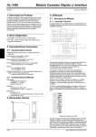
2.4 Cable stress
(1)The wayof clamping the cable must be fully examinedso that flexing stress and cable's own weight stress are not
applied to the cable connection.
(2) In any application where the = N O motor moves, the cables shouldbe free from excessive stress. When the= N O
motor moves, e.g. the encoder cableand servo motor wiring are contained in a cable bearer, run the cables so that
their flexing portionsfall within theoptional encoder cablerange.
Fix the encoder cableand power cable of the servo motor.
(3) Avoid any probability that the cable sheath rmght be cut by sharp chips, rubbed by a machine corner or stamped
by workers or vehicles.
(4) The flexing lives
of the cables are shown below. In actuality, provide a littleallowance for these values.For install
ation on a machine where the servo motor will move, the flexing radius should be made as large as possible.
a : l m g flexing-iife encoder cable
MRJCCBLOMH
MRJHSCBLOM-H
MR-ENCBLOM-H
b : StanCBrd encoder cable
MRJCCBLOM-L
MRJHSCBLOM-L
7
10
20
40
70 100
200
Flexingradius [m]
Note: This graph gives calculatedvalues whichare not guaranteed.
3. SIGNALS AND WIRING
3 SIGNALS ANDWIRING
~~
A
Any person whois involved in wiring should
be fully competent to do thework.
Before starting wiring, make sure that
the voltage is safe in the tester more than10
minutes after power-off.
O t h e r w i s e , you may get ane l m shock
Ground the servo amplifier and servo
the motor securety.
Do notattempttowirethe
servo a m p l i r and s e ~ motor
o untiltheyhavebeen
installed. Otherwise, you may get an electric
shock
The cables should not
be damaged, stressed excessively, loaded heavily, or pinched.
Othewise, you may get an electrics h e
Wre the equipmentcorredy and securely. O t h e r w i s e , the sew0 motor may
misoperate, resutting ininjury
Connect cables to
correctterminals to prevent a burst,faun, etc.
Ensure that polarrty (+,
-) is correct Otherwise, a burst, damage, etc. may occur.
The surge absorbing diode installed
to the DC relay designed for control
output
should be fdted in thespecmed direction. O t h e f w i s e , the signalis not output due to
a fault, disabling the emergency stop and other protective
circuits.
(DC24V)
A CAUTION
Control output
Use a noise filter, etc. to minimize the influence
of electromagnetic interference, which
may be given to electronic equipmentused near the servo amplifier.
Do not install a power
capacitor, surge suppressor or radio noise fitter
(FR-BIF option)
with the power lineof the servo motor.
When using the regenerawe brake resistor,
switch power offwith the alarm signal.
Othewise, a transistor fault or the may
like overheat the regenerative brake resistor,
causing a fire.
Do not modrfy the equipment
POINT
CNLA, CNlB, CN2 and CN3 have thesame shape. Wrong connection
connectors will lead to a failure. Connect them correctly.
3- 1
3. SIGNALS AND WIRING
3.1 Connection Diagram
3.1.1 Standard connection example
1
When connecting the e
brake option, always
disconned
the
jumper
from a w s s P-D.
External pulse
input
r
(Note 4)
CNlA
(Note 4
CN2
1
I
~
(Note 4)
CN3
Proxirnty DOG switch
&NO on
Zero point return
completion
[
(Note 4)
CNlB
Fomard rotation strokeend
Note 6, Reverse rotation stroke end
Program inputI
Program input2
(Note 4)
CN3
output 1
output 2
Foward start
Program No. selection 1
Program No. selection 2
Reset
Do not dnned when using
an externalpower supply.
(Note 7)
(Note 8 )
Servo motor
Program output 1
Movement complete
Alame
Ready
Override
Analog toque limit
3- 2
3. SIGNALS AND WRING
Note: 1. To prevent an electric shock,always connect the protective earth @‘E)terminal of the servo amplifier to the
protedive earth
of the control box.
l
ibe fad@ and
2. Connect the diode in the correct drection If it is connected reversely, the servo amplifier w
(Pa
will not output signals, disabhg the emergency stop and other protective circuits.
3. The emergency stopswitchmust be installed.
4. CNIA, CNlB, CN2 and CN3 have the sameshape.Wrong connection of the conn&m will lead to a fault.
5. The s u m of currentsthat flow in the externalrelays should be 8OmA max. If it exceeds N h A , supply interface
power h m external.
6. When startmg operation, always connect the forward/reverse rotation stroke end signal ( I S N U P ) with SG.
c
l
s
e
d contacts)
(Normallyo
7. Trouble (AU’vlJ is c
o
d
with COM in normal a
a
lr
m
&condition
8. The connection method changes with theservo motor seriw.Refer to W o n 3.3.
9. The pins withthe Same signal name are connectedin the servo amplifier.
10. A sngle-phase 230V power supply may
be used with theservo amplifier of MRJ2-70C-S100or less.
However, it cannot be used when the
servo a m p f i r is combined with the HCSF52/53 sem motor.
Connect the power supply to L1 and & terminals and leave & open
11. When using override 0
, make theoverride selection (OVR)device available.
12. When using torque limit (ITA), make theexternal torqueh i t selection (TL) devices avadable.
3- 3
3. SIGNALS AND WlRlNG
3.1.2Common line
The following diagram shows t h e power supply and its common line.
Manual pulse genera
MR-HDW1
G-
I3
-7
I L G
I ~
--
d
I
i
-
3. SIGNALS AND WIRING
3.2 Servo Amplifier
Onty the specified voltage should be applied to each terminal. Otherwise, a burst,
damage, etc. may occur.
A
3.2.1 Terminal blocks (Power supply system)
(1) Signal arrangement
Terminal block signals are as listed below:
MRJ2-100CSl00
MRJ2-@XS100
n
F-l
Terminalpositions
il
T
' 3)
Re
R
N
(Phoenixcontadmake)
(PhoerrbcContadmake)
L
Ll I 2 Ls
E
2)
L l k l 3 U V W
3- 5
3. SIGNALS AND WIRING
-
(2)Signals
,
Signal
Symbol
Main circuit power input terminals
Supply L,, and 5 with the following power.
MRJ2-1OC to
MRJ2-70CS100
MRJ2-1O
o
c
l00 to
MRJ2350CS100
Main drcuit power supply
(Note) Single-phase 23OVAC,
m60Hz
Ll*b
X
_____~~
~~
~~
Note: Cannot be used b r combination withthe servo motor HCSF52.53.
Servo motor power output terminals
Connect to the servo motor power supply terminals (v,V, W).
~
Servo motor output
Control circuitpower supply
~~
P,C, D
Regenerative brakeoption
Control circuitpower input terminals
Supply L,, and b,with single-phase200-230VAC, 50/60Hzpower.
L,, and k1should be in phase withL,and b,respdvely.
Regenerative brakeoption connection terminals
C and D are factoryconnected
When using the regenerative brake option,always remove wiring h m across
P-Dand connect the regenerative brake option across
P-C.
Do not connect.
Ground terminal
Connect this terminal to the protective earth (PE) terminals of the servo motor
and control box for grounding.
&
I
-
Protective earth (PE)
I
3. SIGNALS ANDWRING
3.2.2 Connectors (I/O Signals)
(1) Signal arrangement
CNlA
CNlB
LG
OUT1
Pi5
PS1
CN2
Amplifier's internal wiring
T h e connector frames
are connected with the
PE(earth) terminal inside
the servo amplifier.
3- 7
:---+j-#
19
3. SIGNALS AND WIRING
(2) Signal explanations
1) CNlA
Descnptron
VO Division
Used to input 24VDC*10% for input interface.
Driver power input terminal for digital interface.
COM of each connector is connected in the s
e
w amplSer.
When usingan external power supply, connect power
a
supply of 24VDC
2oomA or moreto this terminal.
When using a pulse
train in the open collector, supply 24VDC to this
2
12
DOG
8
Common tenninalbr VDD and COM and isolated &om LG.
Used to output 15VDC. Power supplyterminal br VC and TLA
Common terminal b r VC, TL4, M o l , M02 and P15R
USXI to enter a 2-phase pulse t r a i n .
1)In the open collector system (max. input m u e n c y 200kpp-s)
A phase pulsetrain a m PP-SG, B phase pulsetrain auuss N'P-SG.
2)In the mrential receiver system( m a x input h q u e n c y 4OOkpp-s
A phase pulse train across PG-PP, B phase p u k train aNG-NP
Proximity dog signal input terminalfor manual zeroing.
When terminals DOG-SG are opened, the proximity dog signal is
DI-1
detected.The polarity of dog detection input can be changed with the
parameter.
Parameter No.8
0000 (initial value)
0100
ZP
18
Polanty of Proxkni Dog Detection Input
DOG-SG are openedDOG-SG are Shorted
ZP-SG are c o ~ e c t e don completion of zeroing.
In the absoluteposition system, ZP-SGare connected when theservo
amp&r is ready to operate butare disconnected if
1) SONSG are opened;
2) EMG-SG are opened;
3) RES-SG are shorted;
DO-1
4) Alarm occurs;
5) Limit switchopens;
6 ) Zeroing has not been made afterthe purchaseof the product;
7) Zeroing has not been made afterthe occurrence of absolute
position erasure (A 2 5 ) or absolute position counter warning (A E3);
8)Zeroing has not been made a h the changing of the electronic gear
value;
9) Zeroing has not been made afterthe absolute position system was
made valid; ords
10) The ST1 coordinate system(OOOO in parameter No.1) has been
SON
19
-SD
Plate
changed.
Operation-ready signalinput terminal.
When SON-SG are shorted, the base drcuit is switched onand the servo
ampli6er is ready to operate.
When theyare opened, the base circuit is shut off and the servo motor
coasts.
Connect one end of the shielded cable.
DI-1
3. SIGNALS ANDWRING
2) CNlB
sinal Name
--
Desaiptton
Symbol Pin No.
Used to output +24V*10% to across VDD-COM.
3
VO Division
VF Internal power supply VDD
Digital YF power supplyi
COM
13
P15R
11
3 n t r o l common
LG
Forward rotation stroke e ISP
5d
16
LSN
17
nput
DC15V power supply
Digital I/FCommon
Reverse rotation s m k e e
10, 20
SG
1
ad
When using this power supply for digital interface, connect it with COM.
Permissible current: 8OmA
Used to input 24VDC*lO% for input interface.
Driver powerinput terminalfor digital interface.
COM of each connectoris conneded in the servo amplifier.
When using an external power supply, WM& a power supply of 24VDC,
2OOmA or moreto thisterminal.
Used to output +15VDCto aQoss P15R-E. Used for VWl'LA power
supply.
t24VDC common terminal fix VDD, OM,
etc. and isolated fromL G .
Common terminal for VC,"LA, M o l , M 0 2and P15R
Forwar&reverse rotation stroke endsignal input terminals.
To start operation, short ISP-SG or LSN-SG. When theyare opened,
h e servo motor is stopped suddenly andservo-locked.
Aacss LS AaossLS
PSG
NSG
PI 1
8
%
g
r
a
minput 2
PI2
9
3tart
ST1
7
PSO
5
14
Forward rotationstart
?rowNo. selection
PS1
I
1
1
0
0
0
1
0
X
0
0
X
1
%gram input 1
Operation
CCWdirecbon
CWdirecbon
X
X
0
0
Note. OOpen,l:Short
%gram input device terminal 1
luring to running program, signalto commanded SYNC(1).
?roogram input device terminal 2
luring to running program, signalto commanded SYNC(2)
start signal input terminal
In automatic operationmode, operahn starts as wan as ST1-SG are
shorted.
[n zeroing mode, zeroingstarts as scan as ST1-SG are shorted.
[njog operation mode, the sem motor rotates in the forward rotation
W o n while STI-SG am shorted
Vote: Forward rotation denotesthe direction inwhich the addressis
incremented.
?rogram number selection input terminal
?SO and PS1 relationship betweensignal status and operation are as
bllows.
I PS2 I PS1 I PSO I Selected program No I
It ia necessarg to auocate
by parameter No.59 to 63.
1
1
-
1
0
1
1
Program N0.7
Program No.8
0:Open 1:Short
3- 9
DI- 1
DI-1
DI- 1
DI- 1
DI-1
DI-1
3. SIGNALS ANDWIRING
-
i
S’ M I Name
Pin No.
Programoutput 1
Movement completion
4
PED
x
Trouble
Alarm reset
RES
6
18
19
15
UO Division
Desaipfion
Program output 1device
OUT1 is device signal when commanded OUTON(l)/OUT
OF(1) in the
Program.
It is possible turn on time by Parameter No.54
Movement completionsynchronous output device.
After the command remainingdistance and smoothing reach zer0,this
signal is output (PED-SGare ~ ~ e c t ewithin
d ) the drwppulses set in
Parameter No. 12
DO-1
Trouble signal output terminaL
ALM-SG are disconnected when the protxtivecircuit is activated to
shut off the base circuit at power OE
They are connected in normal condition
at power off
Ready output termjnaL
RSSG are connected when the servo amplifier is ready to operate
without kilure after servwn.
Alarm reset signal input device.
Short RESSG to deactivate the alarm.
When I 3 0 1 0 is set in parameter No.22, the base circuit is shut off while
RESSGare shorted
The bllowing alarms cannot be deactivated:
DO-1
Indication
Name
Indication
Name
I
I
A 12
Memory error 1
A 15
Memory error 2
I 1:;
I
I
I
A 16
IEncodererror
/Boarderror2
Board
3
error
hmde
vc
3xternal torque Lmit
TL4
Shield
SD
1
I
I
I
I
Motor output
groundfault
Regenerative
1 1 :1
I I
A 37
Plate
1
I Parametererror I
~Overloadl
Overload 2
2
.lo to +1OV is applied to aVCLG to limit the servo motor speed
Qply
-1OM
for
O[%]
override,
O
M for loo[%], orlOM b r 200[%].
12
1
3 to +1OV is applied to across TLA-LG to limit the servo motor-generated
brque.
Qply O
M for 0 torque or l 0 M for max torque.
bmect one end of the shielded cable.
DO-1
DO-1
DI-1
3. SIGNALS AND WIRING
3) CN3
5 and Rs232C fun&ons cannot be used together.
hort "15"and "10" at tbe last axis.
3 - 11
3. SIGNALS AND WIRING
3.2.3 Additional fundon devices
By using the Windowsm based Software or parameter, you can assign the signals given in this d o n to the pins of
nectors CNlA and CNlB, in addition to the signals in Section 3.2.2.
'ins which accept different signals
Input-only pins
Output-only pins
Note: Terminal CNU-19 can be set as either INPUT or OUTPUT by Parameter N0.58.
(2)Assignable devices
1)Input devices
Device Name
No assigned function
Emergency stop
-
EMG
Ovemde selection
OVR
External torquelimit
selection
TLO
Internal torquelimit
TL41
selection
Proportion control
program input
3
II
Reverse rotationstart
AutomaticlManual
selection
Desaipbon
Symbol
PI3
ST2
1
No function is a
s
s
i
g
n
d
Emergency stopinput device.
When EMGSG are opened, the servo amplifier is placed in theemergency stop
status, the servo switches o g and the dynamic brakeis operated to bring the servo
motor to a sudden stop.
Short EMG-SG in the emergency stop status to cancel the emergency stop status.
Override selection inputdevice.
ShortOVRSG to makeovemdevalid
External torque limit selection input
device.
Short TLO-SG to make external analog torque limit valid
For more hhnnation, refer to Section 3.2.5.
Internal torquelimit selection input device.
open TL1-SG to make the torquelimit value set in parameterNo.28 (JY-0) valid, or
short themto make the value set
in parameter No.29 ("Ll)valid
For more information, refer
to Section 3.2.5.
Pmportion control input device.
Short PCSG to switch the speed amplSer from proportional integral type to
proportional type.
Program input device terminal.
During to running program.PI3 is device signal when commandedSYNC(3)
Reverse JOG start signal input device.
In jog operation mode,the servo motor rotates in the reverse rotation direction
while ST2-SG are shorted
Note: Reverse rotation denotes the direction
in which the addressis decremented.
Automatidmanual mode selection signal input terminal.
Short MDO-SG to choose the automatic operation mode,or open them to choose
the manual operation mode.
3 - 12
VO Division
DI-1
DI-1
DI-1
DI-1
DI-1
DI-1
~~
DI-1
DI-1
DI-1
3. SIGNALS AND WIRING
Device Name
'rogram No. selection 2
Symbol I
Description
PS2 Program number selectionsignal input device.
VO Division
Dl-1
During theprogram operation mode, it is selected whenST1 signal upedge.
remporary stoplmtart
STP
Note: O:Open, 1:Shot
Temporary stoptrestart input device.
Short STP-SGduring automatic operationto make a temporarystop.
Short STP-SGagain to make a restart.
Shorting the f o r w d r e v e r s e rotation start m g d during a temporary stop is
ignored.
nput pulse m a d c a t i o n
election
TPO
Switching h m automatic mode to manual mode during a temporary stop clears
the remainingmoving distance.
During zeroing and jog operation, the temporary stoplrestartinput is ignored.
Refer to Section 4.2.2, (4).
Input pulse magm6cation selection input device.
TP1
Input putse magnification
10 times
100 times
1
Note: 0:TPUTF'O-SG open
1: TPlrrPO-SG shorted
3 - 13
DI-1
3. SIGNALS AND WIRING
2) Output devices
Devii Name
No assigned function
Electromagnetic brake in
terlock
MBR
Position range output
POT
warning
WNG
Battery warning
BWNG
Limiting torque
TLC
Temporary stop
PUS
Rogram output
OUT2
OUT3
SYNC synchronous
SOUT
DUtoUt
-
Dymmc brake interlock
VO Division
Desaptbn
No function is assigned,
Electromagnetic brake interlock
output device.
Used to output theinterlock signal for electromagnetic brake.
MBR-SG are disconnectedat servo-offor alarm occurrence.
range output device.
POT-SG are COM& when the numberof actualposition address is in the preset
position range.
Warning output device.
WNG-SGare C O Mwhen
~ warningOOCUZS.
Open innormal condition.
Battery warning output device.
BWNG-SG
connected when the open battery cable warning (A 9 2 ) or battery
warning (A 9F)occUrs.
Open inn o d condition.
Torque limitingdevice.
when
t . the
d internally or externally
set torque limit value is
TLCSG are ~ 0 ~ e ~
reachedTemporary stop device.
PUSSG are connected when decelerationto a stop is started by the
temporary stop signal PUSSG is disconnected when operationis resumed
by making the temporarystop slgnal valid again.
Program output device.
OUT2 is device signal when mmmandedOUTON(2YOUT OF(2)in the program.
OUT3 is device slgnal when commandedOUTON(3)OUT OF(3)in theprogram.
SYNC synchronous output device.
SOUT-SG are c
o
d
when waitingfor SYNC( ) command
Dynamic brake interlockoutput device.
DBR
DO-1
DO-1 Position
DO-1
DO-1
DO-1
DO-1
DO- 1
DO-1
DO-I
(3) Notes of output signal
If the m a h e is directly driven by the output device of MRJ2-Sl00, you need the following attention.
MRJ2-SlOO can have 6 output device (CNIA-18, CNlB-14,-6, -18,-19,and reversibledevice CNIA-19).
As for CN1B-6, during amplifier initialkingp e r i o d , it differ from condition ofother output device.
Lll,L21
CNl B-6
X
CN1El8
X Outpd d pauneter semng fundion
.
CNlB-19
X-
CPU initializing
4
Servo arnplrfer mializing me-lsec
3 - 14
OT
less
-c
~f parameter s e t t q ~
r
of parameter senmg tunam
n
3. SIGNALS AND WIRING
3.2.4 Override
POINT
When using theoverride, make theoverride selection(OW)device available.
--
The override (VC)may be used to change the servo motor speed. Thefollowing table lists the signals and parameter
related to the override:
I
Name
Item
Analog input signal
Contact input signal
Parameter
1
1
Remarks
Ovemde 0
Override selection ( O W
No.25 override o f k t
Set-up SORware seaing required.
I
1-999to999mv
(1) Overn.de (VC)
By applying a voltage(-10 to +low to the override (VC)termud, change valuescan be set h m outside
the ratio of actual speed
consecutively. Thefollowing graph shows the relationship between the input voltage and
to preset speed.
Refer to the following diagram when using the15V power output (PER) of the = N O ampmer:
Servo amplifier
Override
seledion
Override (VC)appliation vokage
(2) Ovenide selection(OVR)
Used to make the override (VC)valid or invalid.
(OW)
r
w
I
LJ
Servo amplifier
Override seledion
(OW
Override (VC)
-10 to +lOV
1
1
~~
Motor
Using the override selection(OVR),choose a change value as follows:
A
I
m OW-SG
hen
Short
Speed Change Value
No change
I Override (VC)
setting is made valid
I
(3) Ovenide offset (parameter No.25)
Using parameter No.25, the offset voltagecan be set relative to the inputvoltage for the override (VC).
The setting is between -999 to 999mV.
3 - 15
3. SIGNALS AND WRING
3.2.5 Torque limit
POINT
To use the torquelimit, make the external torquehmit selection (ITLO) device and
internal torque limit selection
ml)device available.
The following table hts the signals and parameters related
to the torque limit:
kern
Analog input signal
Contact input signals
Name
Remarks
External torque limit W)
External torque limit seledion
Internal torque limit selection
m)
ml)
Servo Configuration Software setting
required.
Contact output signal
Limiting torque 0
0 to 1
w
m
Parameters
No.% internal torque limit 1
No.29 internal torque limit 2
No.% torque limit o & e t
No.20 selection function 2
Selection of t h e rotation direction in which
torque limit is executed
OtolOo%
-999to999mV
The torquelimit is available in two types: internal torque limit setin parameters and external
torque h u t using
analog inputsignal.
This function limits generated torque on the assumptionthat the maximumtorque of the servo motor is 100%.
(1) Internal toque limits 1, 2
Use parameter No.28 and 29 to set the internal torque limit values. Thefollowing graph shows the generated
torque relativeto the setting.
100
Toque limit value [%I
(2) Externaltoque limit VIA)
By applying avoltage (0to 1OV) to the external torquelimit (TLA) t e r m i n a l , limit values can be set from outside
consecutively. The following graph shows the relationshpbetween input voltage and limit value.
Depending on theservo ampMer, thelimit value has about 5% variations to the inputvoltage. As thismay not
cause torque to be h t e d sufsciently at less than O.O5V,use ths function at thevoltage of 0.05V or more.Refer
to the following diagram when using the
15V power output (€'15R) of the servo amplifier:
Servo a m p l i r
1
TLA Application
Connection
Voltage
vs.
Example
Torque Limit Value
3 - 16
3. SIGNALS AND WIRING
(3) External toque limit selectJon (TLO), internal torque limit selection (TI-1)
To use the external torqueh u t selection (TL,€))and internal torque limit
selection (TLl),make them available
using the CodgurationSoftware (refer to Chapter 6).
These inputsignals may be used to choose the torque limit values made
valid.
(a) External torque limit selection ('Il.4)
Used to make the external torque
limit (TLA) valid or invalid.
Servo amplifier
I
I
Externaltoraue
limit seledion
CnO)
Externaltoque limit
0-w
0-1
ov
Using the external torque
lunit selection (TL,€)),choose the h u t value as follows:
A
Torque Limit Value
m TLGSG
open
Short
No h t
E a m a l torque limit (TLA) setting is made
valid.
(b) Internal torqueh t selection (TL1)
Used to change the internal torque
hit.
Servo amplifier
-2zP p
Internal torque limit selection
C
n
)
l
I
Internal torque
limit 1
Internal toque
Using the internal torque limit
selection ("Ll), choose the limit value as
follows. When TL1-SG are shorted,
the smaller valueof the internal torqueh
t
s 1and 2 is chosen:
AcrossTLlSG
open
Short
Torque Limit Value (Parameter)
Internal torque limit 1
Internal torque h u t 1 ifinternal torque h t 1 < internal torque limit 2
Internaltorque limit 2 if internal torque limit 1 > internal torque limit 2
3 - 17
3. SIGNALS ANDWIRING
(4) External toque limit offset (parameterNo.26)
using parameterNo.26, the offset voltage can be set relative to the input voltage of the external torque limit
fIzA). The setting is between -999 to 999mV.
(5) Selection of rotation direction for torquelimit execution (parameterNo.20)
Using parameter N0.20, the rotation dmction for torque h t execution can be selected.
.
Parameter No20 Setting
Rotation DirectionfotToqueLimit Exearbjon
CCW direction
CWdirection
0001
0
X
non2
X
0
For example, when0001 is set in parameter N0.20,torque h t is executed in the CCW direction but not in CW
cb€!CtlOIl.
\
CW rotation: Torque limit is not executed.
3. SIGNALS ANDWIRING
3.2.6 Alarm Occurrence Timing Chart
A
When an alarm has occurred, remove
its cause, makesure that the operation signalis
CAUTloN not being input, ensure safety, and reset the alarm before restaarting operation.
When an alarm OCCUTS in the servo amplSer, thebase circuitis shut off and theservo motoris coated to a stop. Switch
off the main circuitpower supply in the external sequence. To reset the a l a r m , switch the control circuit power supply
off, then on.
However, the alarm cannot be reset unless its cause of occurrence is removed.
power supply
ON
OFF
Power off
!
t rower on
I
0
I
Base circuit
Dynamic brake
R e m v e cause of trouble
Precautions for alarm Occurrence
1)Overcurrent, overload1 or overload 2
If operation is repeated by swikhing control circuit power off, then on to reset the overcurrent (A 32), overload 1
(A 50) or overload 2 (A 51) alarm after its occurrence, without removing its c a u s e , the servo ampfier andservo
motor may become faulty dueto temperature rise. Securely removethe cause of the alarm and also allow about
30 minutes for cooling before resuming operation.
2) Regenerative alarm
If operation is repeated by switching control circuit
power off, then on to reset the regenerative (A. 30) alarm
after its occurrence, t h e e x t e n dregenerative brake resistorwdl generate heat, resultingin a n accident.
3) Instantaneouspower failure
If a powerfailure continues 15msor longer, the undervoltage (A 10) alarm d occur. If the power f d u r e s t i l l
persists for 20ms or longer, the control circuit is switched off. When thepower failure is reset in tlus state, the
alarm is reset and the
servo motorwill start suddenly if the servo-on signal (SON is on. TOprevent hazard,
make upa sequence whichwill switch off the servo-on signal (SON) if an alarm OCCUTS.
4) Incremental system
When an alarm occurs, the home positionis lost. Whenresuming operation after deactivating the a l a r m , make
a returnto home position.
3 - 19
3.
SIGNALS AND WIRING
3.2.7 Interfaces
This section gives the detailsof the UO signal interfaces (refer to UO &vision in the table) inhcated Sections
in
3.2.2
and 3.2.3.
Refer to this section and connect the interfaceswith the external equipment.
(1) Digital input interface Dl-1
Give a signal with a relayor open collector transistor.
Source input is also possible. Refer to (5)
. . in this sedion.
For use of internal power supply
Servo amplifier
,
I
(Note)
For a transistor
IVDD
73"""
ICOM
.
I
24VDC
R:Approx. 4.7kG
R: Approx. 4.7kR
I
i
ISON. e62
-
SON, e62
SG
I
V CES1.OV
I CEOIlOOpA
+
I
Note: ThLs also applies to the use ofthe e
x
e
td power supply.
(2)Digital output interface DO-1
A lamp, relayor photocoupler can be driven. Provide a&ode (D) for an inductive load,or an inrush current
suppressing resister(R) for a lampload. (Permissible current:4OmA or less, inrush current: l O o m A or less)
1)Inductive load
For use of internal power supply
Servo amplifier
For use of external power supply
Servo amplifier
connected as shown,
the servo amplifier
connected as shown,
the servo amplifer
COMtr
Load y r 2 7 V D C or
w ,etc.
SG"
3. SIGNALS AND WIRING
2) Lamp load
For use of extemal power supply
For use of internal power suppty
Servo amplifer
Servo amplifier
(3)Analog input
Input inpedance
10-12kn
Servo amplifier
I ,
, I
i i
LG
----_--_--_
b
D
(4) Analog output
output
+1ov
Max. 1mA
Servo amplifier
1Okn
Rea Ing In
1
I
;;
LG , ,
one or both
direcbons
-
1 m A meter
3 - 21
3. SIGNALS ANDWRING
(5)Source input interface
When using the inputinterface of s
o
Source output cannotbe provided.
type, all DI-1input signals are of source type.
Foruseofextdpowersuppiy
Servo amplifier
*
R: Approx. 4.7kn
(Note)
For a transistor
r
Approx. 5mA
.
V CESS1.OV
I CEOslOOM
Note: Thisalso applies to the use of the externalpower supply.
200mAamae
I
-1
R: Approx. 4.7kn
r
3. SIGNALS AND WIRING
3.3 ConnectJon of Servo Amplifier and Servo Motor
3.3.1 Connectioninstructions
AWARNlNG
A CAUTloN
Insulate the connectionsof the power supply terminals to prevent an electricshock.
Connect thewires to thecorrect phase terminals(U,V, W) of the servo amplifier and
servo motor. Otherwise, theservo motor will operate improperly.
Do not connect AC power suppty directly to the servo motor. Otherwise, a fault may
occur.
(2) For groundmg, connectthe earthcable of the servomotor to the protective earth (€'E)e
t
d of the servo
amplijier andconnect the ground cableof the servo ampMer to the earthvia the protective earth of the control
box.
COfdldbOX
Sew
aw-r
SeNo mdor
900
PEtermiral
I@
(3) Supply exclusive2 4 W C power to the brakelead of the servo motor with electromagneticbrake.
The connection methodM e r s a m r d m gto the seriesand capacity of the servo motor and whether or not the servo
motor has the electromagnetic brake. Perform wiring in accordance with ths section.
3 - 23
3. SIGNALS AND WIRING
3.3.2 Connection diagram
The following table lists d
g methods accordmg to the servo motor types. Use the connection diagram which
codorms to the servo motor used. For cables requiredfor wiring, refer to e o n 14.2.1.For enccder cableconnection,
refer to Section 14.1.2.
For the cable side connector, refer
to Chapter 3 of the servo motor technical mformation.
--
ConnectDn Diagram
Servo Motor
SammaoT
HCMF053 (B) to 73 (B) (-uE)
HA-FFo53 (B) to 63 (B)
HCUF13 (B) to 73 (B)
Note: 1. To prevent an electric shock, always connect the protective earth (PE)termiual
servo amplifier to the protective earth (F'E)of the control box
Note: 2. This circuit appliesto the servo motor with electromagnetic brake.
3. For the HA-FF series, mnnect the ground cable to the earth terminalof the servo motor.
S
HA-FFO53 (B) to 63 (B)-uE
HGSF201 (B) * 301 (B)
HCSF202 (B) * 352 (€3)
HCSF353 (B)
HGUF202B
Note: 1. To prevent an electric shock, always connect the protectiveearth (PE)terminal
servo amplifier to the protective earth (PE)of the control box.
Note: 2. This circuit appliesto the servo motor with electromagnetic brake.
Sew amplifier
Servo mdor
HCSF52 to 352
HCSF52B to 152B
HGRFlO3 (B) to 203 (B)
HC-UF72 to 202
HGUF72B. 152B
Vote: 1. To prevent an electric shock, always connect the protectiveearth (PE)terminal
servo amplifier to the protectiveearth (PE)of the control box
Vote: 2. This circuit applies to the servo motor with electromagnetic brake.
3. SIGNALS AND WIRING
3.3.3 I/O terminals
(1) HC-MF(-UE) series
Encoder connectorsg~lanangement
tad rwnd uinping terminal 1.25-4
mite :vphase
Back :wphase
24-310.3m
W& en&insubted rwnd crinping
termirtal1.25-4
(AMP maka)
(2) HA-FF series
Eartfi terminaL M3 saew
(3)HC-UF 3000r/minseries
Encoder connectM
s g ~arrangement
l
u
Encoder cable 0.3m /
W t h connector
,
172169-9 (AMP make)
\
\
Power s u ~ ~ lead
l v 4-AWG19 0 3m
.
I
,
~
(wth end-Insulated round almplng
termlnal 1 25-4)
VCTF 2-0.52 0 5m
Red
U phase
( w ~ t hend-Insulated
round
mite : phase
crlmplng terminal 1.25-4)
5lack w phase
[Brake cable
4
'
Greenfyellow : Earth
3 - 25
3. SIGNALS ANDWIRING
(4) HA-FF-UE series
I
I I1
/
Encoder conned0
I
I
I
Servo Motor
HA-FF053(B)-UE
to
HA-FF63(B)-L%
Power supply connector sig
nal arrangement
CE05-2.414s-2PD-B
Connector
For encoder
For brake
MS3102A.20-29
MS3102ElOSL4P
Encoder connectorsignal
arrangement
Brake connectorsignal arrangeme
nt
MS3102El.OSL4P
@
G
H
L
G
-
LG
P5
-
N o t e ) B2
Note: 24iBC
wlthout polarih.
3. SIGNALS AND WIRING
(5) HC-SF HC-RF
*
HC-UF2000 r/min series
Servo Motor Side Connectors
I
Mm
Servo Motor
I/
For power suppty
For encoder
lrm *rfo i
r power is shared
Imcon ectorLb I
r power is shared
CEO5-2422-
The connector fo
r power is shared
CEO5-2A24-
hIs3102410SL
Power supply connector signal arrangement
CE05-2A24-IOPD-B
CE05-2A22-23PD-B
w
I
1 - 1
(Earth)
T
-
Encoder connector signal arrangement
MS3102A20-29P
MS3102ElOSL4P
k Y
Pln
MRR
BAT
LG
3 - 27
w v l
3. SIGNALS AND WIRING
3.4 Input Power Supply Circuit
IA
When the servo amplifier has become faulty, switch power
off on the servo amplifier
power side. Continuous flow
of a large currentmay cause a fire.
Use the trouble signal to switch power off. Otherwise, a regeneratwe brake transistor
fault or the likemay overheat the regeneratwe brake resistor, causing a fire.
CAUTloN
I
II
(1) Connection example
Wire thepower supply and main circuitsas shown below. A n c - h breaker (XTl3) must be used with the input
cables of the power supply.
st&
OFF
ON
(Note) Three-phase
200 to 230AC
or
Single-phase
230VAC
Note: U s not provided for single-pbse 230V p c m e r supply.
(2) Power-on sequence
1j Always wire the power supply as shown in above (1)in thLs section using themagnetic contactor with the main
circuit power supply (three-phase 2OOV L1,L,
b,single-phase 230V: L1,L+J. Corhgure up az1 external
sequence to switch off the magneticcontactor as soon as an alarm occurs.
2 ) Suitch on thecontrol circuit power supply L11,Ll simultaneously with the maincircuit power supply or before
switchmg onthe main circuit power supply.
If the main circuit power supplyis not on, the &play shows the
correspondmg warning. However, by switchmg on the main circuitpower supply, the warningh a p p e a r s a n d
the servo a m p u e r d operate properly.
3j Theservo ampfier can accept the servo-on signal (SON) about 1 second after the maincircuit power supply is
switched on. Therefore, when SON is switched on simultaneously with the three-phasepower supply, the base
circuit udl switch on in about 1 second, and theready signal (RD) will switch on in further about2Oms. m h l g
the servo ampl&er ready to operate. (Refer to paragraph (3) in ths section.)
4)\??len the reset signal (RES) is switched on: the base circuit is shut off and theservo motor shaft coasts.
3 - 28
b
3. SIGNALS AND WIRING
(3)Timing chart
Base circuit
(4) Emergency stop
Emergency stop (EMG) can be used by malang device setting on the Set-upSoftware.Make upa circuit whch
shuts off main circuit poweras soon as EMG-SG are opened at an emergency stop.
To ensure safety, alwaysinstall a n external emergency stop switch across EMG-SG. By h n n e c t i n g EMG-SG,
the dynamic brake is operated to bring theservo motor to a sudden stop. At
t h s time, the*lay
shows the servo
emergency stop warning (A. E6).
During ordmary operation, do not use the externalemergency stop signal to alternate stop and run.
Also, ifthe start signal is on or a pulse train is input during an emergency stop, the servo motor wdl rotate as soon
as the warningis reset. During a n emergency stop, always shut off the run command.
Servo amplifier
3 - 29
3. SIGNALS AND WIRING
3.5 Servo Motor with Electromagnetic Brake
Make up the electromagnetic brake operation circuit
so that itis actrvated not only by the
by an external emergencystop signal.
servo amplifier signals but also
Shut c4f bj serveon s i g n 1 OFF,
alarm or eleclromgnetic brake signal.
A
Shut ot7 emergency stop
signal (EMG).
Servo motor
CAUTION
24VDC
Sote the following when the servo motor equipped with electromagnetic brake is used for applications requiring a
brake to hold the motor shaft (vertical hft applications):
1) In the device setting of the Set-up Software, make the electromagnetx brake
interlock signal (MBR) available.
2) Do not share the24VDC interface power supply between the interface and electromagnetic brake.
Always use the power supply designedexclusively for the electromagnetic brake.
3 ) The brake ulll operate when the power (24TiDC) switches off.
4)WMe thereset signal is on, the base circuit is shut off. "hen using the servo motor with a vertical shaft,use the
electromagnetic brake interlock signal (MBR).
(1J Connection diagram
Servo motor
Servo amplifier
L
VDD
Emergency
7
COM
MBR .
(2) Setting
1)In the device setting of the Set-up Software,make theelectromagnetic brake interlock signal (IvlBR) avdable.
2 ) Using parameter N o 3 3 (electromagnetic brake sequence output), set a t m e delay h m electromagnetic brake
operation to base circuit shut-off as in the timingchart shown in (3) in t h s sechon.
3.SIGNALS AND WIRING
(3) Timing charts
1) Servo on signal command (from controller) ONiOFF
The following chart shows theway of holdmg the motor shaft in vertical hft applications. Adjust Tb to minimize
a drop after servo-off. The servo motorstarts coasting 'I%
after the servo switches off. When using thls sequence.
therefore, the servo should be swltched off after the servo motor has stopped.
2) Emergency stop signal (EhlG) OWOFF
Servo &
o
rspeed
3 - 31
3. SlGNALS AND WIRING
Servo molor s p e d
4) Main circuit power off
Servo mdor speed
Base circuit
ON
OFF
I
Y
A i
3. SIGNALS AND WIRING
3.6 Grounding
Ground the servo amplifier and
servo motor securely.
To prevent an e l m c shock, always connect the protective earth (PE) terminal of the
servo amplifierwrth the protecbve earth(PE) of the controlbox.
AWARNlNG
The servoa m p G e r switches the power transistor on-off to supply power to the servo motor.
Dependmg on the wiring and ground cablerouting, the servo a m p u e r may be affected by the switching noise (due to
dddt anddv/dt) of the transistor.To prevent such a fault, refer to the following hagram and usea flat mesh copper
cable, w h c h is as large as possible (3.5mm2or larger is desirable), for groundmg.
To conform to the EMC Directive. refer to the EMC I N S T U A T I O K GUIDELJNES (IB(NA)67310).
Conbol box
MC
(Note)
3-phase
200 to 230VAC
v
i
CN2
- 1
or
SignaCphase
230VAC
L
b#
CNIA CNIB (
J
I'
Must be grocrnQd by cable.
Note: U is not provied for single-phase 230V
powers w .
3 - 33
3. SIGNALS AND WIRING
3.7 Servo Amplifier Terminal Block (TE2) Wring Method
1)Termination of the cables
Solid wire: f i r the sheath hasbeen stripped, the cablecan be used as it is. (Cable size: 0.2 to 2.5mmq
l’hsted wire: Use the cable after stnpping the sheath and
h i s t i n g the core. At t b time, takeCare to avoid a
short caused by the loose wires of the core and the adjacent pole. Do not solder the core as it may
cause a contact fault.(Cable size: 0.2 to 2.5mmgAlternatively, a bar terminal may be used to put the
wires together.(Phoenix Contact make)
Bar terminal for 1 cable
(Bar terminal ferrule with insulatlon sleeve)
Cable Size
[ m d
1
AWG
I
Bar terminal for 2 cable
(Twin fermle with insulation sleeve)
Bar Terminal Type
1
For 1 cable
For 2 cables
Cnmping
Tool
X
.410.55-6GT
A10.55-8GY
0.55
1
I
1 0
LO
1.5
l6
2.5
14
All-6RD
-411-8RD
.Lu1.5-6BK
A1.5-8BK
.M2.5-8BU
.U.5-8BU-1000
.41-”WTN2 X O.75SGY
.4l-Tu1N2 X 0.75-lOG\AI-TWJN2 X 1-8RD
.41-mm2 x 1-1oRD
.Lu-?ll?N2 X 1.5-8BIi
ill-TWN2 X 1.5-12BK
.41-”WQJ2 x2.5-1OBU
A-TU7N2 X 2.5-13BU
CRTMPFOX-LgG
3. SIGNALS ANDWIRING
2 ) Connechon
Insert thecore of the cable into the opening and tighten thescrew with a flat-blade screwdnver so that thecable
does not come off. pghtening torque: 0.5 to 0.6N.m) Before inserting the cable into the opening, make surethat
the screw of the terminalis fully loose.
When usinga cable of l.5mm' or less. two cables may be inserted into one opening.
-
Flat-bbde suedriver
i
/. Tip thickness 0.4 to 0.6mrn
;.
To loosen.
\
Overalwidth 2.5 t~ 3.5mrn
,'
I I
To tighten.
iJ
Control cicuitteninal Mock
3.8 Instructions for the 3M Connector
When fabricatingan encoder cable or the Lke, securely connect the shelded external
conductor of the cable to the
ground plate as shown in t h s sec'non and fks it to the connector shell.
E x t e r n a l hnductor
Shdath
SMp the sheath.
I
ShAath
b m a l conductor
Pull back the external conductor to coverthe sheath
CAre
3 - 35
4.OPEMTION
4. OPERATION
4.1 When Switching Power Onfor the First Time
4.1.1 Pre-operationchecks
Before starhng operation,check the following:
(1) Wring
1)A correct power supply is connected to the power input terrmnals &I, L,
L3j of the servo a n p u e r .
2) The servomotor power supply terminals (v, V, M1 of the servo ampMer matchin phase with thepower input
e
t
d fl, V , W) of the servo motor.
3) The servo motor power supply terminals
V, W) of the servo ampMer are not shortedto the power input
( U ?
termlMls (L1,
LfL,
L3).
4)The servo a m p s e r a n dservo motor are grounded securely.
5) When the regenerativebrake option is used, the lead has been removed across D-Pof the control circuit
e
t
d block. A l s o , twisted cables are used for its wiring.
6) When stroke end h u t switches are used, the signals across UP-SG and LSN-SG are on duringoperation.
7 ) 24VDC or hgher voltages are
not applied to the pinsof connectors CNlA andCNlB.
8) SD and SG of connectors C N A and CNlB are not shorted.
9) The wiring cables are free fi-om excessive force.
(2) Environment
Signal cables and power cables are not shorted
by wire offcuts, m e u c dust or the &e.
(3) Machine
1)The screws in the servo motor installation part and shaft-to-mahe
connection are tight
2 ) The servo motor and themachme connected nlth theservo motor can be operated.
4-
1
4. OPEFWTION
4.1.2 Startup
~~~
/F\WARNlNG
~
Do not operate the switches wrth wet hands. You may get an electnc shock.
Before starting operation, check the parameters. Some machines may perform unexpe
cted operation.
During power-on or soon after power-off, do not touch the sew0 amplifier heat sink,
regenerative brake resistor,sew0 motor, etc. as they maybe at high temperatures.
You may get bumt.
A CAUTION
Connect the servo motorwith a machme after cogthat the servo motor operates properly alone.
For startup reference, a single m a h e structure will be described. Refer to t h s section and start up the machme
safely.
(1) Machine conditions
4
P
-
Servo amplifier Redudion ratio
MR-J2C
P6
I _
Ballscrew
P,=lOmm
Position data (P) = 20000mm
Speed (V)= 2500rhin
Acceleration time constant (Ta) = 200ms
Deceleration time constant (I%) = 300ms
Servo motor
H C M F 8192pulseirev
Regenerative
brake option
MR-RB032
+
Servo motor
Or/min
speed
Program No. 1
1)Absolute position detechon system used
2) Command resolution: 10pm
3) Command system: Absolute value command system
4) Electronic gear calculation
C.Xi(pulse) 8 192
C D V ( p I ) -.p,.1000
1
n
--
8192
8192
1
-.10.1000
2
5000
..................................................
(4.1)
CMX = 8192
CDV = 5000
5) For the device command method, external input signals
are used by the point table selection, forward rotation
start (ST1).servo on (SON) and other commands.
6) Program selection No. 1 is used to execute automatic operationonce.
4 . OPERATION
(2) Startup procedure
(a) Power on
1) Switch off the servo on (SON) signal.
2) When main circuit power/control circuit power is switched on. "r"(motor speed) appears on theservo
ampMer &splay.
01) Test operabon 1
Using jog operatlon in the "test operation mode" of the Servo Configuration Software, make sure that theservo
motor operates. (Refer to %&on 6.7.1.)
(c) Parameter setting
Set the parameters
accordmg to the structure and spedcationsof the machme. Referto Chapter 5 for the
parameter d e h t i o n s a n dto Sections 6.4 and 7.6 for the settingmethod.
Setting Example
Parameter
Name
No.0
I
No.1
No2
No.4
No.5
1
Feeding
function
Descnption
Setting
Control mode,regenerative brake
option selection
Second dlgit : Absolute value command system
Third digit : MR-RB032 regenerative brake option is used
First dlgit : When forward rotation start(ST1) is valid,
address is inmmented in CCW dmection.
Second diQt : Since command resolution is 10 times, feed
length multiplicationfactor of 10 times is selected.
Fourth digit : Absolute position d e k t i o n q s t e m
From calculation result offormula (4.1)
From calculanon result of formula (4.1)
0200
selection
Function selection 1
Electromc gear numerator (CMX7
Electromc gear denominator CD13
1000
8192
5000
After setting theabove parameters, switch power off once. Then switch power on again to make theset
parameter values vahd.
( 4 fi0gr-g
Make the programmingaccordmg to the operation pattern.
Refer to Section 4.2 for the program language and to Sections 6.5 and '7.5 for the setting method.
Setting Example
SPN (2500)
STA (200)
STB (300)
MOV (20000)
TIM (1)
STOP
Servo Motor Speed
Acceleration Time Constant
Deceleration
Time
Constant
Position Data
Dwell Time
Program Stop
4-
3
2500[r/min]
200[ms]
300[ms]
20000[x 1O ~ p r n ]
l[xlOms]
I
4. CIPERATION
(e) Servo on
Switch the s e n 0 on in the following procedure:
1)Switch on main circuiticontrol power.
2) Switch on the servo on signal (Soh? (short SON-SG).
When placed in the servo-on status, the servo ampldier is ready to operate and theservo motoris locked.
By using the sequenein the hagnosticmode in Section 7.3,the ready status can be shown on the servo
ampMer &splay. In theoperation-ready status, the following screen appears.
4. OPERATION
(0Zeroing
Before starting positioning operabon, always make home
position return. Refer to Section 4.4for zeroin!5 types.
-4 arameter setting example for dog type zeroing is gwen here.
hird digit
: Prom@ dog signal is valid when DOG-
After setting the above parameters, switch power off once. Then switch power on againto make the set
parameter values vahd.
Set the inputsignals as hsted below and switch on the start (ST1) to execute zeroing.
OWOFF
Device Name
Symbol
Description
MDO
Program operation mode is selected.
Automatidmanual selection
ON
PSO
Set the zeroing program No.
Program No. selection.
ON
Servo is switched on.
Servo on
SON
OX
Forward rotation stroke end
Reverse rotation stroke end
LSP
ON
ON
LSN
Forward rotation sideh i t switch is turned on.
Reverse rotation side limit switch is turned on.
Note: 1)M D O is internal short withfactory default by the parameterh’o.64.
2) Zeroing program example is two h e s following.
ZRT
STOP
3) Zero point dose not follow up to SON, EMG-off and RES on. If you need Zero point follow up with
incremental positioning system. Set the parameter rU’o.Ol(1000).
(g) Automatic operation
signals as h t e d below and switch on the s t a r t (ST1) to execute automatic operation in accordance
Set the input
with Program No.
Device Name
Automatidmanual selection
Servo on
Forward rotation stroke end
Reverse rotation stroke end
Program No. selection.
Symbol
MDO
SON
OWOFF
ON
ON
UP
ON
LSN
ON
ON
PSO
Descnptin
Automatic operationmode is selected.
Servo is switched on.
Forward rotation side Lrmt switch is turned on.
Reverse rotation side limit switch is turned on.
S e t the zeroing program No.
0stop
In any of the following statuses, theservo a m p a e r interrupts and stops the operation
of the servo motor:
1 j Servo on (SON) OFF
The basecircuit is shut off and theservo motor coasts.
2) Alarm Occurrence
When an alarm occurs, the base circuitis shut off and thedynamic brake is operated to bring the servo
motor to a sudden stop.
3) Emergency stop (E” OFF
to bring theservo motorto a sudden stop
The basecircuit is shut off and the dynamic brake is operated
-4h-m A.E6 occurs.
4)Forwardreverse rotation stroke end (LSP/LSN)OFF
The servo motor is brought to a sudden stop and sen~-locked.
4-
5
4. OPERATION
4.2 Automatic Operation Mode
4.2.1 What is automatic operation mode?
(1) Command system
After selection of preset programsusing the input signalsor communication, operationis started by the forward
rotation start (ST1) signal. Automatic operation has theabsolute value command systemand incremental value
command system.
(a) Absolute value command system
As posihon data, set the target
address to be reached.
Setting range:-999999 to 999999 [ x l P p m ] (STM = feed length multiplication parameter No.1)
-999999
999999
n
v
Y
Position data setting range
[ X Id?m]
@) Incremental value command system
As posibon data, set themokulg b
a
tn
c
e from the current addressto the target address.
Setting range:-999999 to 999999 [ x l P ' p m ] (STM= feed length multiphcation parameter No.1)
address Current
Target address
n
,-
Y
/
/'
Position data = parget address - current address1
(c) The Merence between absolute and Incremental
By your selection of command mode@arameter No.l),it makes all the ddference.
The example is shown as follows.
Example program
SPN(500)
500[r/min.]
Motor speed
STC(200)
AcdDec t m e
200[msec]
MOV(500)
Move command
500[ X l P p m]
SPN(1000)
speed
Motor
lOOO[r/min.]
MOVA(1000)
Move command
100O[xlP~m]
MOVA(-100)
Move command
-1OO[x1P~m]
STOP
Program end
Choose the absolute command mode : When using the absolute value commandmodepsitioning is carried
out to the set position data for which the zero point hasbeen set as the reference by the MOV or MOVA command.
finish
start
i
7
0
"500
*
01,
Choose the incremental command mode : When using the incremental value command,positioning
is carried
out to the set data
for whch the currentposition has been set as the.reference
by the MOV or MOVA command.
start
finish
x.
4. OPERATION
( 2 ) Programming
(a) Program languagespedcations
1')The language usedin the program operation-e&t window adl be described below.
2 ) Simple languagefor program operation (60 steps programming with Configuration SAT)
3) 8 program numbers w i t h total 60 steps can be selected by external PSO switches or communication.
ting
I
SPY
s t h g Range
Unit
Description
I (":Setvalue)
I
SWf-l
-r"--
(Motor speed)
I
~
~~
0
- tn
--
~
SPN(**)
Acceleratiod
,
,
Used to the
set
command
speed
gwen
I M a . S e d I r'm I Thesetvalueshould
to the motor for positioning.
be not more than the maximum speed of the motor.
Used to set both the acceleration and deceleration time.
of the correspondmg servo motor)
vime required to reach the rated speed
S
Aand SI13 mmmandscanset the acceleration and deceleration time
I
~~
ZRT
Zero point return
Tn'ES
Program repeat
Command
STOP
Program end
ZRT
-
-
Zero pint rem Operabn
Set to the h u m g methcd at parameter No.8.
Describe TIMES (setdng value) at the headof the program,.And STOP at the
end of the program.
The programw-iU repeat execusion number of times.
0,
Times T h is not required when the programis to be run only once
1 to 10000
The programwill be run inhitelywhen 0 is set.
It is not possible to repeatedly run a set part of a program.
- Programstopssgnalanditmustbeatendoftheprogram(Requm4
TcrlEs(**)
Note:
1)SYNC, OUTON. OUTOF. TFEP and C0L.T commands are availableto be validated during command outputting.
2) SPY. STA, STB and STC commands d be validated, whenthe MOV and MOV-4 command.
3) Ifyou set the parameter
by OLTON command. Duringsetting time, h command does not execute following command.
4-
7
4.OPERATION
(b) D e d s of programmmg languages
1) Positioning command condtions (SPN, ST4 STB! STC)
SPN, STC, STAand STB commands wdl be vahdated, when the MOV and MOVA commands areexecuting.
The setting numbers w d be vabdated, expect resetting the numbers.
SPN(1000)
Motor speed
STA(200)
Acceleration
time
200[msec]
STB(300)
Deceleration
300(msec]
time
command
MOV(1000) Move
time
Dwell
TIM(10)
Movecommand
1 - MOV(2000)
Program stop
I 1
STOP
j
8
-
~
-.
I
>-
'
i
2
1000[~1Ppm]
1OO[msec]
~OOO[XICP~~I
,
SPN(1000)
STA(200)
STB(300)
MOV(1000)
TIM(10)
'
SPN(5OO)
STC(200)
i - MOV(2000)
STOP
~
1000[r/min.]
Motor speed
Acceleration time
Deceleration time
Move command
Dwell time
Motor speed
AcdDec time
Move command
Program end
1000[r/min.]
200[msec]
300[msec]
1000[~1CP~rn]
1OO[msec]
500[r/min.]
200[msec]
2000[ x l P p m ]
d
4. OPERATION
2)Move command (MOV, MOVA)
- MOVA command is continuous movement commandof MOV / MOVA command.
- The changespeed point of MOVA command is a deceleratzon begin point of the previous MOV / MOVA
command when execubonby along.
- The acceleration/ decelerahon time whencontinuous operation of MOVA command is execution value of
previous MOV / MOVA command.
(
i
fprogramming the MOVA command after the command output completed. setting numberd l be vahdated)
- MOVA command is avdable to programming to by along.
SPN(500)
STA(200)
STB(300)
MOV(500)
SPN(1000)
MOVA( 1000)
I
I
f
-
1I~
r
i
I
~
~
'
1
11 11
'
~
I
MOVA(0)
STOP
Motor speed
Acceleration time
Deceleration time
Move command
Motor speed
Move command
Move
command
Program end
500[r/min.]
200[msec]
300[msec]
500[ XlPpm]
1000[r/min.]
1OOO[ X l P p m]
O[ X 1 P p m]
-
,
I
-
4
~
I
1
e4
500[r/min.]
-.I
200[m]
2
II
300[msec]
500[ X K P ~ m]
lOOO[r/min.]
1
500[msec] 4
1000[x~~pml
1OO[mSec]
500[r/min.]
200[msec]
O[ X 1 P p m]
Motor speed
Acceleration time
Deceleration time
Move command
Motor speed
AcdDec time
STC(500)
MOVA( 1000) Move command
Dwell time
TIM(10)
Motor speed
SPN(500)
Acc/Dec
time
STC(
100)
MOVA(0
Move command
STOP
Program end
SPN(500)
STA(200)
STB(300
MOV(500)
SPN(1000)
r
-.
4-
9
~1i
~
+--i
&
lnval i d
Val i d
4 . OPERATION
3) Input / Output command (SYNC, OUTON, OUTOF)
- SYNC, OUTONand OUTOF udl not be checked the command output complete.
SPN(500)
STA(200)
STB(300)
MOV(500)
OUTON(1)
SPN( 1000)
MOVA( 1000)
~
1
-
!
1
OUTOF( )1
llM(10)
MOVA( 1500)
1
I
-
~
I 1
OUTON(1)
STOP
Motor speed
Acceleration time
Deceleration time
Move command
DO output 1
Motor speed
Move command
DO output 1
Dwell time
Move command
DO output 1
Program end
-
500[r/min.]
-,
200[msec]
I
300[msec]
5001x l P p rn]
Program outputl-ON
1000[r/min.]
lOOO[xlPpm]
t
Program outputl-OFF
1OO[msec]
1500[x 1 P p m]
1-ON
I
!
2
'
r
4) l h p Point instrumon command (TRIP)
TRIP command will not be checked the command
Motor speed
SPN(500)
Acceleration time
STA(200)
Deceleration time
STB(300)
MOV( 1000) Move command
300[
TRIP(300)
Point
Trip
rOUTON(l)
DO output
Program
1 output
Point
Trip
I ;' TRIP(500)
DOProgram
output
1 output
1-OFF
1, SUTOF(1)
,
'
STOP
Program end
~
1
outputcomplete.
1000[r/min]
200[msec]
I
>
0
9
-7
1
:
I
300[msec]
1ooo[x1~prn]'
x l P p m]
I-ON
500[ X 1P'k m]
~
1
;
DO : &
@
t
a
lOutput
Progrm
ClJtDLTt
1
I
I
4-
10
4. OPERATION
5) Esternd Pulse Count command (COUNT)
Even If the program is runnjng,COUNT command is vahd.
~
'
~
,
'
1000(pulse]
500[r/min]
200[msec]
300[msec]
J
~OOO[XICBMLLI~]
300[ x 1 P p m]
Program output1-ON
Counter set
Motor speed
Acceleration time
Deceleration time
MOV( 1000) Move command
Trip point
TRIP(300)
DO output 1
OUTON(1)
Trip point
TRIP(500)
DO output 1
OUTOF(1)
Counter set
COUNT(0)
Program end
STOP
COUNT(500)
SPN(500)
STA(200)
STB(3OO)
1
,
1
'
7
I i'
500[~1Ppm]
Program output1-OFF
Counter clear
1 . .
$taloutput
6) Zero point return command (ZRT)
- Set to parameter the Zero point return operation.
- Programming the MOVA command after the ZRT command w h c h wdl be operated
after Zeropoint return
complete, however it would not be continuous operation.
7) Program control (TIMES, STOP)
TIMES command must be at head of the program and STOP command must be at end of the program.
If these oommands beat other h e s , it dbe occurred error.
4-
11
4. OPERATION
(3) Parameter setting
Set thefollowing parameters to perform automatic operation:
(a) Command mode selection (parameter No.0)
Select the absolute value command system or incremental value command system.
I
Parameter NO.o Settina
-
0000
0010
I
Positionina Svstem
1 Absolute value command
I
I Incremental value command
(bj Operahon mode selection (parameter No.1)
Choose the servo motor rotation duectionat the time when theforward rotation start (ST1) signal is switched
on.
1j Absolute value command
r
1
Parameter No.1 Setting
I
0000
000 1
Servo Motor Rotation Direction
When Forward Rotabon Start (ST1) Is Switched On
C O T rotation with + position data
CWwith
rotation
+data
wsition
4
I
cw
2) Incremental value command system
Parameter No.1 Setting
Servo Motor Rotation Direction
When Forward Rotation Start (ST1) ON
0000
CCW rotation with+ position data
O Y rotation with -position data
0001
0%'
rotation with + position data
C W rotation with -position data
*
(c) Feed length multiplication selection @mameter No.1)
Set theunit multiplication factor (STM) of position data. The actualmoving b
a
tn
c
e is the result of
multiplying the entered position data by the unit multiplication factor.
Parameter No.1 Setting
Feed Length MuttiplicationSTM Ftlmes]
Position Data Input Range [m]
00 0 0
0010
0020
0030
Position data x
Position data x
Position data x
Position data x
1
10
100
loo0
-999.999 to +999.999
-9999.99 to +9999.99
-99999.9 to +99999.9
-999999 to +999999
4. OPERATION
4.2.2 Automatic program-operation timing chart
The following is the t u n i n g chart.
Servo on (SON)
On (Servo on)
Automatidmanual selection (MDO)
On (Automatic mode)
Movemerrt complete(PED)
Program number
Motor speed
1
X '
: i
n
OR
+, 1
+3msec or less
I
... ...
. .
No.1
X
i
... ...
j
. .
j
On
!
. .
SYNC(1)
SYNC(2)
Note: Start de\& must turn on ,wheneverprogram change.
4-
13
n
1
No. 2
.
.
.
.
.
.
.
.
4.OPERATION
(4) Temporary stop/restart
When STP-SG are connected during automatic operation, the motor is decelerated to a temporary stop at the
deceleration time constant in the point table being executed. When STP-SG are connected again, the remaining
distance is executed.
If the fotwardreverse rotationstart signal is ignoredif it is switched on during a temporary stop.
The remaining moving distance is cleared when the operation mode is changed from the automatic mode to the manua
mode during a temporary stop.
The temporary stop/restart input is ignored during zeroingjogand
operation.
(a) When the servo motor is rotating
Acceleration tune constant
in point table No. n
Deceleration time constant
in point table No. n
Servo motor speed
Program No.
No.n
,
Start si nal ON
'
(tTT1) O F 4
:
Temporary stophestart ON
(STP) OFT
Temporary
stop
ON
(PUS) OFF
n
n
1
7
j
Movement wmpletlon ON -L
(PED) OFF
(b) During dwell time
Program No. n
Program No. n
b e l l time=ta+tb
I 7 7
Program No.
+;
No.n
Start signal ON
(ST1) OFF
i
Temporary stop/restart ON
(SF)OFF
:
Temporary stop
(PUS)
Movement completion
(PED)
ON
OFF
ON
OFF
~
I
:
:
7
I
,
,
I
8
n
:
n i
4.OPERATION
4.3 Manual Operation Mode
For m a h e adjustment, home position matchmg? etc.,jog operation or amanual pulse generator maybe used to
make a mohonto any position.
4.3.1Jog operation
(1) Setting
Set the inputsignal and parameters asfollows a c c o r b g to the purpose of use. In t b case, the Program No.
selection 1to 8 signals (PSO to PS3) are i n v d d :
Setting Method
Item
Manual operation mode selection
Servo motor rotation &tion
Description
Jog speed
Automatidmanual selection signal (MDO)
Parameter No. 1
Parameter No.13
.-2cceleratioddeceleration time constant
Parameter No.40
Open MDO-SG (OFF).
Refer to (2) in t h section.
~ ~
Set the speed of the servo motor.
.
Set the acceleratioddeceleration time
constants.
(2) Servo motor rotation direction
4
Servo Motor Rotation Diredon
Parameter No. 1 Setting
Forward Rotation Start(ST1) ON
Reverse RotationStart (ST2) ON
OD00
CCW rotation
0001
CW rotation
CW rotation
CCW rotation
ST1:ON
r<"c"
ST2:ON
ST1 :ON
Parameter No. 1 D O 0 0
Parameter No. 1 O D 0 1
(3) Operation
By shorting ST1-SG,operation is performed under the conditions of the jog speed set in the parameterand the
acceleration and deceleration tune constants in set in the parameter. For the rotahon dxection,refer to (2) in t b
sechon. By shorting ST2-SG, the servo motor rotates in the reverse dxectionto ST1.
Kote: In jog operation,parameter No.l4(STC) is v&d.
4-
15
4. OPERATION
(4) Timing chart
ON
Servo on (SON)
Ready (RD)
I
OFF
ON
OFF
Trouble (ALM)
Automatidmanual mode
selection (MDO)
ON
OFF
Movement completion(PED)
ON
OFF
I
I
I
I
I
I
I
Motor speed
I
I
Forward
rotation
Or/min
Reverse
rotation
Forward rotatlon start (ST1)
Reverse rotation start (ST2)
ON
OFF
ON
I
I
Forward rotabon ~q
4-
16
4. OPERATION
~~
4 . 4 Manual Zeroing Mode
4.4.1 Outline of zeroing
Zeroing is performed to match thecommand w r d m a t e s with the machmecoordmates. In the incremental system,
zeroing is required every tune inputpower is switched on. In theabsolute position detecbon system, once zeroing is
done at thetime of installation, the currentposition is retained if power is switched off. Hence?zeroing is not required
when power is switched on again.
The MRJ2-C-SlOO has the zeroing methods given in t h s section. Choose the most appropriate method for your
machme structure and applicabon.
The MRJ2-C-S100 has
the automatic zeroing return function w h c h executes zeroing by malang an automatic return
to a proper position if the machme has
stopped beyond or at the proimity
dog. Manual motion by jogoperation or the
U e is not required.
(1) Manual zeroing types
Five manual zeroing types are avdable. Choose the optimum zeroing according to the m a h e type, etc.
Zeroing Method
Dog type zeroing
Data setfing typezeroing
Stopper type zeroing
Zero ignorance
(Servoon position as zero)
KO&:The >phase
With deceleration started a t the front end
a proldmity dog, the position where the fist
is given past the rear end
or a motion has been made over the zero shift
dstance startingfrom the Z-phase signal is defined
as a home position.
With deceleranon started a t the front end
a proxmity dog. the position where the first
Z-phase signalis pven after advancement over
the preset monng&stance after
or a motion has been made over the zero shift
dstance startingfrom the Z-phase signal 1s defined
as a home position.
The position reached after any automatic motion is
defined as a home position.
position where the machine stops whenits part
is pressed against a machine stopperby jog operation,
pulse generator or the like is d e k e d as a ho
me position.
The position where servo is ssitched on is defined as
a home position.
Features
General zeroing method using a prordmity dog.
Repeatabllity of zeroing is excellent and themach
ine is less burdened. Z-phase signal
Used whenthe uidthof the proximity dog can be
set greater than thedeceleration d ~ ~ t a n of
c ethe
servo motor.
Zeroing method using a proximity dog.
Used when it is desired to minimize the length
of the proxjmity dog dog
No proximity dog required.
Since the machme part cohdes\Kith the machine The
stopper. zeroing speed must be set to a fully low
value and themachme and stopper strength manual
must be fully considered.
signal is a s g r d reuqnmdin the semo amplifier o n e per ssrvo motor revolutionand cannot be used as an output s&
4-
17
4. OPERATION
(2) Zeroing parameter
When performing zeroing. set parameter No.8 as follows:
...................................................... 1)
0: Dog type zeroing (dog rear end detection)
1: Count type zeroing (dog front end detection)
2: Data setting type zeroing
3: Stopper type zerolng
4: Zero ignorance (SON position a s zero)
directionI
Zeroing
......................................................
0: Address increment diredion
1: Address decrementdirection
2)
Proximity dog input polarity .....................................
0: Dog is detected when DOG-SG are opened.
1: Dog is detected when DOG-SG are shorted.
3)
1) Choose the zeroing method.
2) Choose the starting dxection
of zeroing. Set "0" to start zeroing in the h h o n in whch the address
is
incremented from the currentposition, or "1"to start zeroing in the dmdionin which the addressis
decremented.
3) Choose the polarits. at whch the
proximi@ dogis detected. Set " 0 ' to detect thedog when theproximity dog
device (across DOG-SG) is opened. or "1"to detect thedog when thedevice is shorted.
(3) Instructions
1) Before starting zeroing, always make sure that the
h t switch operates.
2) c0rh-m the zeroing dxecbon. Incorrect settmg unll cause the machine to run reversely.
3) c0rh-m the proximity dog input polarity.Otherwise, misoperation can occur.
4. OPERATION
4.4.2 Dog type zeroing
A zeroing method using a proximim dog.
With deceleranon started at the front end
of the proximity dog. the posi’non where the first Z-phase signal isgven
past the rear end
of the dog or a motion has been made over the zero shdt d ~ t a n c estarting fcom the Z-phase signal is
defined as a home position.
(1) Signals, parameters
Set the inputsignals and parameters asfollows:
Parameter KO.
11
Zeroing position data
Address reached by zeromg is stored
automatically.
Parameter Ko.42
(2) Length of proximity dog
To ensure that theZ-phase signal of the servo motor is generated duringdetection of the dog signal, the proSimi@
dog should have the lengthw h c h satisfies formulas(4.2) and (4.3):
L I Z - .V-
60
td
2
...................................................
(4.2)
L1 : Proximity dog length [mm]
V : Zeroing speed [
d
m
i
n
]
td : Deceleration time [SI
U=2.AS
......................................................
L2 : Proximity dog length [mm]
AS : Moving &stance per servo motor revolution [mm]
4-
19
(4.3)
4. OPERATION
(3)Timing chart
ON
Movement completion (PED),
I
ur r
I
ON
OFF
Zeroing completlon (ZP)
I
ZerOlng Speed
Parameter No 9
Pomt table No. 1
Accelerabon time
constant
Pomt table No 1
Decelerabon t m e constant
4 Creep speed
Parameter No 10
iparameter
Zero shiR dlstance
~
No, "
ervo motor speed
Z-phase
ON
OFF
ON
Forward rotation start (ST1)
OFF
1
1
Dog (DOG)
I
I
I
1Oms or more
1-
The addresson completion of zeroing is the value automakaliy set in parameterNo.42 (zeroing positiondata).
(4) Adjustment
In dog type zeroing, adjust to ensure that the 2-phasesignal is generated during dog detechon. Locate the rear end
of the proximity dog at appro>cimately the center of two consecutive Z-phase signals.
The position where theZ-phase signal isgenerated can be monitored in " W i t h one-revolution position" of
"Status &splay".
Ii
Servo motor
I Within onerevolution position
0
HC-MF.HA-FF,HC-UF 3000 r/min
4096
0
HC-SF'RF'UF
2000 r/min
0
8192
0
3
Servo motor Z
phase
I
-
4. OPERATION
4.4.3 Count type zeroing
I n count type zeroing, a mobon is made over the &stance setin parameter xo.43 (moving &stance after proximiw
dog) after detecbon of the proximity dog iiont end.The position where thefirst Z-phase signal isgiven after that is
defhed as a home posrhon. Hence,if the dog signal (DOG) is l b s or longer, thereis no restnction on the dog length.
Thls zeroing method is used when therequired proximity dog length cannot be reserved to use dog type zeroing or
when thedog signal is entered electrically horn a controller or the f i e .
(1) Signals, parameters
Set the inputsignals and parametersas follows:
lanual zeroing mode selection
Zero shift distance
Parameter No.11
Parameter No.43
(2) Timing chart
I
ovement completion (PED) g F F
:
Zeroing
ON
completion (ZP) OFF
Point table No. 1
Acceleration time cons
- 1
Potnt table No 1
, , Zero shift distanc
Servo motor speed
Dog (DOG)
ON
OFF
Forward rotation ON
start (ST1)
OFF
I
1Oms or more
~r
The address on completion
of zeroing is thevalue automatidy set in parameter No.42 (zeroing position data)
4-
21
4. OPERATION
4.4.4 Data setting type zeroing
In data setting Dye
zeroing, a motion is made to any posihon by jog operation, manual pulse generator operahon
or the hketo make a home position return, and theposition reached is defined as a home posihon.
(1) Signals, parameters
Set the inputsignals and parameters as follows:
Item
DeviwParameter Used
Description
Manual zeroing mode
selection
Xutomatdmanual selection signal (MDO)
Open MDO-SG (OFF).
Program selection No. (PSD)
Short PSO-SG (ON).
Data s e ~ type
g zeroing
Parameter No.8
DD02:Data setting n-pe zeroing is selected.
(2) Timing chart
Automatidmanual ON
mode selection
OFF
(MDO)
ON
Movement completion (PED)
Zeroing
completion (ZP)
OFFPI
I
I
ON
OFF
I
/-\;
/
Servo motor speed
~
Forward rotation
start (ST1)
ON
OFF
Reverse rotation
start (ST2)
ON
OFF
1
,
I
,
5ms
or
Zero address
~
/ Parameter No
'
less
\
42
id
lOms or more
~r
The address on completion
of zeroing isthe value automabcaltyset in parameterNo.42 (zeroing position data).
4.
22
..
.
..
. ..
.
4.OPERATION
4.4.5 Stopper type zeroing
In stopper type zeroing, a machme partis pressed against astopper or the &e by jog operation, manual pulse
generator operationor the &e to make a home position return and thatposition is defined as a home position.
(1) Signals, parameters
Set the inputsignals and parametersas follows:
DeviMarameter Used
Item
Description
hlanual
selection
hutomatidmanual selectlon signal DIDO)
Open MDO-SG (OFF).
Program selection No. (€'SO)
Short PSO-SG (ON).
Stopper ~ p zeroing
e
Parameter N0.8
Stopper time
Parameter No.44
0 0 0 3 : Stopper type zeroing is selected.
Time from whenthe part makescontact u i t h
stopper to when zeroing data is obtained to
output zeroing completion (ZP)
Set the servo motor torqueb i t value for executi
on of stopper type zeroing.
Use the accelerationtime constant of point
No.1.
Stopper type zeroing torque
b i t
Zeroing acceleration
constant
Parameter hTo.45
Point table No.1
(2) Timing chart
Automatidmanual ON
mode selection
OFF
(MDO)
ON
ovement completion (PED)
Zeroing
completion (ZP)
OFF
ON
OFF
Point table No.1
Acceleration time constant
\
Limiting
toque CnC)
Torque limit value
'
I
@j@&
,
I-
I Stopper time
I Parameter No. 44
ON
I
1
,
1Omsor more
I
I
,
8
Zeroing speed
I 1
Parameter No.9
I I
Zero address
1
I
1 /' Parameter No. 42
I
ON
Forward rotation OFF
start (STI)
I
,
I
OFF
Parameter No. 28
x
Parameter No. 45
x
Parameter No. 28
The addresson complebn of zeroing isthe value automakaliy set in parameterNo.42 (zeroing position data)
4-
23
4. OPERATION
4.4.6 Zero ignorance (servo-on position defined as zero)
The posi'non where servois switched onis defined as a home posihon as soon as servo is switched on.
(1) Signals, parameter
Set the inputsignals and parameter as follows:
Item
Zero ignorance
DevicePammeter Used
Parameter No.8
Descnption
1 0 0 0 4 : Zero ignorance isselected.
(2) Timing chart
Zeroing
completion (ZP)
Zero address
Servo motor speed
/ Parameter No.42
I
.
'
-
The addresson completion of zeroing is the value automatically set in parameter No.42 (zeroing position data).
4.OPERATION
4.4.7 Automatic zeroing return function
If the current posibonis at or beyond the proximiQdog in dog or count typezeroing, you need not makea start after
m h g a return by jog operation orthe hke.
When the currentposition is at thep r o e Q dog. an automabc returnis made before zeroing.
b
U
,,
,-
Home position
- Zeroing start
position
At a start, a motion is madein the zeroing du-ection and an automatic returnis made on detection of the h t switch.
The motion stops past the
front end of the proximity dog, and zeroing is resumed at that position. If the proximity dog
cannot be detected. the motion stops on detection of the opposite h u t switch and .4.90 occups.
Limit switch
Limit LS I
A
\,
-Home
position
Zeroing start position
Software h i t cannot be used with these functions.
4 - 25
4. OPERATION
4.5 Absolute position detection system
The MRJ2-C-S100 servo ampldier containsa single-axis controller.A l s o , all servo motor encoders are compatible
with a n absolute position system. Hence. an absolute position detection systemcan be codigured upby merely
loadng an absolute position data back-up battery and setting parameter values.
(1) Restrictions
A
, n absolute posibon detecDon system cannotbe b d t under thefollowing conhtions:
1) Stroke-less cmrdinate system, e.g. rotaryshaft, mfimte positioning.
2) Operation performed in incremental value command type
positioning system.
) Specifications
L
Item
Desaiption
System
Electronic battery backup system
Battery
1 piece of lithium battery ( primary battery,nominal + 3.6V
Type: MR-BAT or AGBAT
-Maximum revolution range
Home position 2 32767 rev.
m
u
b speed a t power failure
-(Note 1) M
5m/min
(Note 2) Battery backup time Approx
10,000 hours (batterylife with power o m
(Note 3) Data holdmg time during battery
replacement
2 hours a t delivery, 1hour in 5 years after delivery
Battery storage penod
5 years &om date of manufacture
Sow: 1. Mamnum speed available when theshaft is rotated by external force at the m e of power failureor the like.
2. Tune to hold data by a battery nlth power OE
3. Period dunng which data can be held by the super capaator
in the enader after
power-off with the battery voltage
low or the battery removed. or during which data can be held with the encoder cable disconnected
Battery replacement should be h h e d Fiithin
period.
(3) Structure
Component
Servo amplifier
Servo motor
Battery
Encoder cable
Desaiption
Use standard models.
MR-BAT or AGBAT
Use a standard model.
When Eabricating. refer to (2). &&on 14.1.2.
4. OPERATION
~~
(4) Outline of absolute position detection data communication
For normal operabon, asshown below. the encoder consists of a detector designed detect a position w l t h m one
revolution and a cumulabve revoluQon counter designedto detect the numberof revolutions.
it batteryThe absoluteposition detechon system always detects theabsolute position of the machme and keeps
backed, independentlyof whether the general-purpose programming controller power
is on or off.
Therefore, oncethe home position is d e h e d at the timeof machme installabon,zeroing is not needed when power
is switched on thereafter.
If a power f d u r e or a fault OCCUTS, restoration is easyAlso, the absolute position data,
w h c h is batterybacked by the supercapacitor in the encoder,can be retained w i t h the spediedperiod (cumulatwe revolubon
if the cable is unplugged orbroken.
counter value retaining time)
Servo amplifier
.
Zeromg data
Point table selection
signal, etc.
4
VO orwit
Cumnt p s l t o n
Poslbon data, speed data
(current poslbon read)
power off
*
-
Battery MR-BAT
Servo motor
I
I
LS
s
I
~ detedlOn
d
4
4
1x
D e t e d m ofposltfon
w h m wre revolutlm
4-
.____...___.-.----
1 pulsdrev. Cumulabve
revolubon counter
Super capaator
w
b-------.-.
High-speed serial
comrnunicabon
Wlthin one-revolution counter
(5) Battery installation procedure
POINT
The internal circuitsof the servo amphfier maybe damaged by static electrid@.
Always take thefollowing precaubons:
Ground human body and work bench.
Do not touch the conductive areas, such as
connector pins andelectrical parts,
dvectly by hand.
1)Open the operationwindow. (When the model used is the MR-J2-200C-S100 or more.also remove
the front
cover.)
2) Install the batteryin the batteryholder.
3) Install the batteryconnector into CON1untd it clicks.
Battery
Battery holder
For MR-J2-100C or less
For MR-J2-200C or more
4 - 27
4. OPERATION
(6) Parameter setttng
Set parameterNo.2 as indxated below to make the absoluteposition detection system vahd:
Parameter N0.2
1-
Selection of absolute position detedlon system
0. Incremental system
1: Absolute position detection system
4.6 Serial Communication Operation
The RS-485 or Rs-232C communication function may
be used to operate the= N O a m p m e r from a command
deklce (conwller) such as a personal computer.Positioning operation can be performed with the positioning
operabodposition s p e d e d by selection of the point tables. Note that theRS-485 and Rs-232Ccommunication
f u n c t ~ o mcannot be used at the same
me.
Ths section providesa data transferprocedure. Refer to Chapter 8 for full d o r m a t i o n on the connection and
transferred data between thecontroller and servo amphfier.
4.6.1 Positioning operation in accordance with program
By selecting the program No. and switchmg onthe start signal (ST1)using the communication funchon.
positioning operabon in accordance with programcan be started.
(1) Selection of program No.
Using thedevice forced output from the controller (command [9][2]!data No. [2][O]),chooseprogram from
among Xo.1 to 8.
(2)Timing chart
Transmission
data
4
Servo motor
speed
5ms
Program No. 2
No.
1)
2)
3)
3)
5)
Transmission Data
Program No.2 selection
Program No.1 selection
Program No.3 selection
Forward rotation start (ST1)ON
Forward rotation s t a r t (ST1)OFF
Program No. 1
Program No. 3
Command
Data No.
[91 PI
[91 PI
[93 PI
PI
PI
PI PI
PIPI
[GI [OI
E l 101
191 PI
[GI
[GI
4 - 28
-
.-
.
.. ...
.
. ..
.
__ ___..
4. OPERATION
4.6.2 Multidrop communication
The FS-485 communicakon funmon can be used to operate several servo a m p a e r s on the same bus. I n this case, set
the statlon numbersto the servo ampMers to determine the destinabon servo amphfier
of the currently transmitted
data. Use parameter No.15 to set thestation numbers.
Always set one stabon numberto one servo amphfier. Normal communication cannot be made if one stabon number
is set to two or more servoampl6ers. Whenusing one commandto operate severalservo ampldiers, use the group
designabon funchon described in Section 4.6.3.
, ,_c
-
f to CN3
u
- : 1
~
Axis 1
(Station 0)
-
7
-
10 To CN3
'
:
lg: i 1
iflTo CN3
@
: : 1
-.E&
_9pLz
Axis 2
(Station 1)
Axis 3
(Station 2)
RS-485
For cable connection diagram,
refer to Section 8.1 .1.
4 - 29
-1
m T o CN3
..........
I.............
",
Controller
/'
-
_
-
,
u;cl
spp
J
Axis 32
(Station 31)
4. OPERATION
4.6.3 Group designation
When usingseveral servo amphfiers, command-dnven parameter settings, etc.
can be made on a group basis.
You can set upto sis groups. a to f. Set thegroup to each station using the communicahon command.
(1) Group settmg example
-
-
-
Group a
Group b
............................
......
3 To
7
__
CN3
?
@
:I
*
l
..............
_
[u To CN3
@ 1'5
*
I
(Statlon 1)
(Stabon 2)
.........................................
I
Controller
RS485
/
I'
(Stabon 8 )
(SdtlOfl 9)
............................
Group d
Servo Amplifier Statlon No.
I
Statlon 0
Station 1
Station 2
Station 3
Statlon 4
Station 5
Station 6
Stanon 7
Station 8
Stanon 9
(Stabon 6)
(Station 7 )
Group c
Group Setting
A
B
C
n
u
(Statlon 5 )
............................................
1
4 . OPERATION
~~
(2) Timing chart
In thefollowing b m m g chart, operationis performed group-by-group in accordance with the values set
in
K0.l.
Station 0
Servo motor
speed
Station 1
Servo motor
n
I \
Speed
Group a
Station 2
Servo motor
Speed
Station 3
Servo motor
Speed
Group b
Group c
A
Station 4
Servo motor
speed
Station 5
Servo motor
speed
Station 6
Servo motor
speed
Station 7
Servo motor
n
Speed
Group d
A
Station 8
Servo motor
speed
Station 9
Servo motor
Speed
In adhtion, parameter
values common to the stations of each group can be written andalarm reset can be made.
for example.
(3) Group setting insbctions
Only one servo amplher may senda reply in any group.If two or more servoampfiers sendreply data at the
same time. they maybecome faulty.
4-
31
5. PARAMETERS
5. PARAMETERS
I
I
Never adjust or change
the parameter values extremely as
it will make operation
ACAUTloN
instable,
I
5.1 Parameter List
5.1.1 Parameter write inhibit
POINT
Set 'WOE" when using theServo Conf3guration Software to make device setting.
After setting the parameterNo.19 value, switch power off, then onto make that
setting vahd.
In theMEJ2-C-S100 servo ampMer, its parameters are classfied into the basic parameters(No.0 to 19)and
expansion parameters(N0.20 to 68) accordmg to their safety aspectsand hquencies of use. I n the factory setting
conhtion, the customer can change the basic parameter values but cannot change the expansion parameter values.
When h e adjustment, e.g. gain adjustment, is required, change the parameter
Ko.19 setting to make theexpansion
parameters write-enabled.
Parameter No.19 Settin
OOOC
OWE
Reference
0
write
0
0
0
X
Reference
Write
0
0
0
0
0
0
5- 1
X
1
5. PARAMETERS
5.1.2 Lists
For any parameter whose symbol is preceded by *, set the parameter value
and switch poweroff once, then switch
it on again to make that parameter setting vahd.
For detadsof the parameters, referto the correspondmg items.
(1) item list
Class
No.
1
19
Name and Fundion
Symbol
I
'BLF;
1 Parameter b l d
InitialValue
0000
Customer S
unit
etting
I
I
5. PARAMETERS
5- 3
5. PARAMETERS
(2) Detail list
Name and function
Setting Rnge Refer Tc
bntrol mode.Fkgeneradve brake optionselection
Use to select the control mode and regenerative brake option.
OOOOh
to
061l h
u
-7
-
L
Programediting
0: Valid
1: lnvaltd
Selection of command mode
0: Use in absolute posibon detection system
1: Use in incremental posiboningsystem
S e l e d the regenerative brake option
0:Not used
2iMR-RB032
3:MRRB12
4:MR-RB32
5:MR-RB30
6:MR-RWO
.%don
4.2
Section
14.1.1
'eedmg system selection
Jsed to set the feed length multiplication factor and
hemal pulse multiplication factor.
1
i
1
1
1
1
I
I
*OP1
I
-
1
'unction selection 1
Jsed to select the inputfilter and absolute position detection
system.
lo1 I
OOOOh
to
1231h
Coordinate systems e m n
0: CCW(address increase)
1: CW (address increase)
Feed length rnultjplication factor(STM)
0 : l tlme
1:lO times
2:o
l
0times
3:1000 times
External pulse input magnification setting
0: 1 time
1: 10 times
2: l o 0 times
SON-off,EMG-off follow upfor absolute
value command in incremental system
0: Invalid
1: Valid
. - T _
-
Section
4.2.1
Section
5.2.1
Section
4.3
OOOO
to
1002h
I
If external inputsgnal
To noise, etc., inputfilter is used to suppress it
0: None
1: 1.77msec
2: 3 . 5 5 m
Unrt of posrtrondata
0: mm
1: inch
2: pulse
Absolute positioningsystem
0: Use in incremental
1: Use in absolute position detection system
OOOOh
Section
4.5
-
-
5. PARAMETERS
Unit
Name and Fundron
AUT
Jut0 tuning
:sed to set the response level, etc. for esecubon of auto tuning.
jetting Ran
ge
OOOOh
to
02 15h
iefer To
zhapter
9
or generates large
Increase the set value
e.g. shorten the settling
time.
Seled the machine
For example, used to improve the position settling
characteristic when fndion is large.
0: Ordinary machine
1: Machine with large friction
-Auto tuning selection
0: Interpolation axis control
(For speed loop only. Not used normally.)
1: Executed for both position and speed loops
2 : Not exewted
Electronic gear numerator
1
1 to 32767
Section
5.2.1
1 to 32767
Section
5.2.1
Chci
Note: Set in the range of - & ~ < 2 0 .
*CDV
1
chn
exceeded. a parameter error udl o c c u r .
[f m < ~ < 1 0 is0
Electronic gear denominator
Setting
example
Roll h m e t e rX: m m
Reductlon ratio: 317
Number of pulses: 1638-1pulses
h'umber of pulses ( C h a ) 16381
Moving &stance (CDV) - 50 x Z X 3/7 x 1000
=- 7168
9375,
7 168
k' 29452
Hence. set 7168 to CM); and 29452 to CDY.
PED
-
Note: h l e n there is a fraction, perform a carq within the setting
range and roundoff that fraction.
Movement completion output rang
Used to set the droop pulse range when themovement completion
(PED) signal is output.
5- 5
0 to 10000
-
5. PARAMETERS
-
Name and Function
Symbol
PG1
Position loop gain 1
Used to set the gain of posibon loop 1.
Increase the gam to improve n a c h g performance in response to the
position command.
Initial
Value
Unit
36
rad/s
T+
jetting Ran
I
I
qefer To
Chapter
9
O00Oh
0014
zeroing wpe
ge
4 to 1000
-
Used to set the zeroingsystem.zeroing drrection and proximity dog
input polant?..
Zhapter
9
to
0114h
Ii
?IZeroing system
0: Dog type zeroing (dog rear end detection)
1: Count type zeroing (dog front end detectron)
2: Data setting type zeroing
3: Stopper type zeroing
4: Zero ignorance (SON position as zero)
Zeroing direction
0: Address increment direction
1: Address decrement directlon
L-Proximity dog input polanty
0: Dog is detectedwhen DOG-SG are opened
1: Dog is detectedwhen DOG-SG are shorted
Zeroing speed
Used to set the motor speedfor zeroing.
Creep speed
Used to set the creep speed
after proximity dog detection.
kro shift dstance
Lsed to set theshiR distance starting at theZ-phase pulse
JOG
-
ietection position inside the encoder.
Spare
Jog speed
>sed to set the jog speed command.
*STC S-pattern acceleratioddeceleration time constant
‘SNO
-
Section
4.4
w o n
4.4
Section
4.4
k t when insertinga n S-pattern time constantinto the acceleration/
leceleration time constant
of the point table.
rhis time constantis invalid for zeroing.
RS-485 station number setting
LTsed to spec$ the stabon numberfor FS-485
nultidrop communication.
Uways set one stationto one axis of servo ampMer. If one station
lumber is set to two or more stations, normal communication
x n n o t be made.
+
I
0
Maxspeed
I
0
Section
52.3
5. PARAMETERS
Setting Ran
Name and Fundon
Symbol
*BPS Communication baudrate
Used to select theRS-485lRS-232C
communicadon baudrate and
choose various conditions for communication.
ge
OOOOh
to
11 12h
qefer Tc
Section
5.2.5
RS485RS-232C baudrate selection
0: 9500[bps]
1: 19200[bps]
2: 4800[bps]
Protocol checksum selection
0:Yes (checksum added)
1: No (checksum not added)
RS485RS-232C communication standard
selection
0: RS485 used
1: RS-232C used
Communication response delay time
0: Invalid, reply sent in less than 400Ps
1: Valid, reply sent in 400Ps or more
MOD
. h a l o g monitor output
Used to set thesignal provided IO the analog monitor output.
I
[oj / o j
T
OOOOh
to
OAO.4.h
Section
5.2.4
T
I
1
Setting
Analog Monitor Output Selection
chl
ch2
0
Servo motor speed (%V/max. speed)
1
Generated torque (+8V/max. torque)
2
Motor speed (+8V/max. speed)
3
Generated torque (+bV/max. torque)
4
I Current command (i8V/max. current command)
5
Speed command (+8/max. speed)
6
Droop pulses
(*lOV/128 pulses)
7
Droop pulses
(*10V/2W8 pulses)
8
Droop pulses
(*lOV/8192 pulses)
9
Droop pulses (*lOV/32768 pulses)
A
Droop pulses (+lOV/l31072 pulses)
5- 7
-
5. PARAMETERS
Setting Ran
Name and Fundon
ge
Status &splay selection, alarm histon. clear
Used to select the status &play shown a t power-on and choose
alarm histon clear.
i
Refer T8
OOOOh
to
10E6h
L
Status display on servo amplifier
display at power-on
0: Motor speed (initial value)
1: Regenerative load ratio
2: Effective load ratio
3: Peak load ratio
4: Wlthin one-revolution position
5: ABS count
Section
7.2
Status display of MR-DPGO
0: Current position (initial value)
1: Command position
Section
7.2
2: Command remaining distance
3: Point table No.
4: Cumulative feedback pulses
5: Motor speed
6: Droop pulses
7 : Override
8: Torque limit voltage
9: Regenerative load ratio
A: Effective load ratio
8: Peak load ratio
C. Within one-revolution position
D: ABS counter
E: Load inertia moment
Alarm history clear
0: Invalid (not cleared)
1: Valid (cleared)
When alarm history clear is made valid, the
alarm history is cleared at next power-on.
ARer the alarm history is cleared, the setting
is automatically made invalid (reset to 0).
'arameter block
Jsed to select the reference and u-riteranges of the parameters.
Reference
LVrite
0
he Senv
Tote: Set t h parameter
~
when
Configuration S
o
h
a
r
e
.
5-
a
kction
5.2.6
OOOOh
kction
to
OOOEh
5.1.1
5. PARAMETERS
Name and Fundion
Symbol
*OP2
jetting Ran
ge
Function selection 2
Used to select slight nbratlon suppression control
101
I
I
I
Refer To
OOOOh
to
1102h
Io1 I
I
-
I
Rowm
Secnon
3.2.5
Dvedlm n W~ch
Towe hi:Is Made Valld
X
Slight vibration suppression control selection
0: Invalid
1: Valid
Section
9.5
*OP3 For manufacturer setting
*OP4
Function selection 3
Used to select stop processing a t LSPILSN signal off and choose the
machine resonance suppression filter.
UTn
T
OOOOh
to
7011h
T T
Stopping method used when LSPLSN
device or software limit is valid
0: Sudden stop
1: Slow stop
-
Section
5.2.5
Processing of base circuit performed when
alarm reset (RES) device is valid
0: Base circuit not switched off
1: Base circuit switched off
Machine resonance suppression filter
1125
Chapter
9
1
2
563
3
37 5
4
282
5
225
6
188
7
161
5- 9
-
5 . PARAMETERS
-
-
Syfllbo’
*SIC
Name and Fundron
Serial communication dme-out selecbon
Used to choose the time-outperiod of communication protocol.
Setting
0
lto60
FFC
Initial
Value
0
Description
No time-out check
h e - o u t check period setting
Check period = setting (S)
Feed forward gain
Used to set the feed forward gain.
When it is set to loo%,droop pulsesd
lnot be generated in constant
speed operation. Note that suddenacceleratioddeceleration w
l
i
increase overshoot.
&len settingthis parameter, alwaysset auto tuning (parameterNo.3)
0
to ‘WO”.
s‘co
TM
TL1
TU
*BKC
hI0 1
5102.
Override o h t
Used to set the o f f k tvoltage to analog ovemde.
Torque h u t offset
Used to set the ofbetvoltage to analog torque h i t .
spare
Internal torquel h t 1
Used to limit servo motor-generated torque on the assumption that
the maximum torqueis loo?&LjXen 0 is set, torqueISnot produced.
Internal torqueh t 2
Used to h t servo motorgenerated torqueon the assumption that the maximum torque
is 100
%. When 0 is set, torque is not produced.
blade valid by suitchmg on themternal torque h t selection signal.
Backlash ampensation
Used to set the backlash compensation made when the command
h e c h o n is reversed.
rhis function compensatesfor the numberof backlash pulses in the
3pposite direction to the zeroing cllrecdon. In the absolute position
ietection system, thls function compensatesfor the backlashpulse
m m t in the direction oppositeto the operafingcllrecdon a t power-on.
. h a l o g monitor c h l o h t
Used to set the offset voltageof the analog monitor chl output
(Mol).
.halog monitor ch2o&t
Used to set the o h t voltage of the analog monitorch2 output ( M 0 2 ) .
0
0
0
100
100
0
0
0
-
c
5 . PARAMETERS
MBR
Initial
Name and Fundion
Symbol
Value
Electromagnetic brake sequence output
Used to set the delay time between when theelectromagnetic brake
interlock signal QIBR) switches off and when thebase circuit is shut
100
Unit
Setting Ran
Refer Tc
ms
Qe
O t o lo00
~0.1
0 to 1000
Chapte~
9
1 to 500
Chapte~
9
Section
3.5
Off
GD2
PG2
*ZPS
Ratio of load inertia moment to motor inertia moment:
Used to set the ratioof the load inertia momentto the servo motor
shaft inertia moment.
When auto tuningis selected, the resultof auto tuningis
automatically set.
Position imp gain 2
Used to set the gain of the position loop.
Set this parameter to increase the position response level to load
bturbance. Higher setting increases the
response level but is liable
to generate vibration andfor noise.
When auto tuningis selected, the resultof auto tuning is
automatically set.
Speed loop gain 1
Normally h parameter setting need not be changed.
Higher setting increasesthe response level but is liable to generate
vibration andior noise.
When auto tuningis selected, the resultof auto tuning s
automatically set.
Speed loop gain 2
Set this parameter when kibrationoccurs on machines of low rigdig
or large backlash.
Kgher setting increases the
response level but is hable to generate
vibration and/or noise.
When auto tuning is selected, the resultof auto tuning is
automatically set.
Speed integral compensation
Used to set theintegral time constantof the s p e d loop.
When auto tuningis selected, the resultof auto tuning is
automatically set.
Speed differential compensation
Used to set the difFerentlal compensation.
hfade valid when theproportion control signal is witched on.
operation acddec time constant
Used to set theacceleraioddeceleration time whenjog operation.
Zeroing operation acddec time constant
Used to set the acceleratioddeceleration time whenzeroing operation.
Zeroing position data
Used to set the current position on completion of zeroing.
Moving &stance after proximity dog
Used to set the mobing &stance after proximity dog in count Q-pe
5 - 11
70
times
30
radfs
radis
20to 5000
216
714
radfs
20 to 8000
Chapte;
9
20
ms
1 to 1000
Chaptel
9
0 to 1000
Chaptel
9
980
Chapte~
9
ms 100 1Jog
to20000
lto20000
0
x l p
!Jm
1000
x l p l
Pm
ms
100
-32768
to
32767
Section
4.4
0 to 6 X 3 5
Section
4.4.3
5. PARAMETERS
-
-
Clas
Symbol
Name and Function
Unit
Stopper type zerorng stopper time
In stoppertype zeroing, used to set the d e &om when the machine
h u t set in
part is pressed against the stopper and the torque
parameter No.45 (2") is reached to when the homeposition is set.
Stopper type zeroing torque h i t
Used to set the torqueh i t value relative to the m a . torque in ["?I in
stopper tqpe zeroing.
S o h a r e lunit +
Used to set the address increment side
software smoke lunit. The
software h i t is made invalidif this value is the sameas in "sofhv
are h t -"_
Set the samesign to parameters No.& and 47.
Setting of different signs &
i
l
lresult in a parameter error.
Settmg Ran
Refer 1
ge
5 to 1000
-
1 to 100
SeCtlOl
SeCtiO
4.4.5
4.4.5
-999999
to
sectlo1
5.2.9
999999
Set a d d r e s s : 0 0 0 0 0 0
--c
Upper 3 L b w e r 3
digits
digits
-Parameter No. 47
Parameter No. 46
Software h t Used to set the address decrement side
software stroke h i t . The
softwareh i t is made mvalidif t h s value 1s the sameas in "sofhvare
Lirmt +',.
Set the samesign to parameters No.48 and 49.
Setting of M e r e n t signs w d result in a parameter error.
-999999
0
to
Secnor
5.2.9
999999
-
Set address: OC30000
Upper 3 X e r 3
digits
digits
-Parameter No. 49
Parameter No. 48
-
Position range output address+
0
Lised to set the address increment side position range output address.
k t the samesign to parameters K0.50 and 51.
jetting of dBerent signswill result in a parameter error.
-999999
to
999999
-
Set a d d r e s s : U O 0 0 0 0
UP=
digits
Lower 3
digits
Parameter No. 51
Parameter No. 50
~
-
'osition range output address0
Jsed to set the address decrement side position range output address.
k t the samesign to parameters N0.52 and53.
jetting of M e r e n t signs uill result in a parameter error.
-999999
to
999999
-- 3
Set address:DOOODO
Upper 3
digits
Lower
digits
~
_
I
Parameter No. 52
_ Parameter
~ No. 53
5 - 12
....
I
I
--.
..-.
.
.
I
5. PARAMETERS
-
-
Unit
Name and Function
Symbol
Setting Ran
selecuon
OLT 1 OLT1 output tune
ThLs parameter turnon OLTl during theset time.
If set 0, OUT1 turnon to OUT OF(1) command.
lOms
ge
0 to 2000
OCT2 OUT2 outputm e selecnon
This parameter turnon OLT2 during the set time.
If set O,OL7T2 turn on to OUT OF(2) command.
OUT2 OUT3 output timeselection
This parameter turnon OUT3 during theset time.
If set O,OUT3 turn onto OUT OF(3) command.
lOms
0 to 2000
lOms
0 to 2000
'DIO
SP=
Input'Output devlce selection
Used to select the CNL4-19 pin
to output device or Input device.
-
OOOOh
to
lOOlh
CNIA-19 pin
0: Input device
1: Output device
External dynarniobrake selecbon
0: Invalid
1: Valid
L
When selectedthe external
dynamic-brake output at
parameter No.62,63,64,it must be set"1".
Note: Sunikr Function couldbe reahzed with configuration SAT
*DI1
Input de\+= selection 1
Used to select the function of CNL4-8 pin and CKlA-19 pin
-
'DI2
0209
OOOOh
to
lFlFh
Set to the fundion of CNlA-8 pin
Set to the f u n m n of CNl A-19 pin
Note: Sunikr Function couldbe realized with configuration S/W
Input dekice selecbon 2
Used select the function of CKlB-5 pm and CNlB-7pm.
Set to the fundon of CN155 pin
Set to the funcbonof CN157 pin
Jote: Sirmlar Functlon could be reahzed with configurationS W
5 - 13
OOOOh
to
lFlFh
Refer Tc
5. PARAMETERS
-
-
Class
Symbol
'D13
-Initial
Name and Fundron
Input d e n e selection 3
Used select the functionof CNlB-8 pm and CNlB-9 pin.
Unit
jetting Ran
ge
OOOOh
to
lFlFh
1615
Set to the functionof CNlB-8 pin
Set to the functionof C N I E S pin
'DI4
Note: Similar Function could be realized with configuration W
Input device selecI30n 3
Used s e l e c t the function of a 1 B - 1 4 pin and CNlB-15 pin.
OOOOh
to
lFlFh
Set to the funcbon of CN1E 1 4 pin
Set to the functionof CN1E 1 5 pin
'DI5
Note: Similar Function could be reahzed with configuration SAT
Input de\<= selection 5
Csed s e l e c t the function of CNlB-16 pinand CNlB-17 pin.
~~
~
OOOOh
to
lFlFh
Set to the funcbonof CN1516 pin
of CN1E 17 pin
Set to thefundon
Sote: Slrmlar Function could be realzed with configuration SAY
*DI6
Input'Output device selection 6
Selected to the functiondevice signal t u r n s on automatically.
Emergency stop
Servo on
Forward stroke limit
Reverse stroke limit
Automatic/ manual seledion
Program numberseledion 1
Program numbers e M o n 2
'
[ -i -l [ l
T____ Program number s e w o n 3
Ovenide seledron
I
External toque limit selection
0:lnvalkl
1:Valid
Note: S&
Function could be realized Hith configuration 9%'
OOOOh
to
FFFFh
iefer To
5. PARAMETERS
-
-
‘DI7
Unit
Name and Fundlon
Symbol
ietting Ran
ge
nputioutput device selecnon 7
klected to the function dek-ice signal t u r n s on automaticdy.
OOOOh
ZImQ
FFFFh
to
L Proportionalcontrol
0:lnvalid
1:Valid
*DO1
Note: Similar Function couldbe realized with configurationSM’
Output device selection 1
Used to s e l e c t the function of CNlA-18 pin and CNLA-19pin.
OOOOh
to
IlzlZn
lFlFh
Set to the function of CNl A-18 pin
Set to the fundon of CNl A-19 pin
-
- Note: Sirmlar Function could be reahzed Hith configuration SI”
*DO2
Output devlce selection 2
Used to s e l e c t he functionof CNlB-6 pin and CNlB-4 pin
.10D
OOOOh
to
n
lFlFh
L
Set to the fundon of CN1 E 4 pin
Set to the fundon of CNlE-6 pin
- ru’ote: Similar Function couldbe realized with configurationSA%’
‘DO3
Output device selection 3
Used to select he function of ChTIB-18pin and CNlB-19 pin
CIIn
3102
OOOOh
to
1FlFh
L
Set to the function of CNlE-18 pin
Set to the fundon of CN1 E 1 9 pin
Note: Similar Function couldbe r e h d wlth configurationW
5 - 15
tefer To
5. PARAMETERS
.-
5.2 DetailedExplanation
5.2.1 Electronicgear
ljse theelectronic gear (parameters No.4. 5) to make adjustmentso that theservo amph6er setting matches the
moving &stance of the machme.Also, by chang-mg the electronic gear value, the machmecan be moved at any multzp
lication ratioto the moving &stance on the servo ampMer.
CM)( - Parameter No. 4
CDT' Parameter No. 5
, -
+.
,Encoderfeedback pulses
Electronic gear
Parameters No. 4 , 5
Enxder
_.____...__............_.........
The following examples are usedto explain how to calculate the electronic gear value:
(1) Ballscrew setting example
Machme spedcations
Ballscrew lead: P b = 10 [mm]
Fteduhon raao:n = 1/2
Servo
motor resoluhon: Pt = 8192 [pulseirev]
Servo
motor
8192[pulse/rev]
,-
-CMX
- - - - P, 1024
-
pt 8192 8192
---CDV
AS
n * Pb * 1000
1/2 10 * IOOO
5000
625
Hence, set 1024to Ch4X and 625to CDT'.
(2) Conveyor setting example
Machme spedcations
r=160[mrn]
Pulley hameter: r = 10 [mm]
n = 1/3
ratio: Reduction
Servo motor resolution: P, = 16384 Ipulseirev]
n
Servo motor
n=NLNM=1/3
-C-h-m- - Pt
16384
16384
pt
----- 4096 - 2048
CDV
AS
n * r * x* 1000
1/3* 1 6 0 . x * 1000
16'7551.61
41888
20944
Reduce CDV to 32'767 or less and roundoff the first decimal place.
Hence, set 2048 to CMX and 20944 to CDV.
-
,
,
'
'
5. PARAMETERS
5.2.2 Changing the status display screen
The status &splay item of the servo ampldier &splay and the -lay
item of the external&
@
t
a
l&splay PTR-DPGO)
shown a t power-on can be changed by changmg the parameterKo.18 settings. In theinitlal condbon, theservo
ampldier &splay shows themotor speed and the hTR-DP60 shows the currentpositlon.
For &splay detads! referto Section 7 . 2 .
-
Parameter No 18
T T
Status display on servo amplifier display at power-on
0: Motor speed (initial value)
1: Regenerative load ratio
2: Effective load ratio
3: Peak load ratio
4: Wlthin one-revolution position
5:ABS counter
6: Load inertia moment
Status display of MR-DP6O
0: Current position (initial value)
1: Command position
2: Command remaining distance
3: Pomt table No.
4 ' Cumulative feedback pulses
5: Motor speed
6 : Droop pulses
7: Override
8: Torque limit voltage
9: Regenerative load ratio
A: Effective load ratio
B: Peak load ratio
C: Wthin one-revolution position
D: ABS counter
E: Load inertia moment ratio
5.2.3S-pattern accelerationldeceleration
In servo operation, linearacceleratioddeceleration is usually made. By setting the S-patternm e constant
(parameter No.14), a smooth start'stop can be made. When the S-pattern time constant
is set,smooth positioning is
executed as shown below. Note that the tune equivalent
to the S-pattern time constant setting increases
und
positioning is complete.
Preset
+-------,
Ta+Ts
Ta: Time until preset speed is reached
Tb: Time until stop
Ts: S-pattern time constant (parameter No. 14)
Setting range 0 to 100ms
5 - 17
5. PARAMETERS
5.2.4 Analog output
The servo status can be output to two channels in terms of voltage. Use t h s function when using an ammeter to
monitor the servo status or synchronizing the torquelspeed with the otherservo.
to CH2. The settmg can
The servo ampMer is factory-set to output themotor speed to CH1 and the generated torque
be changed as listed below by changing the parameterNo.17 value:
Settin!
0
Output Item
Motor speed
Description
A
CCW dlrecbon
Setting
6
Output Item
Droop pulses
Description
(128pulse)
/
128lpuIse]
Max. speed
........
7
CW direction
1
A
Generated torque
8M
-<OM
CCW alrecbon
------/
Max. torque
2048[pulse]
1........
CW dtrectton' -'OM
2
Motor speed
cw
Droop pulses
(8192pulse)
ccw
lOM !.CCW
..-./
dtreaon
/
8192[pulse]
/
3
Generated brque
cw
ccw
9
u
diredlon
8M, diredlon
.................
Max. toque
4
,
......... - 1 O M
CW direction
-
Current command
(Torque command)
D m p pulses
(32768pulse)
CCW dlredon
1 0 M 4........
7
0 Max. t o q u e
c.........
r -1w
CW direction
A
W a x . command
current
:Max. torque
Droop pulses
:131072pulse)
current
(Max torque
.........
CW dirmon'
Lmmand speed
Max speed
-'OM
5 . PARAMETERS
Change the following &
gitsof parameter No.17:
Parameter No. 17
I
Analog monltor c h l output selection
(Signal output to across Mol-LG)
1
Analog monitor ch2 output selection
(Signal output to across M02-LG)
Parameters No.31 and 32 can be usedto set the offset voltages to the analogoutput voltages.The setting rangeis
between -999 and 999mV.
Parameter
Description
Parameter No.31
Used to set the o&t voltage for the analog monitor
Panmeter No.32
Used to set the o&t
Setting Range (mv]
CHI output.
voltage for the analog monitor CH2 output.
-999 to 999
5.2.5 Changing the stop pattern using a limit switch
The servo amphfier is factory-set to make a sudden stop when the h t switch or software h t is made vahd.
When a sudden stopis not required,e.g. when thereis an allowance from the h u t switch installabon position to the
permissible moving rangeof the m a h e , a slow stop may be selected by changing the parameter
No.22 setting.
Stopping Method
Parameter No.22 Setting
OOC10
( i n i b a l value)
0001
r
Sudden stop
Droop pulses are reset to make a stop.
Slow stop
Droop pulses are drawn out to make a slow stop.
5.2.6 Alarm histoly clear
The alarm b
t
o
r
y can be conlinned by using the Set-upSoftware or communication function. Theservo ampMer
stores one current alarm and five past alarms from when its power is switched on first. To control a l a r m s w h c h
wdl occw during operation, clear the
alarm b
t
o
r
y using parameter Ko.18 before starting operation.
Parameter No. 18
- - -
Alarm history clear
0: Invalid (not deared)
1: Valid (cleared)
5 - 19
5. PARAMETERS
5.2.7 Selectton of communication specifications
When the RS-483M-232C
communication functionis used to operate theservo. choose the communication
spedcations u?th parameter No.16.
(1) Communication baudrate
Choose the communication speed. Match
t h s value to the communication speed of the sendmg end
(master station).
Parameter No. 16
Em3
Communication baudrate
0: 96oo[bps]
1:192OO[bps]
2: 4800[bps]
(2) Checksum
The checksum addedto data can be deleted. When the checksum
is not needed for the communication
spedcaQons of the master station, delete the checksum with
tlm parameter.
Parameter No. 16
I
1
Checksum
0: Yes (checksum added)
1: No (checksum not added)
(3) RS-485/RS-232Cserial interface selection
Select the RS-485 or RS-232C communicaaon standard.RS-485and RS-232C cannot be used together.
Parameter No. 16
RS485RS-232C communication standard selection
0: RS485 used
1: RS-232C used
(4) Communication delay time
Set the tunefrom when the servo amphiier
(slave station) receives communication data to when it
data. Set "0"to send back data in less than 400 p s or "1"to send back data in 4001-1 s or more.
Parameter No. 16
UTI3
Communication delay time
0: Invalid, reply sent in less than 400~s
1: V a l d reply sent in 400ps or more
5. PARAMETERS
(5) Serial communication time-out
No communication for a e v e n period of time between the master and slave stations may
be judged as a
communicatlon cable or master station faultto stop the servo motor.
Setting
0
1 to 60
Description
Xo time-out check
Time-out check period setbng
Check period = sethug (S)
5.2.8 Software limit
-4h t stop using a software h t is made as in stroke end operation. When
a motion goes beyond the setting range,
the motor is stopped and servo-locked. ‘ITUS function is made vabdat power-on but made invahd duringzeroing.
“Ius function is made hvahd whenthe s o h a r e h i t + setting is the same as the
software h t - setting.
Current position
Software limit
5 - 21
6. SERVO CONFIGURATION SOFTWARE
6. SERVO CONFIGURATION SOFTWARE
The Servo Configuration software uses the communication function of the servo a m p u e r to perform programming,
parameter settingchanges graph &splay, test operation, etc. on a personal computer.
6.1 Specifications
Item
Communication signal
Baudrate
(Note 2) Monitor
Alarm
Diagnostic
Parameters
Test operation
Program Data
File operation
Others
(Note 1) Description
Conforms to Rs-232C.
19200bps, 9600bps
Batch display, high-speed &play, graph display
Alarm display, alarm hstory, data &splay at
External I/O signal display, function device &splay, cumulative power-on time display, software number
display, tuning data display, ABS data display
Data setting, list display, change list display, detailed dormation display, I/O Devices
Jog operation, motor-less operation, output signal forced output, program test
Programming, editting
Data read, save, print
Station setting, help display
Note: 1. On =me personal computers, t h software
~~
may not run properly.
2. M m h u m resolution changes with the promsingspeed of the personal computer.
6.2 System configuration
(1) Components
To use t h software,the following components are required in adhtion to the servo a m p u e r and servo motor:
I
Model
1
Descriation
~~
Personal computer
os
Display
Keyboard
Mouse
Printer
Communication cable
Which contains a 80386 or higher CPU and on which Windows 3.1-95 runs
(80486 or higher recommended).Memory: 8MB or more, hard disk: 1MBor more, serial port used.
Windows 3.1095
640X 400 or more color or 16-scale monochrome &play which can be used with Windows 3.1.95.
W c h can be connected to the personal computer.
Which can be used with Windows 3.1.95. Note that a s
e
d mouse is not used.
Which can be used with Windows 3.1.95.
MR-CPC98CBUM.MR-CPCATCBL3M
When these cannot be used, refer to Section 14.1.2 and fabricate.
Note: Windows is a b d e mark ofXcmoft Corporation.
(2) Configuration diagram
Servo amplifier
Personal computer
Corrmunication cable
CN3
Servornotw
CN2
A
TO RS-232C c ~ n t l e d ~
6- 1
3
6. SERVO CONFIGURATION SOFTWARE
(3) Parameter value batch-read( 3) )
Press theRead All button to read and&splay all parameter valuesfrom the servo ampldier.
(4) Parameter value batch-write( 4) )
Press theWrite All button to write all parameter valuesto the servo ampMer.
(5) Parameter change list display
( 5) )
Press theChange List button to show the numbers, names, initial values
and currentvalues of the parameters
whose initial value and currentvalue are Merent. Inthe ofolne mode, the parameter change list is not shown.
(6) Parameter detail information( 6) )
Press theHelp button or double-click the &play field to show the detailed explanationof each parameter.
(7) Parameter default value indication
( 7) )
Press theSet to default button to show the initial value of each parameter.
(8) Parameter value change( 8) ,9))
Choose the parameterto be changed, enter anew value intothe "Parametervalue" input field, and press the
return key or Enter Data button.
(9) Parameter data fileread
Used to read and d q l a y the parametervalues storedin the file. Use the Beselection window to read.
(10) Parameter value storage
Used to store all parameter values being displayed on the window into the s p e d e d B e . Use the file selection
window to store.
(11) Parameter data list print
Used to print all parameter values being displayed on the window. Use theFile menu on the menu barto print.
(12) Parameter list window closing
( 10) )
Press the Close button to close the window. If the Close button is pressed without (1) parameter value write or
(4) parameter value batch-write
being performed, the parameter valuechanged is made invahd.
6- 4
..
6. SERVO CONFIGURATION SOFTWARE
(5)Function assignment changing
(a) Function assignmentchanging
Drag the pin number
whose function assignment is to be changed and drop it in the new function to change
the setting.Automatic on setting cannotbe dragged.
(b) Automatic on setting
Double-&ck the pin number field to set the function assignmentto the automatic on mode. Double-clickit
again to cancel the automaticon mode.
to automatic on, that
When the pin number has
already been assigned afunction and the setting changed
is
pin becomes empty.
(c) Automatic assignmentof empty pin
Double-&ck the function name field to assign the function to the currently empty pinautomatically.
Double-&& it again to cancel the assignment.When there is no empty pin, no assignment is made.
(6) CNlA-19 selection ( 7) )
Select whether the CNlA-19 pin is used as aninput or output pin.
n
outputpin.
I n the initd setting, it is d e h e d a s aempty
When this selection is changed, the CNlA-19 pinis set as theempty pin of the chosen one.
( 7 ) Indmtion of the pinsto whch functions are currently not assigned
( 5) )
Press the_FreePins button to show the currently empty pin numbers.
(8) Closing of UO device setting window ( 6) )
Press theClose button to close the window.
slose button makes thefunction assignment
When (1)function assignment batch-writeis not made, pressing the
change invalid.
6- 7
6. SERVO CONFIGURATION SOFTWARE
(1) Servo motor speed setting( 1) )
Enter a new valueinto the "Motor speed" input field and press the return
key.
(2)Acceleratioddeceieration time constant setting( 2 ) )
Enter a new value into the "AcceUdecel time" input field and press the return
key.
(3) Servo motor start ( 3),4) )
Hold down the Forward button to rotate the servo motor
in the forward rotation dnection.
in the reverse rotation dnection.
Hold down the Reverse button to rotate the servo motor
(5) Jog operation window closing
( 5) )
Press the Close button to cancel the jog operation mode and close the window.
6- 9
7. DISPLAY AND OPERATION
7. DISPLAY AND OPERATION
7.1 Display Flowchart
Use the &splay (4-&git, 7-segment E D ) on the front panelof the servo a m p u e r for status &play, parameter
setting, etc. Set the parametersbefore operation, hagnose an alarm, confirm external sequences, and/or c o h the
operation status. Press the“MODE” “UP’ or “DOWN” button once to move to the next screen.
To refer to or set theexpansion parameters,make them vahd with parameterNo.19 (parameter write &sable).
@) button
r
t n n n c
lVlUUC
’
I
f
\
Basic parameters
CI
equence
are version
ratio [“h]
L
[”/.I
H
i
U
arameter No.0
[rlmin]
arameter error
p
, d h a n s i o n paramete J
j
arameter No.1
\
’
T
ararneter No.20
arameter No.21
are version
L
[“4
arameter No.18
parameter i
arameter No.19
p ararneter
‘ 3 1No.53
N0.52
position [pulse]
counter
[rev1
G
Loa Inertia
moment ratto
[times]
L
7- 1
L
7. DISPLAY AND OPERATION
7.2 S t a t u s Display
The servostatus duringoperation is shown on the 4-&git, '7-segmentLED &splay. Press the"UP or "DOVVN" button
to change &play data as desired. When the required data is selected, the correspondmg symbol appears. Press the
"SET" button to &splay its data.
gitsof Seven data itemssuch as themotor speed.
The servoa m p u e r &splay shows the lower four &
In addition, use of the optional external &
g
i
t
a
l&play (MR-DPGO) allows the statuses of 15items to be shown in up
to six &gib.For the usage and parameter settingmethod, refer to Section 5.2.2.
The following table lists &splay examples:
Item
status
Servodisplay
amplifier
I
I
Forward rotation a t 3ooor/min
llotor speed
Reverse rotation at 300or/min
>ad inertia
noment
15.5t i m e s
11252pulse
WBS counter
-12566pulse
7- 2
DisDlaved Data
MR-DPGO
7. DISPLAY AND OPERATION
-
The following table lists the servo statuses that may be shown:
Display Range
una
Description
Servo amplifier
Display
Current position
Command position
Command
remaining distance
Cumulative
feedback pulses
Motor speed
mm
-
mm
The current position from the machine home position of 0
is displayed.
The position data in the point table or the presetcommand
position is &played.
During operation, the remaining distance h
-
mm
m the
current positionto the command positionis m l a y e d .
During a stop, thenext feed &stance is &splayed.
Feedback pulses fromthe servo motor encoderare
counted and m l a y e d .
When the value exceeds k9999999, it returns to zero.
-
Press the Clear button to reset the display value to zero.
The servo motor speed is displayed.
is added to the speed of the servo motor rotating in the
reverse direction.
The number of droop pulses in the deviation counter is
displayed.
"-" is added to the droop pulses in the reverse direction.
I r
'I-"
The override settingis d q l a y e d .
- 100% is displayed when ovemde is invalid.
The voltage of the torque limit command ("LA)is displayed
%
Override
V
Torque limit voltage
Regenerative load
%
The ratio of regenerative power to permissible regenerative po
wer is displayed in %.
MR-DPGO
Cannot be
-999999 to
999999
-999999 to
999999
&played.
Cannot be
displayed.
Cannot be
-999999 to
999999
displayed.
I
Cannot be
-9999999 to
9999999
displayed.
-5400 to 5400
I
-5400 to
5400
Cannot be
displayed.
Cannot be
displayed.
-9999999 to
9999999
1
Oto200
Cannot be
0.00 to 10.00
o ta 100
0 to 100
0 to 300
0 to 300
0 to 300
0 to 300
HC-MF K4-FF
. HC-UF
HC-MF . HA-FF
. HC-UF
300or/min:
0 to 8191
300or/min:
The continuous effective load torqueis m l a y e d .
Effective loadratio
Peak load ratio
%
Ib
%
-
Rated torque is defined as 100%and the effective value for the
past 15 seconds is &played.
is m l a y e d .
The peak torque
Rated torque is defined as 100%and the peak torque for the
past 15 seconds is &played.
Position within one revolutionis displayed in
encoder pulses.
Within onerevolution position
ABS counter
CY
Ls
P*
When the value exceedsthe m
~
pulses, it returns to 0.
The servo ampMer &play shows the 4 lower digits of the
actual within one-revolution position.
Moving distance from the home positionin the absolute
position detection system is &splayed in terms of the
absolute position detector's counter value.
The estimated ratio of the load inertia moment to the servo
Time:
motor shaft inertia moment is &played.
rev
dcLoad inertia
moment ratio
u number
m
7- 3
HC-SF FP
. UF2000r/min:
0 to 9999
*
0 to 8191
HC-SF . RF
UF2000r/min:
0 to 16383
-9999 to 9999
-32768 to 32767
0.0 to 100.0
0.0 to 100.0
7 . DISPLAY AND OPERATION
1
7.3 Diagnostic Mode
Name
1I,
Display
~
- - I I I-
Not ready.
Indicates that the servo ampli6er is being initialized or an alarm has.
Sequence
I
Ready.
Indicates that the servo was switched on after completion
initiahzation and theservo ampliiier is ready to operate.
I
I
Software version Low
I
Software version High
Indicates the version of the software.
Indicates the system number of the software.
L
I
I
7.4 Alarm Mode
The current alarm, pasthstory and parameter error are
&played. The lower 2 &gibon the &splay indicate the
alarm numberthat has occurred or the parameter numberin error. Display examples are shown below.
I
Name
Display
1I
I
II
I
-
Description
I
Current alarm
I 1.
Indicates the Occurrence of alarm 33 (over voltage).
Flickers a t occurrence of the alarm.
J -1
I
I
I
I
I
Parameter error
IE.1
Indicates that the data of parameter No.1 is faulty.
Function a t Occurrence of an alarm
(1)Any mode screen &play the current alarm.
(2) The otherscreen is visible during occurrence of a n alarm. At t b time, the decimal point in the fourth
dgit fickers.
(3) To clear any alarm, switch power off, then on or press the“SET’ button onthe current alarmscreen.
Note t h a t t h should
s
be done after removing the cause of the alarm.
I
7. DISPLAY AND OPERATION
7.5 Parameter Mode
Change theparameter settingswhen:
- The regenerative brakeoption is used;
The numberof pulse per servo motor revoluixon is changed
(When the numberof pulse perservo motor revolution has been set to the position command unit, set
number of pulses in the parameterof the position command unit unless the maximum number
is restricted); or
- The m a c h e mounted with theservo motor hunts or operational performance is further improved.
-
(1) Operation example
1)4digit parameter
The following example shows the operation procedure performed after power-on to change the zero
setting system into the data settingtype.
v
n
o
/
I
I
-0
1- 1-
Press MODE
@ fw times.Select p a r a m e t e r No.8 with
......The p a r a m e t e r nmber is displayed
8 wDP& to
~ F s s
Press
w
SET
8or Do@w,
change the number.
twice.
. .... .The set v a l u e d the specified p a r a m e t e r w n b e r f l i e r s .
g twice.
0
Press
... . ..During flickering, the set v a l u e can be changed
Use’SOr @
UP DOWN’
(0002:
Data setting type)
press
@ toenter.
SET
To shift to the nextparameter, press the“UP” or “DOWN” button.
When changingthe parameterNo.8 setting, change its set value, then switch power off once and switch it
on again to make the new value vahd.
7- 5
7. DISPLAY AND OPERATION
~
~~
~
2) 5-hgi.t parameter
The following example shows the operation procedure
(parameter No.5) into “12345”:
Call the &splay screen shownafter power-on.
Upper 2 digii setting
MgEonce.
i”---?
~~
~~
performed to change the electronic gear denominator
setting
Press
‘I
I
n
Press E, m.
SET
..The screen flickers.. .
Change the set MILE
MSw@
UP
DOWN’
Press @ m.
U
SET
%’or
pressup
0 .
DOWN
To the next parameter
When changing the parameter No.5 setting, change its set value, then switch power off once and switch it
on againto make the new value vahd.
(2) Expansion parameters
To use the expansion parameters, change the setting
of parameter No.19 (parameter writeh a b l e ) .
-
8. COMMUNICATION FUNCTIONS
8. COMMUNICATION FUNCTIONS
The MRJ2-C-S100has the RS-485 and
RS-232C serial communication functions. These functionscan be used to
perform servo operation,parameter changing,monitor funcfxon, etc.
However, the RS-485 and RS-232C communication functions cannot be used together. Select between RS-485
and
RS-232C with parameterNo.16. (Refer to Section 5.2.7.)
8.1 Configuration
8.1.1 RS-485 configuration
(1) Outline
UP to 32 axes of servo amphfiersfrom stations 0 to 31 can be operated on thesame bus.
ServoamplifierServoamplifierServo
MR-J2-UC
MR-J2-UC
amplifier
MR-J2-CIC
Cantrnller such as
personal computer
T
rl
mc
RS-485
Unavailable as option.
“To
be prepared by customer.
(2) Cable connection diagram
Wire as shown below:
(Note 3) 30rn maw.
(Note 1)
Axis 1 servo amplifier
CN3 connector
(Note 1)
AXIS 2 servo amplifier
CN3 connector
~
~
~
RS-485
Note: 1. 3”s CN3 connector example is
Connector: 1020-3OOOvE
Shell kt: 10320-52F0-008
2. In the last*, connect TRE and RDK.
3. 30m m a . in environment of little noise.
8-
1
(Note 1)
Axis 32 (last axis)
servo amplifier
CN3 connector
8. COMMUNICATION FUNCTIONS
8.1.2 RS-232C configuration
(1) Outline
A single axis of servo amplitier is operated.
Servo amplifier
MR-J2-OC
Controller such as
personal computer
(2) Cable connection diagram
Wire as shown below. The communication cable for connection with the personal computer (MR-CPCATCBLSM
MR-CPC98CBL3M)is avdable. (Refer to Section 14.1.2.)
Personal computer
connector D-SUB25 (socket)
'
(Note 3) 15m rnax.
-_ _ _
-
(Note 1)
Servo amplifier
CN3 connector
D-SUB9 (socket) for PC-AT DSR
compatible controller
U
Note: 1. 3"s CN3 connector example is
Connector: 1020-3OOOVE
Shell kit: 10320-52F0-008
2. For the PC-98WC) series. The PC-98(NEC) series also has the half-pia type.
3. 15m max. in environment of little noise.
-
8. COMMUNICATION FUNCTIONS
8.2 Communication Specifications
The MELSERVO-JZ series is designed to send a reply on receipt of a n instruction. Thedevice whch gives ths
instruction (e.g. personal computer) is called a master station and the
device whch sends a reply in response to the
instruction (e.g. MR-JZ-C-S100servo a m p ~ e ris) called a slave stabon. When fetchmg data successively, the master
station repeatedly commands theslave station to send data.
Itern
Baudrate
I
Description
4800/9600/19200 asvnchronous svstem
I Start bit
Transfer code
Transfer protocol
Data bit
Parity bit
Stopbit
Character
: 1bit
: 8 bits
: 1bit (even)
: 1bit
system,half-duplex communication system
Data
1 frame (11 bits)
~
8.3 Protocol
Since up to 32 axes maybe connected to the bus, add a station number
or group to the command, data No., etc. to
determine the destinationservo ampldier of data communication. Set the station number orgroup to each servo
is valid for the servo amphfier of the specfied station number
a m p u e r using the parameter. Transmission data
or group.
When
is set as the stationnumber added to the transmission data, the transmission data
is made vahdfor all
servo a m p a e r s connected. However, when return datais required h m the servo ampMer in response to the
transmission data,set " 0 ' to the station numberof the servo amphfier whch mustprovide the return data.
"*I'
(1) Transmission of data from the controllerto the servo
-----1
I
10 frames + (data)
Controller side
(Master station)
E
H
0
X
No.
Data'
X
Check
sum
/
,Station number
or
group
I
I
'\
Servo side
(Slave station)
\
Station number
or
group
S
$
T
L
x
E
Check
sum
$ x
1
6 frames
Positive response: Error code = A
Negative response: Error code = other than A
8- 3
8. COMMUNICATION FUNCTIONS
(2) Transmission of data requestfrom the controllerto the servo
10 frames
I
S
Controller side
2
0
5
H
0
I
I
13
C
x
Data
No.
E
X
I
I
,Station number
Check
sum
*/
I
\
\\
Servo side
\
Station number
or
group
1
or
group
I
I
s
g
T
0
x
$
f
Data'
L
I
x
I
.....
I
Check
sum
I
6 frames + (data)
(3) Recovery of communicationstatus by time-out
EOT causes the servo to return to
the receive neutral status.
Controller side
Servo side
7
1
Data: Choose the data length from among 4, 8, 12 and 16 frames (data length depends on the command).
Or
4 frames
or 12framesor
16frames
8 frames
8- 4
..
8. COMMUNICATION FUNCTIONS
8.4 Character Codes
(1) Control codes
Hexadedmal
(ASCII code)
Code
STX
ETX
01H
02H
03H
EOT
04H
SOH
Description
Personal Computer Terminal Key
Operation
(General)
start of head
s t a r t of text
end of text
end of transmission
ctrl + A
ctrl+B
ctrl+C
ctrl+D
(2) Codes for data
ASCII unit codes are used.
I
,
I
,
1
2
3
4
6
6
7
(3) Station numbers
You may set 32 station numbers from station 0 to station 31 and the ASCII unit codes are used
stations.
Example: Station number"0" (axis1)
Transmit "30H"
in hexadecimal.
(4) Group
I
Group
a
ASCllde l a
I b 1 c I d I e I f I Allgroup
Ib Ic 1 d le If I *
Example: For group a
Transmit "61H" in hexadecimal
8- 5
8. COMMUNICATION FUNCTIONS
~~~
c
8.5 Error Codes
Error codes are used in the following cases and anerror code of single-codelength is transmitted.
On receipt of data from the master station, the
slave station sends the errorcode correspondmg to that datato the
master station.
Negative response
8.6 Checksum
Checksum range
Station number
or
group
.......___
STX or
~
Checksum range
'
d
The check sum is a ASCII-coded hexadecimal representing thelower two &gits of the sum of ASCII-coded
hexadecimal numbersup to ETX, with theexception of the f i s t control code (STX or SOH).
(Example)
7
30H + 41 H + 31 H + 32H + 35H + 46H + 03H
= 152H
-r
Lower 2 digits 52 is sent after conversion into ASCII code [5][2].
8. COMMUNICATION FUNCTIONS
8.7 Time-out Operation
The master station transmitsEOT when the slave station does notstart reply operation(STXis not received) 300[ms]
after the masterstation has ended communicationoperation. 100[ms] after that. the master station retransmits the
message. Time-out occurs fi the slave station does notanswer after the master stahon has performed the above
operation three tunes. (Communication error)
Controller
(Master station)
-
,300ms
m
E
2
0
m
T
f
01
f
IOOms
100ms
100ms
300ms
m
-
300ms
-
01
E
a,
0,
E
u)
0
VI
0
T
2
ln
u)
*Time-out
300ms
m
01
m
lo
f
T
T
Servo
(Slave station)
8.8 Retry Operation
When a faultoccurs in communication betweenthe master andslave stations, the error code in the response data
from the slave station is a negative responsecode (PIto F], fo] to [fl). In t h case, the masterstation retransmits
the message whch was sent at the occurrence of the fault(Retryoperation). A communication error occurs if the
above operation is repeated and results in the error three or more consecutivetimes.
m
Controller
(Master station)
Servo
(Slave station)
0
al
m
CU
m
VI
m
VI
VI
v1
VI
2
s
u)
2
S
S
T
X
X
A
Station number
or
group
'Communication error
m
.
Station 'number
or
group
T
S
T T
X
A
Station number
or
group
Similarly, when the master station detects a fault(e.g. checksum, parity) in the response data from the slave station,
the master station retransmits the
message whch was sent at the occurrence of the fault. A communication error
occurs if the retry operation is performed three times.
8- 7
8. COMMUNICATION FUNCTIONS
8.9 Initialization
After the slave stationis switched on,it cannot replyto communication untd the internal i n i t d z a t i o n processing
terminates. Hence, a t power-on, ordmary communication should bestarted after:
1) Is or more time has elapsed after the slave station
is switched on;and
2 ) M h g sure that normal
communication can be made by readmg the parameter
or other data whch
does notpose
any safety problems.
8.10 Communication Procedure Example
The following example reads the set value
of parameter X0.2 "function selection I" from the servo amphiier of station
Description
Value
Data Item
Station
number
Servo
Command
Data No.
a m p E e r station 0
Axis No. Command
Data No.
Procedure
I
!
Data make-up
= [Ol[o1[51
[01[21pJ
Checksum calculation and
addition
Checksum=30H+30H+35H+02H+30H+32H+O3H~~H~
Addition of SOH to make
up transmission data
Transmission
I-
I
Data transmission
I
Data receive
,/
Master station + slave station
Master station + slave station
I
consecutive times.
Master station
ther than error co
Yes
100ms after EOT transmission
No
consecutive times.
No
Tes
I Receive data analysis
i .
Error processing
'
f
I
Error processing
I
I
End
8- 8
.-
--f
slave station
8. COMMUNICATION FUNCTIONS
8.11 Command and Data No. List
8.11.1 Read commands
(1) Status display (Command[O][l])
I
1
Dl 111
[Ol Dl
[SI [A]
Dl [11
[SI V
[01[11
PIP I
[8]p ]
I
I
[SI p ]
[SI PI
(reeenerative load ratio)
Status display data value andprocessing information (effective load ratio)
Status display data value and processing information (peakload ratio)
Status display data value and
processing mformation (withinonerevolution position)
I Status display data value
and
processing
mformation
( B S counter)
Status display data value andprocessing information
(load inertia momentratio)
12
12
12
12
12
(2) Parameter (Command[0][5])
Command
Data No.
[01[51
[O][O][3] [5]
Description
Current value of each parameter
(Decimal number of data No. corresponds to the parameternumber.)
Frame Length
8
(3) External I/O signals (Command[1][2])
Command
Dl P I
Dl P I
[I1P I
11112-31
PI
Data No.
Descn’ption
Frame Length
8
[O] [O]
Input device statuses
[4][0]
External input pin statuses
8
[SI [O]
Statuses of input devices switched on through communication
Output device statuses
8
[8][O]
[C][O] [I1 External output pin statuses
8
8
8- 9
8. COMMUNICATION FUNCTIONS
(4) Alarm history (Command [3][3])
Command
Data No.
[31[31
[31[31
[31PI
[l][O]
[1][1]
[1][2]
[1][3]
[31[31
[31[31
[1][5]
Description
Alarm number in alarm history (most recent alarm)
.4a
l rmnumber in alarmhistory (fist alarmin past)
Alarm number in alarmh
tory (second alarm in past)
.4larm number in alarmhistory (third alarm in past)
A.larm number in alarmhistory (fourth alarm in past)
Alarm number in alarmhstory (fifth alarm in past)
[2][0]
[2][1]
[2][2]
[2][3]
Alarm occurrence time inalarm history (most recent alarm)
Alarm occurrence time in alarm hstory (first alarm in past)
Alarm occurrence timein alarm history (second alarm in past)
Alarm Occurrence time in alarm hstory (third alarm in past)
[2][4]
[2][5]
Alarm occurrence timein alarm history (fourth alarm in past)
Alarm occurrence timein alarm history (fifth alarm in past)
PIPI
[1][4]
[31[31
[31 [31
[31P I
131[31
[31 [31
[31[31
Frame Length
4
4
4
4
4
4
8
8
8
8
8
8
-
(5) Current alarm (Command[0][2] [3][5])
Command
Data No.
[OI P I
[O][O]
[31[51
[81[ol
[31[51
[31El
I
I
[81[11
[81[z1
Status &play data value and processing information
a t alarm occurrence
1
I
[81[41
[31 [SI
[81[51
(31[51
[81[61
P I [51
""'
[31[51
[31[51
[31[51
I
1
[31[SI
(cumulative feedback pulses)
Status display data value and
processing informationat alarmOccurrence
(motor speed)
Status &play data value and
processing informationa t alarm Occurrence
(droop pulses)
Status display data value and
processing informationat alarmOccurrence
(override)
Status display data value and processing information
alarm
at occurrence
[81[81
(torque limit voltage)
Status display data value and processing information
a t alarm Occurrence
[81[91
(regenerative load ratio)
Status &play data value and processing dormation at alarm occurrence
[81[A4J
(effective load
ratio)
Status display data value and
processing informationat alarmOccurrence
[811B1 (peak load
ratio)
Status display data value and processing information
at alarm occurrence
1
1
Status &play data value andprocessing informationat alarmOccurrence
P I 151
[31[51
4
(current position)
Status display data value and
processing d o r m a t i o n a talarm Occurrence
(command
position)
Status &play data value and
processing informationat alarmoccurrence
(command
remaining
distance)
Status &play data value andprocessing d o r m a t i o n a talarm Occurrence
(minttable No.)
Status display data value and processing information
at alarm Occurrence
[31[51
[31[51
1
[811'
Frame Length
Description
Current alarm number
1
Status display data value and processing information at alarm
Occurrence
(load inertia
moment
ratio)
8-
10
12
12
12
I
12
12
12
12
12
12
12
12
12
12
12
8. COMMUNICATION FUNCTIONS
(12) Group setting (Command[I][Fl)
Command Frame
DataLength
No.
Dl Fl
[O] [O]
Description
Reading of group settmg value
4
(13) Others
Command
Data No.
P IP I
to1 P I
[9][0]
Description
Servo motor end pulse unit absolute position
[9][l]
Command unit absolute position
Frame Length
8
8
8 - 11
-
8. COMMUNICATION FUNCTIONS
8.11.2 Write commands
(1) Status display (Command [8][1])
Command
Data No.
r81r
101101
u
Setting Range
Description
Status d d a v data clear
1EA5
Frame Length
4
(2) Parameter (Command [8][4])
Command
Data No.
[81[41
[ol[ol[3][5]
Setting Range
Description
Each parameter write
(Decimal number of data No. corresponds to the
parameter number.)
Frame Length
Depends on the
parameter.
8
(3) External 110 signal (Command(9][2])
Command Frame
Data No.
[91PI
[6][0]
Description
Communication input device signal
Setting Range
Length
8
(4) Alarm history (Command [8][2])
Data No.
Command Frame
[SI P I
[2][0]
Description
Alarm history clear
Setting Range
1EA5
Length
4
Setting Range
Frame Length
4
(5) Current alarm (Command
[8][2])
Command
[83P I
Data No.
[O][O]
Description
Alarm reset
1EA5
(12) Group setting (Command[9][F])
Command
191m
Data No.
[O][O]
Setting Range
Description
Group setting
8 - 12
-
Frame Length
4
8. COMMUNICATION FUNCTIONS
8.12 Detailed Explanations of Commands
8.12.1 Data processing
When the master station sends command
a
and dataNo. or a command, data No. and datato the slave station,the
servo amphfier sends back a reply or data accordmg to the purpose. These transmissiondata andreceive data maybe
as decimal and hexadecimal numbers. l k s mformation is also included in
used to represent numerical values such
the data sentback.
Receive data used shouldbe the data whchhas been processed by numerical conversion or decimal point operation.
Data transmittedshould be the dataprocessed accordmg to ths rule.
Example : To obtain datato &splay the analog speed command voltage on the&splay device ofthe masterstation in
terms of voltage IV].
f
Procedure
1
Transmission data is made upto obtain numerical data and conversion
information using command [O][l] and data No. [8][5].
Transmission
Master station -+slave station
Receipt of data and data information
Master station + slave station
I
Display
When the&play type is 0,8-character datais converted &om hexadecimal into decimal and is provided with a
decimal point accordmg to the decimal point position mformation.
unchanged.
When thedisplay typeis 1,8-character data remains
Example : Receive data is DD3000000929
Since 00000929H is converted into 2345 and thedecimal point position is 3 (lower h r d hgit),
the &splayvalue is 23.45.
Whether datashould be processed or not and theprocessing method depend onthe monitoring, parameters, etc
Follow the correspondmg detaded explanations.
8 - 13
8. COMMUNICATION FUNCTIONS
8.12.2 Status display
(1) Status display dataread
When the master station transmits the data
No. (refer to the following table for assignment) to the slave station,
the slave station sendsback the datavalue and dataprocessing dormation.
1)Transmission
Transmit command [O][l] and the dataNo. correspondmg to the status&splay item to be read.
Refer to Section 8.11.1.
2 ) %Ply
The slave station sends back the status &splay data requested.
t
Data 32 bits long (represented in hexadedmal)
(Data conversion into display type is required)
Display type
[O]:Used unchanged in hexadecimal
[l]: Conversion into decimal required
Decimal pointposition
[O]:No decimal point
[l]: Lower first digit (usually not used)
121: Lower second digit
131: Lower thirddigit
[4]: Lower fourthdigit
[5]:Lower fifth digit
[6]:Lower sixthdigit
(2) Status display data clear
The cumulativefeedback pulse data of the status&splay is cleared. Send ths command immediately after r e a h g
the status dqlay
item. Thedata of the status &splay item transmitted is cleared to zero.
Transmission
Example : After sending command [O][l] and dataNo. [8][0] and receiving the statusdisplay data, send
command [S][l], data No. [O][O] and data[1EA5] to clear the cumulativefeedback pulse value to zero.
8. COMMUNICATION FUNCTIONS
8.12.3 Parameter
(1) Parameter read
Read theparameter setting.
1)Transmission
Transmit command [O] [5] and the dataNo. corresponhg to the parameter No.
Command
IO1[51
I
Data No.
[ol[ol[3][5]
I
Data No. Definition
I
Corresponds to the parameterNo.
2) %Ply
The slave station sends back the data andprocessing dormation of the requested parameterNo..
clImIm
TT
Data is transferred in hexadecimal.
Tr
Decimal point position
[O]: No decimal point
[l]: Lower first digit
[2]: Lower second digit
[3]: Lower third digit
[4]: Lower fourth digit
[5]:Lower fifch digit
Display type
0: Used unchanged in hexadecimal
1: Conversion into decimal required
Parameter write type
0: Valid after wnte
1: Valid when power is switched on again after write
I
Read enable/disable
0: Read enable
1: Read disable
Enable/&sable dormation changes accordmg to the setting of parameter No.19 "parameter write dubit".
When the enable/d.uable setting is read &sable,ignore the parameter data part and
process it as unreadable.
8 - 15
8. COMMUNICATION FUNCTIONS
(2) Parameter write
Write the parameter setting.
Write the value w i t h the setting range.Refer to Section 5.1 for the setting range.
Transmission
Transmit command [8][4], the dataNo. corresponding to the parameter So., and the set data.
When the datato be written is handledas decimal, the decimal point position must be specdied. If it is not
specfied, datacannot be written. When the datais handled as hexadecimal, spec& 0 as thedecimal point
position.
Write the dataafter m h g sure that it is w i t h the upperllower h i t value range given in Section 5.1.2. Read
the parameter datato be written, confu?n the decimal point position, and create transmission datato prevent
error occurrence. On completion of write, read thesame parameter datato venfy that data has
been written
correctly.
Command
Data No.
I
L D e c i m a l point position
[O]: No decimal point
111: Lower first digit
[2]: Lower second digit
[3]:Lower third digit
[4]: Lower fourth digit
[5]:Lower fifth digit
Set Data
I
8. COMMUNICATION FUNCTIONS
8.12.4 External I/O signal statuses
(1) Reading of input device statuses
Read the statusesof the inputdevices.
1)Transmission
Transmit command [ 11[a] and dataNo. [O] [O].
I Command I
I
Dl P I
I
Data No.
I
[Ol[OI
I
2) Reply
The slave station sendsback the statusesof the inputpins.
b31
b l bO
1:ON
0:OFF
Command of each bit is transmitted to the master
station as hexadecimal data
bit
0
1
2
3
Signal Name
bit
Signal Name
10
11 Forward rotation s t a r t (ST1)
Servo on (SON)
Forward rotation stroke limit(ZSP)
Reverse rotation strokeh i t (ZSh?
External torque limitselection (TL)
4 Internal torque limit selection
(TU)
5 Proportion control selection(PC)
'6 Alarm reset (RES)
7
I
la1
bit
Signal Name
20 Program No. selection 2 CpS1)
12 Reverse rotation start (ST2)
13
14
15
16 Emergency stop (EMG)
17 Automatidmanual selection @ D O )
18 Proximity dog (DOG)
19 Program No. selection 1 (PSO)
21
22
23
24
25
26
27
28
29
(2) External input pin status read
Read the ON/OFF statuses of the external input pins.
1)Transmission
Transmit command [1][2] and dataNo. [4][0].
2) &Ply
The ON/OFF statuses of the input pinsare sent back.
b31
b l bO
1:ON
0:OFF
Command of each bit is transmitted to the master
station as hexadecimal data.
bit
External Input Pin
0 CSlB-16
1 ICNlB-17
3
4
CNlB-5
CNlB-14
bit
5
External Input Pin
CKlA-8
Program No. selection 3 (PS2)
Program No. selection 4 (PS3)
Ovemde selection ( O W )
Temporary stop/restart (STP)
External pulse multiplication1 (TPO)
External pulse multiplication2 (TP1)
Program input 1 811)
Program input 2 (PI2)
Program input 3 (PI3)
8. COMMUNICATION FUNCTIONS
(3) Read of the statuses of input devices switchedon through communication
Read the OMOFF statuses of the inputdevices switched on through communication.
1)Transmission
Transmit command [1][2] and data No. [S][O].
Command
Data No.
2 ) Reply
The slave station sendsback the statusesof the inputpins.
b l bO
b31
1:ON
0:OFF
Command of each bit is transmitted to the master
station as hexadecimal data.
bit
Signal Name
20 Program No. selection 2 (PS1)
21 Program No. selection 3 (PS2)
22 Program No. selection 4 (PS3)
bit
Signal Name
0 Servo on (SON)
1 Forward rotation stroke limit (LSP)
2 Reverse rotation stroke limit
3 External torque limit selection (TL)
4 Internal torque h i t selection (TL2)
5 Proportion control selection (PC)
6 ium reset (RES)
7
8
23
24
25
26
27
28
29
9
(4) External output pin status read
Read the ON/OFF statuses of the external output
pins.
1)Transmission
Transmit command [1][2] and dataNo. [ q [ O ] .
EGJ
Command
Data
No.
2) Reply
The slave station sendsback the ONOFF statuses of the output pins.
b31
b l bO
1:ON
0:OFF
Command of each blt is transmitted to the master
station as hexadecimal data.
Override selection (OVR)
Temporary stop/restart (STP)
External pulse multiplication 1 (TPO)
External pulse multiplication 2 (TP1)
Program input 1 (pI1)
Program input 2 (PI2)
Program input 3 613)
8. COMMUNICATION FUNCTIONS
(5) Read of the statusesof output devices
Read the ONOFF statuses of the output devices.
1)Transmission
Transmit command [l][2] and dataK O . [8][O].
I Command I
DataNo.
I
The slave station sends back
the statusesof the outputde>ices.
bl bO
b31
1 ON
0 OFF
Command of each bit is transmitted to the master
s t a t m as hexadecimal data
8.12.5 Device ON/OFF
Each inputdevice can be switched odoff. However, when the device to be switched off exists inthe external input
signal, also switch off that inputsignal.
Transmission
Send command [9][2], data No. [6][0]and data.
Command
Data No.
[91PI
[6][O]
Set Data
See below.
b l bO
b3 1
l:ON
0:OFF
Command of each bit is transmitted to the slave
station as hexadeamal data.
bit
Signal Name
0 Servo on (SON)
1 Forward rotation strokeh i t U P )
2 Reverse rotation strokeh i t (LSh?
3 External torque limit selectionCTL)
4 Internal torque limit selection (TU)
5 Proportion control selection(PC)
6 Alarm reset (RES)
c
i
8
9
bit
Signal Name
10
11 Forward rotation start(ST1)
12 &verse rotation start (ST2)
13
14
15
16 Emergency stop(EMG)
17 Automatidmanual selection @?DO)
IS Prosimity dog (DOG)
19 Point table selection 1 0 1 0 )
8-
19
bit
20
21
22
23
24
25
26
25
28
29
Signal Name
Program No. selection 2 PS1)
Program No. selection 3 (PS2)
Program No. selection 4 (PS3)
Override selection (OVR)
Temporary stopirestart (STP)
Esternal pulse multiplication1(TPO)
Eswrnal pulse multiplication 2 (TPl)
Program input 1 (PI1)
Program input 2 (PIZ)
Program input 3(PI3)
8. COMMUNICATION FUNCTIONS
8.12.6 Alarm history
(1) Alarm No. read
%ad the alarm No. whch occurred in the past.The alarm numbers andOccurrence tunes of No.0 (last alarm) to
No.5 (sixth alarm in the past) are read.
1)Transmission
Send command [3][3] and data No. [l][O] to [1][5]. Refer to Section 8.11.1.
2 ) %Ply
The alarm No. correspondmg to the dataNo. is provided.
L Alarm No. is transferred in decimal.
Example:
A.32 : 0032
A.50 : 0050
A.- : OOFF (no alarm)
(2)Alarm Occurrence time read
Read the occurrence time of alarm which occurred in the past.
The alarm occurrence time correspondmg to the dataNo. is provided in terms of the totaltime beginning with
operation start, with theminute unit omitted.
1)Transmission
Send command [3][3] and dataNo. [2][0] to [2][5].
Refer to Section 8.11.1.
I
I
I
I
I
I
I
I
I
L The alarm occurrence time is transferred in decimal.
Hexadecimal must be converted into decimal.
Example:
For data [0][1]F][5], the alarm occurred in 501 hours after start of operabon.
8. COMMUNICATION FUNCTIONS
(3) Alarm history clear
Erase the alarm hstory.
Transmission
Send command [8][Z] and dataNo. [2][0].
No.
Command
PI
PI
P I 101
Data Data
[11[El[AI [51
8.12.7 Current alarm
(1) Current alarm read
Read the alarm whxh isoccurring currently.
1)Transmission
Send command [0][2] and dataNo. [0][0].
2) &Ply
The slave station sendsback the alarm currently occuning.
L Alarm No. is transferred in decimal.
Example:
A.32 : 0032
A.50 : 0050
A.- : OOFF (no alarm)
(2) Read of the status display at alarm Occurrence
Read the status &splay data atalarm occurrence. When the dataNo. correspondmg to the status -lay
item is
transmitted, the datavalue and dataprocessing dormation are sent back.
1)Transmission
Send command [3][5] and any of data No. [8][0]to [8][E] correspondmg to the status display item to be read.
Refer to Section 8.11.1.
2) %Ply
The slave station sendsback the requested status &splay data atalarm occurrence.
8 - 21
8. COMMUNICATION FUNCTIONS
0 0
TT
Data 32 bits long (represented In hexadecimal)
(Data conversion into display type is required)
Display type
[a]: Conversion into decimal required
[I]:
Used unchanged in hexadecimal
Decimal point position
[O]: No decimal point
[ l ] : Lower first digit (usually not used)
[2]:Lower second digit
[3]: Lower third digit
[4]: Lower fourth digit
[5]:Lower fifth digit
[6]: Lower sixth digit
(3) Current alarm clear
As by the entryof the RES signal, reset theservo a m p u e r alarm to make the servo ampMer ready
to operate.
After removing the causeof the a l a r m , reset thealarm with no command entered.
Transmission
8. COMMUNICATION FUNCTIONS
8.12.8 Servo amplifier group designation
With group setting made to the slave stations,data can be transmitted simultaneously to two or more slave stations
set as a group through FS-485 communication.
(1) Group setting write
Write the group designation valueto the slave station.
Transmission
Transmit command [9]m, data No. [O][O] and data.
I
Command
I
I
[91FI
I
Data No.
[O][O]
I
Data
1 See below.
I
I
LGroup designation
[O]:No group designation
[l]:Group a
[2]:Group b
131: Group c
[4]: Group d
[5]:Group e
[6]:Group f
Response command enable
Set whether data can be sent back or not in
response to the read command of the master station
[O]: Response disable
Data cannot be setback.
[ I ] : Response enable
Data can be set back.
(2) Group setting read
Read theset group designation valuefrom the slave station.
1)Transmission
Transmit command [11F] and dataNo. [O][O].
2) &Ply
The slave station sends back the
group setting of the point table requested.
LGroup designation
[O]:No group designation
[I]: Group a
[2]: Group b
[3]: Group c
[4]: Group d
[5]: Group e
[6]: Group f
-Response
command enable
[O]:Response disable
[I]: Response enable
8 - 23
8. COMMUNICATION FUNCTIONS
8.12.9 Other commands
(1) Servo motor end pulse unit absolute position
Read the absoluteposition in the servomotor end pulse unit.
1)Transmission
Send command [0][2] and data No. [9][0].
[OI P
I
2 ) &Ply
The slave station sends
back the requestedservo motor end pulses.
Absolute value is sent back in hexadecimal in
the servo motor end pulse unit.
(Must be converted into decimal)
Example:
Data "000186AO" is 100000 b d s e ] in the motor end pulse unit.
(2) Command unit absolute position
Read the absolute position in the command unit.
1) Transmission
Send command [0][2] and data No. [9][1].
2) %Ply
The slave station sendsback the requestedcommand pulses.
Absolute value is sent back in hexadecimal in the
command unit.
(Must be converted into decimal)
Example:
Data "000186AO" is 100000 Ipulse] in the command unit.
8 - 24
~
9. ADJUSTMENT
9.1 What Is Gain Adjustment?
9.1.1 Difference between servo amplifier and other drives
Besides the servo a m p a e r , there are othermotor dnves suchas aninverter and stepping dnver.
Among these dnves,
the servo amphlier requires gain adjustment.
The inverter and steppingdnver arein a n open loop (actual motor speed and posihon are notdetected on the dnver
side). Hence, the dnverside supplies operation power independently of the motor and m a c h e motions.
Load
Inverter
4
Servo motor
I
On the other hand, the
servo ampMer always detectsthe positions and speeds of the motor and machme using the
servo motor encoder, and exercises control to match the position and speedcommands with the actualmotor
(machme) position and speed.In theservo system, adjustment is needed because:
Load
1)Control performance changes aecordmg to the inertiamoment of the machme;
2) Detected speed varies due to the resonance point, etc. pecuhar to the machine; or
3) Operation is delayed to meet theaccuracy spedcations due to differences i
n operation delay and accuracy
spedcations between machmes.
9- 1
9. ADJUSTMENT
Position command
generation section
Speed
vperatlon
...... . .
.-.
Servo motor
~
. . . . ~
..-.......~
~ ~
..
.. ~~..............._.._
VG2
PG2
+
pattern
Deviation
- Position : +
counter
control
section
~
Current
Speed
control
control
section ?section
~
-c>8 -
~
Power
- control
section
~
,?:
,
,
Current loop
'
Position loop
-
.
~
...
Speed loop VIC
- ~ . . . . ~_........_..__._
..............................
.
...
_.
~~~
1
A general servo system coni3guration is shown above. The servo control system consists of three loops: current loop,
speed loop and position loop. Amongthese threeloops, the response of the inside loop must be increased 4 to 6 times
higher. If t h s con&tion is notsatisfied, vibration wdl be generated. If the conhtion furtherworsens, hunting will
occur.
(1) Current loop
For theMELSERVOJ 2 - C , the response level of the currentloop is factory-set to a highvalue and need not be
adjusted.
If the motor is installed to the machme,the response of the currentloop wdl hardly vary.
(2) speed loop
Response d vary acmrdmgto the inertia momentof the m a c h e . When the load inertia moment increases, the
response of the speed loop wdl reduce. Use the speed loop gain (VG2) to compensate for the reduction of the
response level.
Amplifier gain setting VGB[rad/s]
Speed loop response f,[rad/s] =
l+m
m: Load inertia moment ratio
JL= load inertia moment
JM= servo motor shaft inertia moment
(3) Position loop
The responselevel wdl not vary a c c o r h g to machme conhtions.
Position loop response f,[rad/s] = amphfier gain setting PGZ[rad/s]
When themotor is installed to the machine, the gainmust be adjusted to satisfy f, = 4 to Sf, a m r d m g to the load
inertia moment ratiom.
9. ADJUSTMENT
9.2 Gain adjustment
9.2.1 Parameters requiredfor gain adjustment
c
Parameter No.
Symbol
wo.3
ATU
PG1
*OP4
No.7
No.22
Ko.34
No.35
No.36
Tu'o.3'7
No.38
Name
Autotuning
Position loop gain 1
I
I
Function selection 4 ( m a b e resonance flter)
Ratio of load inertia momentto motor inertia moment GD2
Position loop gain 2
PG2
VG1
Speed loop gain 1
Speed loop gain 2
Speed integralcompensation
VG2
VIC
9.2.2 Block diagram
Model
section
....
........
I
I
I
I
I
I-
I
Actual loop
section
The block hagram of the MELSERVO-J2-C-S100servo control section is shown above. (The current loop is omitted.)
1) Actual loop section
A control loop designed to control the actualmotor and actsto control the servo system stablyin response to the
load torqueof the machme.
2) Model section
Acts to provide the idealoperation valuesto the currentloop in response to the command.
3) Auto tuning section
Judges theload inertia momentof the machme fitted withthe actual motor f?om the operation errorof the motor
to change eachcontrol gain in real time.
The gainschanged by auto tuning arePG1, VG1, PG2, VG2 and VIC.
9- 3
9. ADJUSTMENT
9.2.3 What is auto tuning?
The angular speed (0) and torque 0are estimatedin accordance with the equationof motion (9.1) used for motor
acceleratioddeceleration. In actuahty, the
acceleratioddeceleration characteristics of the model and those of the
actual motor are compared to estimate the inertiamoment of the load in real m e .
d u T ............................
J-=
(9.1)
dt
J : Inertia moment
o : Angular speed
T : Torque
Real-time auto tuningis performed in thefollowing procedure:
1) When the motor makes acceleratioddeceleration, load inertia
moment JL is estimated in the above method to calculate the load inertia moment ratio(GD2).
2) Each gain (PG1, VG1, PG2, VG2,VIC) to the calculated load inertia
moment ratio(GD2) is changed accordmg to the response level set in parameter h’o.3. Note that these gains have
been patterned beforehand to satisfy the aforementioned stabhation conhtion.
9- 4
. ...
.
9. ADJUSTMENT
9.3 Gain Adjustment by Auto Tuning
9.3.1 Adjustment method
In thefactory setting of the servo amphfier, auto tuningis vahd and the response setting is"2".
"he initial settmgsprovide suflicient tunmg for general machmes.Higher-level tuning can be provided by adjusting
the response setting (parameterNo.3) according to machme rigi&ty.
The following table Lists guidehes for response setting to dnve systems. Choose slow response when using a
reduction gear having backlash:
Main Drive System (Note)
Middle Response Fast Response
Slow Response
<
Direct c o u p h g
Ballscrew
<
With reduction gear
Direct coupling
Rack & pinion
With reduction gear
Direct coupling
Timing belt
<
<
With reduction gear
Direct coupling
Chain
>
With reduction gear
<
<
>
<
<
>
>
>
>
>
>
The following is how to adjust theresponse setting to machme phenomena:
II
Actual
Machine
Operation
Settl;lg time
long
Large overshoot at stop
1
Ideal
Machine
Operation
Parameter No.3 Setting
1 Reduce settling time.
1 Increase response settmg.
Reduce overshoot.
IGear sound generated from machine I Reduce gearsound
I
Decrease response setting.
Set machineselection setting to "large fiction".
Decrease response settmg.
II
I
Note: Setthg time indicatestime h m zero command pulse to servo motor stop.
9.3.2 Valid conditions
'Rus section provides constraints on the
operation pattern to enable excellent auto tuning.If the conhtionsin t h
section cannot be satisfied, normalauto tuningmay not be performed. In t h . ~
case,
~ after executing auto tuningin
operation whch satisfies the condrtions given in t b section, make auto tuninginvahd to &sallow the gain setting
from being changed.
(1) Operation pattern
1)Set theacceleration time (time until the presetspeed is reached) to 5s or less and the acceleratioddeceleration
current to 50% or more.
2) Perform operation several timesuntd the cumulative acceleratioddeceleration time is 1s or more.
3) Set theservo motor speed to 5OOr/min or more.
9- 5
9. ADJUSTMENT
9.4 Manual Gain Adjustment
On some machmes, gain adjustment may not be made by auto tuningor excellent gain setting may not be made if
gain adjustment isperformed by auto tuning. Int h s case, adjust the gains manually. Use any of the methods given
in t h s section to adjust thegains.
9.4.1 When machine rigidity is low
(1) Machine condition
Because of low m a h e rigid@,
the response setting of auto tuningis set to slow response and it takes too much
time to reach the target position.
When the machme or motor shaft is moved lightly a t a stop, it moves easily.
(2) Adjustment procedure
Adjustment 1
1)Execute auto tuning withthe response settingof the level at whchmachme d not vibrate.
Set 0101 in parameterNo.3.
2) Set “Not executed’’auto tuning in parameter
No.3.
3) Gradually decrease the speed integral compensation VIC (parameter No.38) setting.
Adjustment 2
1)Perform auto tuning with the response settingof slow response.
Set 0101 in parameter No.3.
2) Set 563Hz or 375Hz to the m a c h e resonance filter.
Set 2 0 0 0 or 3000 in parameter N0.22.
3) Alternate a start and a stop several times,
execute auto tuning, andcheck whether the machine does not
vibrate.
4)If the machme condition doesnot become excellent after the above adjustment, reduce the settingof speed
integral compensation as in Adjustment 1.
9. ADJUSTMENT
9.4.2 When the machine vibrates dueto machine resonance frequency
(1) Machine condition
The servo motor shaft is oscdlating a t h g hfrequency (100Hz or more).
The servo motor shaft motion cannot be c o h e d visually. However, if the machme generates largenoise and
vibrates, make Adjustment1.
If hgher "response setting" of auto tuning increasesvibration, make Adjustment2.
(2)Adjustment procedure
Adjustment 1
1)Perform auto tuning with the
response setting of slow response.
Set 0101 in parameter No.3.
2) Set 563Hz or 375Hz to the machme resonance flter.
Set 2 0 0 0 or 3 0 0 0 in parameter N0.22.
3) Alternate a s t a r t and a stop several times,execute auto tuning, andcheck whether the machinedoes not
vibrate.
4)Increase the machme resonance filter value gradually and repeatstep 3).
The optimum valueis provided at the point just before vibration increases.
5) To further shorten thes e t t h g time, gradually increasethe response setting in parameter No.3 and repeat
steps 1)to 4).
Adjustment 2
1)Choose the response setting of slow response.
Set 0101 in parameter No.3.
2) Set theload inerha moment ratio( m a c h e inertia moment ratioin parameter No.34).
enter an approximate value.
If an exact m a h e inertia moment ratio is &own,
When the valueis set in t h s parameter, thefollowing parameters areset automahcally. When there is no
machme resonance, the value of each parameter is set to the ideal gain for the parameterNo.34 value.
Parameter No.
Symbol
No.7
PG1
PG2
VG1
VG2
VIC
No.%
No.36
No.37
No.38
Name
Position loop gain 1
Position loop gain 2
Speed loop gain 1
Speed loop gain 2
Speed integral compensation
3) Alternate a start and a stop several times, execute auto tuning, andcheck whether the machmedoes not
vibrate.
4) Decrease the speed loop gain 2 (parameter No.37) to a value about1000 smaller than the automati-dy
set value and repeat steps2) to 4)in Adjustment 1.
The optimum valueis provided at the point just before vibration increases.
5 ) When there is no machme resonance, check the operating status andgradually increasethe speed loop gain 2
(parameter No.37) and repeat steps2) to 4)in Adjustment 1.
Set the value about50 to 100 smaller than thevalue at whchgear sound begins to be generated.
Increase thlS gain if there is variation in the machme because a timing beltor the f i e is used.
6) To further shorten thes e t t h g time, gradually increasethe response setting of parameter No.3 and repeat
steps 1)to 5).
9- 7
9. ADJUSTMENT
9.4.3 Load inertia moment is 20 or more times
(1) Machine condition
The machme inertia moment
is 20 times or more and the
servo motoro s d a t e s at low frequency (5Hz or more).
At t h s time?servo motor shaft vibration can be c o b e d visually.
T h s adjustment methodis vahd for the following machmes:
1)Machme in whcha timing belt is dnven without reduction gear
P
Rotor
A
0
ervo motor
ervo motor
2) Machine in w h c h a czlsc is rotated without reduction gear
Servo motor
3) Machme of w h c h ballscrew lead is long
Servo motor
Ballscrew
(2) Adjustment procedure
1) Choose the response settingof slow response.
Set 0101 in parameter No.3.
3) Set the load inertia moment ratio (machme
inertia moment ratio in parameter
No.34).
If a n exact machme inertia moment ratio
is unknown, enteran approximate value.
When the value is set int h s parameter, the following parameters are set
automatically. When there is no
machme resonance, the value
of each parameter is set to the ideal gain
for the parameter No.34 value.
Parameter No.
NO. 7
No.%
No.36
No.37
No.38
Symbol
PG1
Name
PG2
Position loop gain 1
Position loop gain 2
VG1
VG2
VIC
Speed loop gain 1
Speed loop gain 2
Speed integralcompensation
3) Alternate a start and a stop several times, execute auto tuning, and
check whether them a h e does not
vibrate.
4)If vibrahon s t d l persists, repeat steps2) and 3).
5 ) If vibrationstdl persists, make Adjustment1and Adjustment2 in paragraph (2)of Section 9.4.2.
6) After the endof the above adjustment, make Adjustment
1i
n Section 9.4.1to further improve performance.
9- 8
9. ADJUSTMENT
9.4.4 When shortening the settling time
(1) Machine condition
The settlLng tune wdl be increased by the gains provided by auto tuning.
(2) Adjustment procedure
1) Choose the response setting of slow response.
Set 0101 in parameter No.3.
2) Alternate a start and a stop severaltunes, execute auto tuning, andcheck whether themachme does not
vibrate.
4) Set theload inertia moment ratio(machme inerha moment ratio in parameterNo.34).
If an exact machme inertia moment ratiois unknown, enter an approximate value.
When the value is set in ths parameter, thefollowing parameters are setautomatically. When there is no
machme resonance,the valueof each parameteris set to the ideal gainfor the parameterNo.34 value.
Parameter No.
h-0.37
Symbol
PG1
PG2
VG1
VG2
hjo.38
VIC
No. 7
No.35
N0.36
Name
Position loop gain 1
Position loop gain 2
Speed loop gain 1
Speed loop gain 2
Speed integralcompensation
4)Set 02UU in parameter No.3 to make auto tuning invahd.
Make the parameterNo.7,35 to 38 settings manually adjustable.
5) Check the operatingstatus and adjust the
following parameter values:
Parameter No.
No.7
No.%
No.36
No.37
No.38
Symbol
PG1
PG2
VG1
VG2
VIC
Name
Description
Position loop gain 1
Higher setting shortens the settling time isbut
liable to cause overshooting.
Position loop gain 2
Speed loop gain 1
Higher settingimproves the servo responseleve
1but is liable to cause vibration.
Speed loop gain 2
Speed integral compensation
Lower setting keeps the speedconstant to load
disturbance and increases
holding force at a
stop (servo rigidity) but is liable to cause
overshooting.
Make adjustmentby gradually increasing the parameterNo.7,35 to 37 settings at the same ratioand reducing
the speed integral compensation (parameter No.38). The optimum valueis provided at the point just before
vibration increases.Use of the machme resonance 6lter (parameter N0.22) may increase the h i t point. Note that
since the maximum valueof the speed loop gain is "2000",do not set a value greaterthan that.
9- 9
9. ADJUSTMENT
9.4.5 When the same gain is used for two or more axes
(1) Machine condition
To perform interpolation operation with
two or more axes of servo a m p a e r s , t h eposition loop gains ofthe axes
are set to the same value.
(2) Adjustment procedure
1) To adjust the gainsof each axis, adjust the gainsof all axes in the adjustmentprocedures in Sections 9.4.1 to
9.4.5.
2) Set 00170 or 0 2 0 U in parameter xo.3.
0 0 0 0 : Interpolation control * *
The following parameter values change at the nextstart'stop.
- -- -
Parameter No.
No.7
Ko.35
N0.38
Name
Symbol
PG 1
PG2
Position loop gain 1
Position loop gain 2
VIC
Speed integral compensation
0 2 0 0 : hTo auto tuning..
.. . . .. ..... .Make
auto tuning invahd and set each gain manually.
3) Match position loop gain 1to the minimum value of each axis to make the gains
of all axes equal.
9._
10
._-
9. ADJUSTMENT
9.5 Slight vibration suppression control
The slight vibration suppression
control mode is used to reduce servo-spedic+1pulse vibrationat thetime of a stop.
l h s mode producesan effect especially when the ratio
of load inertia momentto servo motor inertia moment
is small
(2 to 5 times). Note that whenvibration is attributable to looseness (such as gearbacklash) or m a c h e resonance,
use the machme resonance suppression mter
in parameter No.22. The slight vibration suppression
control mode
should be usedafter real-time auto tuning
or manual gain adjustment.
Usage
First, perform real-timeauto tuning or manual gain adjustmentso that vibration falls w i t h 22 to 3 pulses.
mode at the timeof a stop.
Set U1UU in parameter No.20 to enter the slight vibration suppression
Parameter No.20
1
Slight vibration suppression
control execution
9-
11
IO. INSPECTION
I O . INSPECTION
Before starting maintenance and/or inspection, make sure that the chargeis lamp
off more than 10 minutes after power-off.
AWARNING
Then, confirmthat the voltage is safe in the tester or the like. Otherwise, you may get
an electric
shock.
Any person who is involved in inspection should be fully competent
to do the work.
Otherwise, youmay get an electric shock. For repair and parts replacement, contact
your safes representative.
POINT
Do not test the servo amphfier witha megger (measure insulation resistance),
or it may become faulty.
Do not dxassembleand/or repair the equipment on customer side.
(1) Inspection
It is recommended to make thefollowing checks periohcally:
(a) Check forloose terminalblock screws. Retighten anyloose screws.
(b) Check the cables and the hke for scratches andcracks. Perform periodx inspectionaccordmg to operating
conhtions.
(2) Life
The following parts must be changed
perio&cally as listed below. If any partis found faulty,it must be changed
immehately even when
it has not yet reached the end
of its life, w h c h depends on the operating method and
sales representative.
environmental con&tions. For parts replacement, please contact your
Part Name
Standard Life
Smoothing capacitor
10 years
Relay
Servo amplifier
10,000 to 30,000
cooling fan
Absolute position battery
(a) Smoothmg capacitor
hours (2 to 3 years)
10,000 hours
Remarks
Standard life is given for your reference.
If the part has not yet reachedthe endof its
standard Me, it must be changed as soon as it
,
s found faulty.
: Affected byripplecurrents, etc. and deteriorates in characteristic.
The Me of the capacitor greatly depends on ambient temperature and operating
conhtions. The capacitorwdl reach the endof its Me in 10 years of continuous
operation in normal air-conhtioned environment.
: Their contacts d wear dueto switchmg currents and contact faults
occur.
Relays reach the endof their Me at cumulative 100,000switchmg times
(switchmg Me), whch dependson the power supply capacity.
(c) Servo amphfier coohg fan : The coohng fan bearings reach the end
of their Me in 10,000 to 35,000 hours.
Normally, therefore,the fan mustbe changed in a few years of continuous
operation as a guidehe.
It mustalso be changed if unusual noise or vibration is found during inspechon.
I
O
-1
1I.TROUBLESHOOTING
1I. TROUBLESHOOTING
11.1 Trouble at Start-up
Excessive adjustmentor change of parameter settingmust not be made as it will make
ACAUTION
operation instable.
The following faults mayoccw at start-up. If any of such faults occus, take the correspondmg action.
No.
-
~~~
Start-up Sequence
?ower on
1
I
Fault
LED is not lit.
LED flickers.
Investigation
Not improved if connectors
CNlA, CNlB and CN2are
dmonnected.
Improved when connectors
CNlA and CNlB are
disconnected.
Improved when connector
CN2 is disconnected.
2
Switch on servo-on
Signal.
4
Cyclic operation
Refer To
Possible Cause
1)Power supply voltage fault
2) Servo ampli6er is faulty.
Power supply of CN1 c a b h g is
shorted.
1) Power supply of encoder
cabling is shorted.
2) Encoderis faulty.
Power supply is shorted.
Improved when connector
CN3 is disconnected.
Refer to Section 11.2 and remove cause.
Section 11.2
Section 11.2
.Alarm occurs.
Refer to Section 11.2 and rem0 ? cause.
Servo motor shaftis Check the dsplayto see if the 1) Servo on signalis not input.
Section 7.3
not servo-locked
servo amplifieris ready to
(Whing mistake)
(is free).
operate.
2) 24VDC power is not supplied
to COM
W e gain adjustmentin the Gain adjustment fault Chapter
9
following prccedure:
(speed fluctuations)
are large at low speed 1) Increase the auto tuning
response level.
2) Repeat acceleration and
deceleration several times
to complete auto tuning.
W e gain adjustmentin the Gain adjustment fault
Large load inertia
Chapter 9
moment causes the
following procedure:
servo motor shaft to
If the servo motor maybe run
oscillate side to side.
with safety, repeat accelerati
on and deceleration several
times to complete auto
tuning.
Position shift OCCUTS C o n h the cumulativecomm Communication command error, Section 11.2
and pulses, cumulative
machme slip, etc.
feedback pulses and actual
servo motor position.
~
11 -
1
~~
~~
~
~
~~
1j.TROUBLESHOOTING
11.2 When Alarm or Warning Has Occurred
11.2.1 Alarms and Warning list
When a fault occurs during operation, thecorrespondmg alarm or warningis &splayed. If any alarm or warning has
occurred, referto Section 11.2.2 or 11.2.3 and take the appropriate
action.
Note: 0:Deactivation by alarm reset (RES) or power OFF+ON
x: Deactivation by power OFF+ON
11- 2
11. TROUBLESHOOTING
11.2.2 Remedies for alarms
When any alarm has occurred, eliminate its cause, ensure safety, then reset the alarm,
ACAUTION
and restart operation. Otherwise, injury
may occur.
Y
POINT
*When anyof the following alarms has occurred, always remove its cause and
allow about 30 m i n u t e s for cooling before resuming operation.
I
If operation is resumed by switchmg control circuitpower off, then onto reset
the a l a r m , the servo a m p u e r , servo motor and regenerative brake option may
become faulty.
- Regenerative alarm (A. 30)
- Overload 1(A. 50)
- Overload 2 (A. 51)
Deactivate the alarm by switching poweroff, then on.
When alarm reset (RES)is made validin "I/O Devices" on the Servo Con-
I
figuration Software,alarm reset (RES) may be used to deactivate the alarm.
When an alarm occurs, the trouble signal (
LM
switches
) off and the display showsthe correspondmg alm number.
The servo motorcomes to a stop. Removethe cause of the alarm in accordance with t l u section.
The optionalConfiguration Software may be used to refer to the cause.The "0"mark in the "Deactivation by Alarm
Reset
(RES)"field in the hst inhcates that the alarm may be deactivated notonly by switchmg poweroff, then on butalso
by using alarm reset (RES).
Name
Display
Definition
Deactivation by
Alarm Reset Action
Cause
(RES)
L.
10
Undervoltage
I
- 11
- 12
13
L 15
~
I
Power supply voltage 1. Power supply voltageis low.
Review the power supply.
2. Power failed instantaneouslyfor
dropped.
160V or less
E m s or longer.
3. Shortage of power supply capacity
to
caused the power supply voltage
drop at start,etc.
3. Power switched on within
5s after it
had switched off.
5. Faulty parts in the servo amplifier [Change the servo ampli6er.
Checking method
Alarm (10) occurs if poweris
switched on after all connectors
Board error 1
Printed board fad& Faulty partsin the servo amph6er
Memory error 1 R A M , ROM
Checking method
fault
Alarm (any of 11 to 13 and 15)
Clock error
Printed board fault
Memory error2 EEPROM fault
after all connectors are
-
V
Change the servo amplifer.
X
L 16
Encoder error 1 Communication error 1. Encode connector h o n n e c t e d .
occurred between
2. Encoder fault
encoder and servo am
3. Encoder cablefaulty
plifier.
m i r e breakage orshort)
11- 3
Connect correctly.
Change theservo motor.
Repair or change cable.
11. TROUBLESHOOTING
Display
Name
Definition
Cause
Adon
I
L 17
L 18
L
L
20
24
L
25
L
30
b a r d error 2
b a r d error 3
hcoder error 2
:pu/parts fault
'rinted board fault
'aulty parts in the servo amplifier
Checking method
IChange the servo amplifier.
X
Alarm (A. 17 or A . 18) occurs if
power is switched on after all
connectors have been
hmmunication error 1. Encoder connector disconnected
ccurred between
ncoder and servo
2. Encoder cable faulty
mpli6er.
(wire breakage or short)
X
Connect correctly.
Repair or change the cable.
dotor outout grc ;round fault occurre 1.Power input cable and servo motor Connect correctly.
output cable are making contact a t
! at theservo motor
Ind fault
the main circuit terminal block (TE1).
utputs (U,V and W
Ihases) of the servo !.Servo motor power cable insulation Change the cable.
mpliiifer.
deteriorated.
1. Reduced voltage of super capacitor in -4fter alarm has occurred,
bbsolute position
ulbsolute
hold power on fora few
encoder
lata in error
)ositionerase
minutes, and switch it off
once, then on again.
Make home position return
again.
2. Battery voltage low
Change battery.
Make home position return
3. Battery cable or battery is faulty.
nrrn;n
bgenerative
llarm
'ennissible
bgenerative power
'f the built-in
egenerative brake
esistor or
egenerative brake
'ption is exceeded.
leadivation b
Alarm Reset
(RES)
X
X
1. Wrong setting of parameter No. 0
1 s t correctly.
1. B d t - i n regenerative brake resistor ICoMect correctly
or regenerative brake option is not
connected.
3. High-duty operation or continuous 1. Reduce the frequency of
positioning.
regenerative operation caused the
2. Use the regenerative
permissible regenerative power of
brake option of larger
the regenerative brake option to be
capacity.
exceeded.
3. Reduce the load.
Checking method 1Call the status display and
check
the regenerative load ratio.
0
bgenerative transist
sr fault
Checking method
1)The regenerative brake option
has overheated abnormally.
2) The alarm occurs even after
removal of the built-in
regenerative brake resistor or
h o l i n g fan stop
MRJ2-200c-s100 .
35OC-S100)
fan stop
amplifier or cooling f a n
2. Reduce ambient
11. TROUBLESHOOTING
Display
31
L
32
L
Name
herspeed
hercurrent
Definition
;peed has esceeded
he instantaneous
bermissible speed.
Cause
1. Input command pulse frequency
exceeded the permissible
instantaneous speed frequencv.
2. Small acceleratioddeceleration time
constant caused overshoot to be
large.
3. Servo system is instableto cause
overshoot.
4. Encoder faulty.
Current thatflew is 1. Short occurred in servo ampMer
higher than the
output phases U, V and W.
permissible current 2. Transistor @I") of the servo
of the servo amplifier amplifier hulty.
Checking method
Action
Set command pulses
:orrectly.
[ncrease acceleration/
jeceleration time constant.
1. Re-set servo gain to propel
value.
2. If servo gain cannot be set
to proper value:
1)Reduce loadinertia
moment ratio; or
2) Reexamine acceleratior
/deceleration
constant.
Zhange the servo motor.
krrect thewiring.
i
&
33
35
hervoltage
Ianual pulse
rror
Converter bus
voltage exceeded
400V.
0
krrect thewiring.
rake noise suppression
neasures.
1. Change lead.
2. Connect correctly.
Zhange servo amplifier
1. ,Forwire breakage of
built-in regenerative
brake resistor, change
servo amplifier.
I
2. For wire breakage of
regenerative brake option,
change regenerative
brake option.
3. Capacity of built-in regenerative
%ddregenerative brake
brake resistor or regenerative brake )ption or increase capacity.
option is insufficient.
1.Pulse f?equency of the manual pulse Zhange the command pulse
Input pulse
kequenq of the enerator
input is too high.
generator
iequency to a proper value.
2.Noise entered the pulsesof the
rake action against noise.
manual pulse
generator is too high. manual pulse generator.
3.Manual pulse generator f d u r e
Zhange the manual pulse
renerator.
11- 5
0
Zhange the servo amplifier.
Alarm (A. 32) occurs if power is
switched on after U, V and W
3. Ground fault occurred in servo
amplifier output phases U, V and W.
4. External noise caused the
overcurrent detection circuit to
misoperate.
1. Lead of built-in regenerative brake
resistor or regenerative brake option
is open or disconnected.
2. Regenerative transistor faulty.
3. Wire breakage of built-in
regenerative brake resistor or
regenerative brake option
leadivation b
Alarm Reset
(RES)
0
0
11. TROUBLESHOOTING
+
Display
Definition
Cause
Adion
Deactivation b
Alarm Reset
(RES)
'arameter setting is 1. Servo ampl&er fault caused the
Parameter setting to be rewritten.
c-rong.
2. Regenerative brake option not used
wlth servo ampMer was selected in
parameter No.0.
3. Point table data is in error.
Change the servo amplifier.
Set parameter No.0 correctly
X
.
Set thepoint table data
correctly.
~
'rogram sum check
nor
krvo motor
emperature rise
tctuated the
h e m a l protector.
Program sum check is different a t the Check the program
power on.
1. Ambient temperature of servo motor Review environment so that
ambient temperature is 0 to
is over 40°C.
~~
2. Servo motor is overloaded.
3. Thermal protector in encoder
faulty.
1. Servo ampmer is used in excess
of its continuous output current.
Bad exceeded
lverload protection
haracteristic
ervo ampUier.
Bad ratio300%:
2. Servo system is instable and hunting
2.5s or morc
Bad ratio200%:
100s or mor(
krvo motor locked
1s or more
3. Machine struck something.
4. Wrong connection of servo motor.
Servo ampmer's outputterminals
U, V, W do not match servo motor's
input terminalsu,v, w.
5. Encoder faulty.
Checkmg method
1. Reduce load.
2. Review operation pattern.
0
3. Use servo motor that
provides larger output.
Change servo motor.
1. Reduce load.
2. Review operation pattern
2. Use servo motor that
provides larger output.
1. Repeat accelerationl
deceleration to execute
auto tuning.
2. Change auto tuning
response setting.
3. Set autotuning to OFF
and make gain adjustmen
manually.
1. Review operation pattern
2. Install limit switches.
Connect correctly.
Change the servo motor.
When the servo motor shaft is
rotated slowly with the servo off,
the cumulative feedback pulses
should varyin proportion to the
rotary angle. If the indxation
skips or returns midway, the
encoder is faulty.
11- 6
-
X
. .
0
11. TROUBLESHOOTING
Display
Name
Definition
Cause
Adion
Deactrvation by
Alarm Reset
(RES)
L
51
herload 2
1. Review operation pattern.
Aachine collision or 1. Machine struck somethmg.
2. Install h i t switches.
he hke caused max.
utput currentto
3. Wrong connectionof servo motor.
Connect correctly.
low successively for
Servo ampliijer's output terminals
everal seconds.
U, V,W do not match servo motor's
1. Repeat acceleratiod
deceleration to execute
auto tuning.
2. Change auto tuning
response setting.
3. Set auto tuningto OFF
and make gain
adjustment manually.
4.Encoder faulty.
C h e c h g method
-
When the servo motor shaft is
rotated slowly with the servo off,
the cumulative feedback pulses
should vary in proportion to the
rotary angle. If the indication
skips or returns midway, the
encoder is faulty.
L
52
:mor excessive
0
i
h o p pulse value of 11. Acceleratioddeceleration time
I ncrease
the
he deviation counter
is too small.
deceleration time constant. constant
Increase the torque limit
xceeded 8Ok pulses. 2. Torque limit value
(parameter No.28) is too small. value.
3. Motor cannotbe started dueto
1. %view the power supply
torque shortage causedby power
capacity.
2. Use servo motor which supply voltage drop.
provides larger
output.
0
4.Position control gain1 (parameter
Increase set value and
No.7) value is s m d .
adjust to ensure proper
operation.
4. Servo motor shaft was rotatedby
1. When torque is hited
esternal force.
increase theh i t value.
2. Reduce load.
2. Use servo motor that
provides larger output.
6 . Machine struck somethmg.
1. Review operation pattern.
2. Install limit switches.
11- 7
11. TROUBLESHOOTING
Display
Name
Definition
Cause
Action
leadivation b
Alarm Reset
(RES)
~
L 52
L
63
- SA
L
8E
3rror excessive
kroing
ncomplete
:n absolute position
ietection system:
1. Positioning
operation was
performed without
zero setting.
?.Zero setting ended
abnormally.
krial
lalid command has
ommunication lot been transmitted
ime-out
rom communication
Levice (e.g. personal
.omputer) to servo
Imph6er within
time-out period.
jerial
:ommunication
mor
888
Droop pulse value of 7 . Encoder faulty
the deviation countel 8. Wrong connection of servo motor.
exceeded 80k pulses.
Servo amplifier's output terminals
U. V, W do not match servo motor's
input terminalsU, V, W.
[n incremental
1. Positioning operation was performec
jystem:
without zeroing.
1. Positioning
2. Zeroing speed could not be
operatio was
decreased to creep speed.
erformed without 3. Limit switch was actuated
zeroing.
during zeroing starting a t other
2. Zeroing ended
than position beyond dog.
abnormally
0
. Positioning operation
1. Communication connecto
dmonnected.
2. Communication cable fault
1. Valid command has not been
transmitted from communication
device (e.g. personal computer)
withn time-out period.
%rial
1. Communication cable fault
mmmunication error
(Open cable or short
circuit)
murred between
servo ampmer and
:ommunication
3. Communication deblce (e.g. persona
ievice (e.g. personal
computer) faulty
:omputer).
was performed without
zeroing.
I. Zeroing speed could not
be decreased to creep
speed.
Lmut switch was actuate1
during zeroing starting a t
other thanposition beyonc
doc.
. Perform zero setting.
. Review zero setting
speedbeep speedlmoving
distance after proximity
dog.
8.
1. Positioning operation was performec
without zero setting.
2. Zero setting speed could not be
decreased to creep speed.
3. Limit switch was actuated during
zero setting starting at other than
position beyond dog.
0
h n e c t correctly.
apair or change
the cable.
'ransmitvalid command
.om communication device
!.g. personal computer)
v i t h time-out period.
Lpair or change the
cable.
0
-
0
:hange the communication
.evice (e.g. personal
omputer).
Yatchdog
CIPU, parts hulty
Fault of parts in servo amplifier
C h e c h g method
Alarm (8888) occurs ifpower is
-
Zhange the servomotor.
hnnect correctly.
switched on after all connectors
are h o n n e c t e d .
:hange servo amplifier.
X
11. TROUBLESHOOTING
11.2.3 Remedies for Warnings
If a warning occurs, the servo ampMer does not go into a servo off status. However, if operation is continued in the
warning status, an alarm may occur or proper operation
not performed.
Elminate the causeof the warning accorhgto t h s section. Use the optional set-up softwareto refer to the cause
of w h g .
Display
A 92 Open battery
cable warning
A 96
A 98
A 9F
A EO
Definition
Cause
Name
Repair cable or change battery.
system battery voltage is
low.
Change battery.
2. Battery voltage dropped to 2.8V or less.
Zero setting error 1. In incremental system: Droop pulses remaining are greater than
the in-position range setting.
Zeroing couldnot be
made.
3. In absolute position
detection system:
Zero setting could not be
made.
Software limit
Command position
exceeded software limit.
warning
Remove the cause of droop pulse
occurrence.
Battery warning Battery
Voltage of battery for
absolute position detection
system reduced.
Excessive
There is a possibility that
regenerative load regenerative power may
warning
exceed permissible
regenerative power of
built-in regenerative brake
resistor or regenerative
brake option.
Change the battery.
voltage fellto 3.2V or less.
Regenerative power increased to 85%or
more of permissible regenerative power of
built-in regenerative brake resistor or
regenerative brake option.
Checkmg method
Overload warning There is a possibility that Load increased to 85%or more of
overload alarm 1or 2 may overload alarm 1or 2 murrence level.
occur.
Cause, c h e h g method
A E3
Absolute position Absolute position encoder
counter warning pulses faulty.
A E9
1. Review the operation pattern.
2. Review the softwarelimit
1. Reduce frequency of positioning.
2. Change regenaratiove brake
option for the one with larger
capacity
3. Reduce load.
Call the status &play and che
A El
A E6
Action
Absolute position detection 1.Battery cable is open.
Refer to A 3,
A 51.
1. Noise entered the encoder.
Take noise suppression measures.
2. Encoder faulty.
Change servo motor.
Servo emergency EhqG-SG are open.
External emergency stop was made valid. Ensure safety and
deactivate emergency stop.
(EMG-SGopened.)
stop
Main circuit off Servo was switched on
Switch on main circuit power.
with main circuit power off
warning
11- 9
12. SPECIFICATIONS
12. SPECIFICATIONS
12.1 Servo Amplifier Standard Specifications
-so0
-I
Voltage/kequency
2
Permissible voltage fluctuation
+4
5
2
Permissible frequency fluctuation
Power supply capacity
System
Dynamic brake
40C
-300
60C
SI00
70C
-SlOO
IOOC
350C
200C
-SI00
SI00
Three-phase 200 to 230L7.4C,
30/60Hz
-SI00
Three-phase 200 to 23OVAC, 5016OHz
or single-phase230VAC, 50/60Hz(Note)
Three-phase 200 to 230VAC: 170 to 253VL4C
Three-phase 170 to 253L’AC
Single-phase 230VAC: 207 to 253Va4C
W i t h *5%
Refer to Sectionl3.2
Sine-wave PWvf control, current control system
Built-in
Overcurrent shut-off, regenerative overvoltage shut-off, overload
shut-off (electronic thermal relay),servo motor overheat protection,
encoder
fault protection, reganerative fault protection, undervoltage, instantaneous
power M u r e protection, overspeed protection, excessive error protection
25OHz or more
Simple programming language Programming withconfiguration S N ) .
Programming capacity: Up to 8 programs,60steps maximum
Set by simple programming language.
1-point feed length setting range:i l b m ] to 1999.999[mm]
Set by simple programming language.
S-pattern acceleratioddeceleration time constantis set in parameter No.14.
Absolute value command, incremental value command
Positioning using external input or
RS-485(232C) communication data
5
0
20c
-SI00
1
Protective functions
k e d freouencv response
~~~~
Operational specifications
Pmgrammi
ng
Position command input
Speed command input
System
Operational specfications
Manual ope
ration
Jog
mode
Jog operation is
performed in accordance mith the parameter-set speed
command by contact input or through
RS-485 (232C) communication.
Dog type
(rear enddeteztion)
Manual zer
oing mode
Count
( h n t end detection)
Data setting type
Stopper type
Zero ignorance
(SON position as zero)
Other functions
I
Zeroing is made starting with Z-phase puke
after passage of proximity dog.
Zero address may be set. Zero shift distance may be set. Zeroing direction
may be selected.
Automatic at-dogzeroing returdautomatic stroke return function
Zeroing is made by counting encoder pulses after contact withproximity dog.
Automatic at-dog zeroing returdautomatic stroke return function
Zeroing is made withoutdog.
Home position may be set at anyposition by manual operation,etc.
Zero address maybe set.
Zeroing is madeby pressing machine part against stroke end.
Zero address maybe set.
Position where SON signal is switched on is defined as home position.
Zero address may be set.
Absolute position detection,backlash function
Overtravel prevention usinge x - m a l limit switch
Software stroke b i t , override using external analog signal
12- 1
~
12. SPECIFICATIONS
SI00
20c
-SI00
40C
SI00
Structure IAl
II I
II ;1
4 2
,$
storage
humidity
Ambient
Altitud
Vibration
Weight
1oOC
-SI00
200C
-SI00
350C
SI00
ODen I I P O O )
32 to +I31 [“F](non-freezing)
1 9O%M
(non-condensing)
less or
storage temperature
>
70C
SI00
0 to +55 [“C] (non-freezing)
Ambient temperature
Ambient
humid@
60C
SI00
[
1
-20 to +65 [“c] (non-freezing)
-4 to +149 [“F](non-freezing)
90%RH
(noncondensing)
lessor
Indoors (no drect sunlight)
Free &om corrosive gas, flammable gas,oil mist, dust anddirt
Max. IOOOm (3280R) above sea level
5.9 [ d s ? (0.6GI or less
19.4 [Ws? or less
1.7
0.7
1.1
1.1
1.7
P ~ I 0.7
2.4
3.75
1.5
3.75
[Ib]
1.5
2.4
1
Note: The single-phase WVAC power supply cannotbe used when the servo amplifier is combined with the HCSF52’5.3.
12- 2
.-
I
2.0
2.0
4.4
4.4
12. SPECIFICATIONS
12.2 Outline Dimension Drawings
12.2.1 Servo amplifiers
(1) MR-J2-1OC-l00 to MR-JZ-60C-Sl00
70 (2.76)
A
[Unit rnrn]
([Unit in])
135 (5.32)
d
Terminal layout
(Terminal a v e r open)
TEI
L-i\
TE2
/PE terminal
(0.24)
Servo AmplifierModel
MR-J2-10c-s100
MR-J2-20C-S100
MRJ2-4OC-S100
MR-J2-60C-S100
Variable Dimensions
A
6
Weight
[kgl(Ilbl)
50 (1.97)
6 (0.24)
0.7 (1.54)
70 (2.76)
22 (0.87)
1.1(2.43)
1
Terminal screw: M4x0.7
Tightening torque: 1.24 [N.rn] (175.6 [oz.in])
I
I
I
I
I
Tightening torque: 0.5 to 0.6 [N.m] (70.8 to 85.0 [oz.in])
FRONT MSTB2,!35-ST-5,08
(Phoenix Cartact make)
Terminal screw: M4x0.7
Tightening torque: 1.24 [N.m] (1 75.6 [oz.in])
12- 3
u
12. SPECIFICATIONS
(2) MR-J2-70C-S100 * MR-J2-1OOC-SI00
[Unit mm]
$ 6 ($0.24)
mounting hde
r
70l2.76)
70(2.76)
r
-
([vnit in])
lgO(7.48)
Terminal layout
1I (Terminal
cover open)
r
J-
-
n
Name plate
I
u
Servo Amplifier Model
v
w
I
U
Weight
MR-JZ-7OC-SlOO
MRJ2-100GS100
(3.75)
Terminal .%few: M4x0.7
Tightening twque: I.24 [Nm] (175.6 [oz.in])
I
FRONT MSTB2,5/6-ST-5,08
+ Front
Tightening torque: 0.5 to 0.6 [Nm](70.8 to 85.0 [ o ~ i n ] )
@
Terminal screw M4x0.7
Tightening torque: 1.24 [Nm](175.6 [ozin])
12- 4
II
12. SPECIFICATIONS
(3) MR-J2-200C-S100 * MR-JZ-350C-SlOO
-
[vnit mm]
([vnit in])
70(2.76)
lSS(7.68)
1
Terminal layout
m
MlTSUElSHl
:B
Weight
Servo Amplifier Model
MR-J2-20OGSlOO
(4.41)
I
~~
L
l
U
U
U
V
W
Terminal screw M4x0.7
TigMening torque: 1.24 @+m](175.6 [oz.inn
Terminal screw M4X0.7
TigMening torque: 1.24 Warn] (175.6 [ozinD
L l l I21
D
P
C
N
Terminal screw M4x0.7
Tightening torque: 1.24 [N.m] (175.6 [=.in])
12- 5
12. SPECIFICATIONS
12.2.2 Connectors
(1) Servo amplifierside
Signal connector
<Smitomo 3M make>
Model
[Unit: mm]
Connector
: 10120-3000VE
Shell kit
: 10320-52FO-008
Model
(tUnit: in])
[unit mm]
Connector
: 10120-6000EL
Shell kit
:10320-3210-000
([Unit in])
12.0(0.47)
14.0
(0.55)
22.0 (0.87)
are indicated here.
7
I
I
(2) Personal computer side
~HondaTsushin Kogyo make>
F
A
[Unit: mm]
([unit: in])
n
rCable enby dimensions
I
Cableentrvdirnensions
GM-9L
GM-25L (Note)
I
A
1
B
I
C
I
D
I
E
1
F
33
24.99
18.5
33
6
(1.30)
55
(0.98)
47.04
(0.73)
40
(1.30)
46
(0.24)
10
17.9
(0.70)
20.6
(2.17)
(1.85)
(1.57)
(1.81)
(0.39)
(0.81)
I
Note: The PG98 (NEC)Notes having connectors of D-SLJB2.5pins and half-pitch 14 pins are avadable. For the half-pitch 14 pins,
use the following model (3"s connector).
Connecto : 10114-3000
Shell ht : 10314-52F0-008
13. CHARACTERISTICS
13. CHARACTERISTICS
13.1 Overload Protection Characteristics
An electronic thermal relay is b u l t in the servo amphfierto protect the servo motor and servo ampldierfrom
overloads. The operation characteristicsof the electronic thermal relay are shown
below.Overload 1 alarm (A. 50)
occurs if overload operation performedis above the electronic thermal relay protection curve shownbelow. Overload 2
alarxn (A. 51) occurs if the maximum currentflew continuously for several seconds dueto machme coUlsion,etc.
Use the equipment on the left-hand area
sideof the m n b u o u s or broken h e in the graph.
(1) MR-J2-IOC-S100 to MR-J2-1OOC-S100
a: FH-MF series
HA-FF series
(300W or more)
HC-SF series
HC-UF series
1000
-
100
d
5
P
-z lo
5
8
0
1
0.1
0
50
100
150
200
250
30
Load ratio ph]
Fig 13.1 Electronic ThermalRelay Protection Characteristics
b: HA-FF
(200W OT l e s s )
1000
0.1
0
.. .. .. .. .. .. .. .. .. .. .. .. .. .. .. .. .. .. .. .. .. .. .. ..
I
I
I
I
I
. . . . . . . . . . . . . . . . . . . . . . . .
. . . . . . . . . . . . . . . . . . . . . . . .
50150
100
200
250
300
Load ratio Ph]
Fig. 13.2 Electronic ThermalRelay Protection Characteristics 2
13- 1
13. CHARACTERISTICS
(2) MR-J2-200CSlOO to MR-J2-350C-S100
HC-SF series
HC-RF series
HC-UF series
. . . . . . . . . , . . . .
\
.
,
I
. . .
. !
. . . .
! . . .
.
I
.
.
.
.
I
. . . . . . . .
I
! . . ' . . ! . . ? . . !
I
1
0.1
0
50
100
150
200
250
300
Load ratio ph]
Fig 13.3 Electronic Thermal Relay Protection Characteristics3
13- 2
. . .
.-
13. CHARACTERISTICS
13.2 Power Supply Equipment Capacityand Generated Loss
(1) Amount of heat generatedby the servo amplifier
Table 13.1 indcates servo amphfiers' power supply capacities
and losses generated under ratedload. For thermal
design of a n enclosure, use the values
in Table 13.1 in consideration for the worst operafing conhtions. The actual
amount of generated heatWLU be intermedate between valuesat ratedtorque and zero torque a c c o r h g to the
duty used during operation. When the servo motor
is run at less than themaximum speed, thepower supply
capacity wdlbe smaller than the
value in the table, but theservo a m p u e r ' s generated heat wdl not change.
Table 13.1 Power Supply Capacity and GeneratedHeat Per Servo Amplifier at Rated Output
MR-J2-1OC-S100
MR-J2-20C-S100
MRJ2-40C-Sl00
MRJ2-60C-SlOO
Note: 1. SufEcient heat-related capacity &VA) dues are indicated in Table for the power supply. However, since instantaneouspower 2 to 2.5 times hgher
than the rated v,dl be e
r
q
d for servo motor acceleration, use a power supply with small voltage fluctuation whch will provide the voltage
w i t h the permissible voltage fluctuation at theL1, L2and L3 tenninaLs of the servo amplifier.
Note that the power supply capacity wdl vary amrdrng to the power supply impedance.
2. Refer to Table for the currentcapacity of the power supply.
3. When using multi-axes, add thepower capacity per ads.
4.Heat generated during regeneration
is not included in the servo amplifier-generated heat To calculate heat generated
option, use Equation 14.1 in W o n 14.1.1.
13- 3
13.CHARACTERISTICS
(2) Heat dissipation areafor enclosed servo amplifier
An enclosure or control box for the servo amphfier should be designed to operate a t the ambient temperatureof
40°C (104°F) within a temperature rise of 10°C (50°F'). (With a 5°C (41°F') safety margin, the system should
operate w i t h a maximum 55°C (131°F) h i t . )The necessary enclosure heat dmipation area can
be calculated by
Equation 13.1:
A=
P ................................................................................
K*AT
(13.1)
where, A : Heat dssipation area [mZ]
P : Loss generated in the control box Iw]
AT : Difference between internal and ambient temperatures
["C]
K : Heat dissipation coefficient [5to 61
When calculating the heat dmipation area
with Equation 13.1, assume that P is the sum of all losses generated
in the enclosure. Refer to Table 13.1 for heat generated by the servo amphlier. "A" indcates the effective area for
heat &sipation, but if the enclosure is directly installed on an insulated wall, that extraamount must be added to
the enclosure's surface area.
The requiredheat dxsipation areawdl vary wit the con&tions in theenclosure. If convectionin theenclosure is
poor and heatb d d s up, effective heat bsipationWLU not be possible. Therefore, arrangement of the equipment
in the enclosure and theuse of a fan should be considered.
Table 13.1lists the enclosure dusipation area for each servo amplifier when the servo amphiier is operated at the
ambient temperatureof 40°C (104°F) under ratedload.
(Outside)
(Inside)
Temperature
Fig. 13.2 Temperature Distribution in Enclosure
When air flows along the outer wallof the enclosure, effective heat exchange d be possible,because the
temperature slope inside and outside the enclosure will be steeper.
13. CHARACTERISTICS
13.3 Dynamic Brake Characteristics
When an a l a r m , emergency stop or power fadure occurs, the dynamic brakeis operated to bring theservo motor to a
sudden stop. Fig.13.3 shows the patternin whch theservo motor comes to a stop when the dynamic brake
is
operated. Use Equation13.2 to calculate an approximate coasting &stanceto a stop. The dynamic brake time
constant T varies with the servo
motor and machme operation speeds.(Refer to Fig. 13.4and Table 13.2.)
Emergency & d E W
L..
Time
Fig. 13.3 Dynamic Brake Operation Diagram
60
............................................................
13- 5
(13.2
13. CHARACTERISTICS
0.02
0.018 .
I
u1
500 1000
1500
0
A
0.035.
I
UL
2000 2500
3000
0
50
Speed [rlmin]
I
1000
500
Speed [dmin]
a. HC-MF Series
b. HC-SF1 000r/minSeries
0.12
1
0.1 .
'0
0.08.
500
1500
1000
'
0
2000
50
Speed [rlmin]
Speed [r/min]
c. HC-SF2000dmin Series
0.01 8
0.01 6
500 10001500 2000 2500 3000
d. HC-SF3000dmin Series
HC-RF103
\
0.07
0.01
0.008
0.006
HC-UF73
HC-RF203
0.004
0.002
500
'0
1000 1500 2000 2500
3000
Speed [rlmin]
0.1
,
e. HC-RF Series
I
HC-UF72
0.07
0.06
HC-UF43
HC-UF13
HC-UF152
HC-UF202
0.03
0.02
0.01
'0
0
50
500 1000150020002500 3000
Speed [rlrnin]
500 1000
1500
2000 2500
3000
Speed [r/min]
f. HC-UF 2000r/min Series
g. HC-UF3000r/minSeries
Fig. 13.4 Dynamic Brake Time Constant
13- 6
13. CHARACTERISTICS
~~
~
~~~~~~~~
~
~~
~~~~
Table 13.2 HA-FF Dynamic BrakeTime Constant
1
Servo Motor
Brake
Time
Constant
HA-FF053. 13
0.02
HA-FF23
0.05
K4-FF33
0.07
HA-FF43
0.09
0.12
HA-F”63
T
Is1
I
Use the dynamic brake a t the load inertia momentinhcated in the following table. If the load inertia moment is
h g h e r t h a n t hvalue,
s
the b d t - i n dynamic brake may burn. If there is a possibhty that the
load inertia moment
may exceed the value,contact Mrkubish.
Servo
Amplifer
Load Inertia
Moment
Ratio [times]
MRJ2-10c-s100
MRJ2-200c-s100
MRJ2-35OC-S100
1
16
13- 7
1
14. OPTIONS AND AUXILIARY EQUIPMENT
~~~
~
~
~~~
14. OPTIONS AND AUXILIARY EQUIPMENT
Before connectingany optionor auxiliary equipment, make sure that the charge lamp is
AWARNlNG
off more than 10 minutes affer power-off, then confirm the voltage with a tester or the
like. Otherwise, youmay get an electnc shock.
Use the specified auxiliary equipment and options. Unspecified ones
may lead to a fault
I
14.1 Options
14.1.1 Regenerative brake options
The specified combinationsof regenerabe brake options and servo amplifiers may only
be used. Otherwise, a fire
may occur.
(1) Combination and regenerative power
w o k ) Regenerative P o w e r w
Servo Amplifier
Builtin regenerative brake
resistor
MR-BO32
[40~1
MR-RBlB
[4001
[~OQI
MR-RB50
MR-RB30 MR-RB32
~ 3 ~ ~1 3 ~
MRJ2-6OC-S100
10
30
100
X
X
X
m-J2-70c-s100
20
30
100
300
X
X
X
MRJ2-100C-Sl00
20
30
100
300
X
MR-J2-200c-s100
100
X
X
X
300
500
MR-J2-350C-S100
100
X
X
X
300
500
1
Note: This value isnot the permissible value of the resistor.
(2) Selection of the regenerative brake option
1) Simple selection method
In horizontal motion applications, select the regenerative brakeoption as described below:
When the servo motor is run without load in the regenerative mode from the running speed to a stop, the
permissible duty is as indcated in the standard spedcations
(Section 12.1). For the servo motor with a load,
the permissible duty changesaccordmg to the inertia momentof the load and can be calculated by the following
formula:
duty = permissible duty for servo motor with no load (value indication Section 12.1)
(m+U
ratedspeed
1
running speed
j
[thedmin]
where m = load inertia moment/servo motor inertia moment
From the permissible duty, h d whether the regenerative brakeoption is required or not.
Permissible duty> number of positioning times [times/&]
Select the regenerative brakeoption out of the combinations in (1)in t h s section.
14- 1
14. OPTIONS AND AUXILIARY EQUIPMENT
2) To make selection accordmg to regenerative energy
Use the following method when regenerationoccurs continuously in vertical motion applications or when it is
desired to make
3) an in-depth selection of the regenerative brakeoption:
a. Regenerative energy calculation
Use the following table to calculate the regenerative energy.
Friction
brqw
TF
Formulas for Calculating Torque and Energy in Operation
b. Losses of servo motor and servo amphfier in regenerative mode
The following table hts the efficiencies and other dataof the servo motor and servo ampMer in the
regenerative mode.
:Efficiency includmg some efficiencies of the servo motor and servo ampfier
when rated (regenerative) torque is generated a t rated speed. Since the efficiency
varies with the speed and generated torque, allow for about 10%.
Capacitor charging (Ec) :Energy charged into the electrolyhc capacitor in the servo ampldier.
Inverse efficiency (q)
14- 2
14. OPTIONS AND AUXILIARY EQUIPMENT
Subtract thecapacitor charging from the resultof mulbplying thesum total of regenerative energiesby the inverse
efficiency to calculate the energy consumed by the regenerative brakeoption.
ER[J=V*ES-EC
Calculate the power consumption of the regenerative brake option on the basis of single-cycle operation period tf
select the necessary regeneratwe brakeoption.
PR[Wl = E......................................................
(14.1)
[SI
(3) Connection of the regenerative brakeoption
When using the regenerative brake option, always remove wiring from across P-D and install theregenerative
brake option across P-C. Set parameterNo.0 accordmg to the option to be used. The regenerative brake option
WLLI generate heat of about 100°C.Fully examine heat hssipation,installation position, used cables, etc. before
installLng the option. For wiring, use &e-retardmg cables and keep them clear of the regenerative bralie option
body. Always use twistedcables of max. 5m length for connection with the servo ampMer.
Parameter No.0
~~~n
Z e k c t i o n regenerative
0: Nct used
2: MR-RB 032
3: MR-RB 12
4: MR-RB 32
5: MR-RB 30
6: MR-RB 50
Servo a m p l i r
y
Always remove the lead from across P-D.
A x -/
Regenerative
brake
opbn
J
G3.G4: Thermal proQctor t e r m i n a l s
Abnormal heating m’ll disconnect G3-G4.
Note: Make up a sequence which w i l l switch off the magnetic contactor
(MC) when akKxmal heating occurs.
14- 3
to
14. OPTIONS AND AUXILIARY EQUIPMENT
(4)Outline drawing
1) MR-RB032.MR-RB12
[unit rnrn (in)]
q y r
Q
1
0
LC
Regenerative
Brake Option
Regenerative
Powem
Resistance
MR-FBO32
30
40
MR-€312
100
40
2) MR-RB32.MR-RB30
Dl
Variable
Dimensions
LB
LC
30 119 15
(1.18)
(4.69)
(0.59)
40
15
169
(6.69)
(0.59)
(1.57)
I
LA
I
ll-
1
3.2(0.13)
318(12.52)
I
1
I
Regenerative
eh! ;geR
Brake Option
MR-RB32
MR-RB30
1
1)
(3.9
99)
149
(5.87)
p n i t mm (in)]
7'14 slot
*
LD
3) MR-RB50
[vnit rrrn (in)]
1-
I
300
300
I
17(0.67)
-
Resgnce
Regenerative
Brake Option
40
I 2.9 I
6.4
13
2.9
6.4
MR-RB5O
Regenerative
500
I Weight
1 Fg] 1 [Ib]
0.5
1.1
1.1
2.4
14. OPTIONS AND AUXILIARY EQUIPMENT
14.1.2 Cables and connectors
(1) Cable make-up
The following cables are used for connectionwith the servo motor and othermodels.
Servo amdifier
Personal
computer
Controller
I
L
A
_
_
_
_
_
- n
HC-MF
HC-MF-UE
I
I
I
,
HC-UF 2000rhin
Note: Those indicated by broken lines
are not available as options.
14- 5
14. OPTIONS AND AUXILIARY EQUIPMENT
Product
Model
Standard encoder MR-JCCBLUM-L
cable
Refer to (2) in this
section.
Long flesing life
encoder cable
Description
Servo amplitier side connector
(3M or equivalent)
Connector: 1020-3OOOVE
Shell h t : 10320-5-0-008
MR-JCCBLUM-H
Refer to (2) in this
section.
Standard encoder MR-JHSCBLOM-L %rvo amplitier side connector
cable
Refer to (2) in this
:3M or equivalent)
section.
annector: 1020-3OOOVE
Shell kit: 10320-52FO-008
Long flexing life MR-JHSCBLOM-H
encoder cable
Refer to (2) in this
section.
IP65compliant
MR-ENCBLOM-H jervo a m p u e r side connector
encoder cable
Refer to (2) in this
:3M or equivalent)
section.
knnector: 1020-3OOOVE
Shell kit: 10320-52F0-008
Amlication
Encoder side connector
(3M or equivalent)
Housing
: 1-172161-9
Connector pin : 170363-1
Standard
flesing life
Long flesing
life
7
Encoder side connector
(Japan Aviation Electronics)
Connector: MS3106B20-29S
Cable clamp: &IS-3057-124
Standard
flexing Me
Long flexing
life
Encoder side connector (DDk?
Connector
Long flexing
life
: MS3106A20-29S(Dl90 IF'65
Cable clamp
compliant
: CE3057-12A-3(D265
Back shell: (2302-20BS-S
Encoder connector MRJZCNM
set
jervo a m p u e r side connector
:3Mor equivalent)
knnector: 1020-300OVE
Shell kit: 10320-52F0-008
Encoder side connector
(3M or equivalent)
Housing 1-172161-9
Pin
: 170363-1
Cable clamp: "TI-0002
IP44
compliant
Encoder connector MRJ2CNS
jet
krvo ampMer side connector
3M or equivalent)
hnnector: 1020-3ooOVE
Shell h t : 10320-52FO-008
Encoder side connector
(Japan Aviation Electronics)
Connector: MS3106B20-29S
Cable clamp: MS-3057-12A
P44
:ompliant
D
Encoder connector MR-ENCNS
jet
krvo a m p u e r side connector
3M or equivalent)
h n e c t o r : 1020-3000VE
;hell h t : 10320-52FO-008
all
Encoder side connector (DDK)
P65
Connector: MS3106A20-29S0190) :ompliant
Cable clamp: CE3057-12.4-3 (D265)
Back shell: CE02-20W-S
a
14. OPTIONS AND AUXILIARY EQUIPMENT
Product
No.
9)
Control signal
connector set
Model
MR-JZCN 1
Junction terminal MR-JZTBL05M
block cable
Refer to (3) in this
section.
10)
Junction terminal MR-TBPO
13)
Maintenance
junction card
Communication
cable
Jz-
Communication
3M or equivalent
Connector: 1020-3OOOVE
Shell kit: 10320-52FO-008
MRJZCNSTM
/Refer to Section 14.1.4.
For
maintenance
junction card
connection
I
Personal computer side connector
(Honda Tsushin)
Connector: GM-2SLM
For
COM€&On
with PC-98
WC)
personal
computer
MR-CPCATCBLSM Servo amplifier side connector
Refer to (5) in this
(3M or equivalent)
;ection.
Connector: 1020-3OOOVE
Shell kit: 10320-52FO-008
Personalcomputerside connector
(Honda Tsushin)
Connector: GM-9LM
For
connection
with PC-ATcompatible
personal
computer
rn-PWCF
Power supply
connector set
KR-PWCNS1
lconnector set
-I-19) 1 s t
3-34 or equivalent
Connector: 1020-3OOOVE
Shell kit: 10320-52F0-008
MR-CPC98CBL3M Servo ampl5er side connector
Refer to (5) in this equivalent)
(3M or
section.
Connector: 1020-3OOOVE
Shell kit: 1032042FO-008
Power supply
connector set
Brake connector
I
IRefer to Section 14.1.5.
MR-JZHBUSOM
Refer to (4) in this
section.
MR.-PWCNSZ
18)
Description
Application
Servo ampMer side connector
(3M or equivalent)
Connector: 1020-3OOOVE
Qty: 2 each
Shell !at: 10320-52FO-008
Junction termmal block side
Servo ampMer side connector
For junction
connector @hose Electric)
(3Mequivalent)
or
terminal
Connector: HIF3BA-20D-2.54R
Connector: 1020-3OOOVE
block
Shell h t : 10320-52F0-008
connection
CIR-BKCN
Connector: CEOS-GAlQS-PSD-B(DDM
Cable connector:YS014-9-l1(DaiwaDengyo)
40
a
a
Connector: CE05-6A22-23SD-B-BSS
Cable clamp:CE3057-12A-3(D265)
(DDM
Connector: CEO5-6A22-10SD-B-BSS
Cable clamp: CE3057-16-44 (D265)
(DDM
Plug: MS3106A10SL4S (D190) (DDh3
Cable connector: YS010-5-8(Daiwa Dengyo)
14- 7
compliant
1r;ltandard
-compliant
IP65
compliant
EN Standard
compliant
IP65
compliant
EN Standard
-compliant
IP65
compliant
EN Standard
14. OPTIONS AND AUXILIARY EQUIPMENT
(2) Encoder cable
I
If you have fabricated the encoder
cable, connect it correctly.
Otherwise, misoperation or explosion may occur.
Generally use the encoder cable avadableas our options. If the required length is not foundin the options,
fabricate thecable on the customer side.
(a) Selection
The following table lists the encoder cablesfor use with theservo motors. Choose the appropriateencoder
cable accordmg to your operating conhtions.The connector sets arealso avadable for your fabrication.
Standard Encoder Cable
Servo Motor Model
HC-MF-UE
HC-FF
HC-UF
H-k-FFO C-UE
HC-SF
I
Connector Set
Use forE W L Standard
(Note 1) Model
life
IP65 compliance Long Rexing IP65 compliance
MRJCCBLUM-L
0
X
X
MRJCCBLOM-H
0
0
X
MR-JHSCBLDM-L
0
X
X
MR-JHSCBLOM-H
0
0
X
IMR-ENCBLOM-H
I
MR-J2CNM
X
MRJBCNS
X
0
Note: 1.13 indicates the cable length 2,5,10,20, Wm).
2. Ifthe IP65compliant option is used with the HA-FFOCUE,the p r o M o n system (TPN)of the servo motor is not improved
(b) MRJCCBLOM-LMR-JCCBLUM-H
1)Model explanation
Model: MR-JCCBLOM-13
Standard flexing life
Symbol
2
5
10
20
30
Cable Length [m]
2
5
10
20
30
2) Connection &
g
r
a
m
For the pin assignment on the
servo a m p E e r side, referto Section 3.2.2.
Encoder cable
supplied to servo motor
Servo amplifier
Encoder connectorII,'
Encoder cable
:"
i '
(option or fabricated)
servomotor
7
CN29-w
30cm
1
Encoder connector
172161 -9 (AMP)
r!
n
' MDR CONT
MR ~ M R R BAT
MD
14- 8
_.
.
--
.
. .
_-
Model
14. OPTIONS AND AUXILIARY EQUIPMENT
MR-JCCBUM-L
MR-JCCBL5M-L
MR-JCCBUM-H
MR-JCCBL5M-H
Servo amplifier side
Encoder side
MR-JCCBL1OM-L
MR-JCCBL20M-L
MR-JCCBL30M-L
Servo amplifier side
P5
P5
LG
P5
LG
19
11
20
12
LG
LG
P5
LG
P5
LG
MR
MRG
MD
MDR
BT
LG
MR
MRF
MD
MDF
BT
LG
7
17
6
16
9
P5
SD
Servo amplifier side
Encoder side
P5
LG
P5
LG
P5
LG
qa
2
SD
I
Encoder side
MR-JCCBL1OM-H
MR-JCCBL20M-H
MR-JCCBWOM-H
1
MR
MRG
MD
MDR
BT
LrG
Plate
SD
I
When fabricating an encoder cable, use the recommended wires given in Section 14.2.1 and the MRJBCNM
connector set for encoder cable fabrication, and fabricate a n encoder cable as shown in the following wiring
dagram. Referring to this wiring diagram, you can fabricate an encoder cable of up to 50m length includmg
the lengthof the encoder cable supplied to the servo motor.
Refer to Section 14.2.8 and choose the encode side connector according to the servo motor installation
environment.
For use of AWG24
Servo amplifier side
(3M)
Encoder side
P5
LG
P5
LG
P5
LG
For use of AWG22
Servo amplifier side
(3M)
Encoder side
P5
LG
P5
LG
P5
LG
3
MR
MRR
1
BT
LG
3
BT
LG
SD
3
SD
MR
MRF
2
-
14- 9
14. OPTIONS AND AUXILIARY EQUIPMENT
(c) MR-JHSCBLOM-L * MR-JHSCBLOM-H MR-ENCBLOM-H
1)Model explanation
a
Model: MR-JHSCBLnM-•
T
T
Standard flexing life
Model: MR-ENCBLn M-H
- -
Long flexing life
1
2
2
1
I
2) Connection d.mgram
For thepin assignment on the servo a m p u e r side, refer to Section 3.2.2.
14- 10
.
... .
.
--
14. OPTIONS AND AUXILIARY EQUIPMENT
MR-JHSCBL2M-L
MR-JHSCBL5M-L
MR-JHSCBLZM-H
MR-JHSCBL5M-H
MR-ENCBL2M-H
MR-ENCBL5M-H
Servo amplifier side
Encoder side
P5
19
LG 11
P5 20
LG 12
MR 7
MRR 17
P5 18
LG 2
BT 9
LG 1
MR-JHSCBLl OM-L
MR-JHSCBL20M-L
MR-JHSCBLSOM-H
Servo amplifier side
P5
LG
P5
LG
P5
LG
-
MR-JHSCBLlOM-H
MR-JHSCBL20M-H
MR-JHSCBL30M-H
MR-ENCBLIOM-H
MR-ENCBL20M-H
MR-ENCBL30M-H
Encoder side Servo amplifier side
Encoder side
19
11
20
12
18
2
S
P5
LG
P5
LG
P5
LG
R
C
D
MR 7
MRR 17
MR
MRf
BT
LG
BT
LG
F
SD
SD
N
SD
(Note) Use of AWG24
(Less than 10m)
Note: AWG28 c a n be used for 5m or less.
Use of AWG22
(1Om to 50m)
G
Use of AWG24
(1Om to 50m)
When fabricatingan encoder cable, use the recommended wires given in Sectzon 14.2.1 and the MRJSCNS
connector set for encoder cable fabrication, and fabricate an encoder cable in accordance with the opbonal
encoder cable wiring hagram given in t h s section. You can fabricate an encoder cable of up to 50m length.
Refer to Chapter 3 of the servo motor instruction guide and choose the encode side connector accordmg to
the servo motor installation environment.
1 4 - 11
14. OPTIONS AND AUXILIARY EQUIPMENT
(3) Junction terminal block cable(MR-J2TBL05M)
Model: MR-9TBLOSM
T
Cable length: 0.5(m]
Junction terminal block side connector (Hirose Electric)
HIF38A-20D-2.54R (connector)
.dBlock Terminal No.'
Servo amplifier side (CNIA.CN1) connector (3M)
1020-3000VE (connector)
10320-52F0-008 (shell kit)
N
Note: The labels are designed for position control mode. Since the signals
change with parameter setting and control mode, use the accessory
signal seals to change the signal symbols.
14- 12
-
L___.
14. OPTIONS AND AUXILIARY EQUIPMENT
(4) Bus cable (MR-J2HBUSOM)
Model: MR-J~HBUSOM
1-
T
Cable length [rn]
Symbol
MRJ2HBUSO5M
MRJ2HBUSl M
MRJ2HBUS5M
10120-6000VE (connector)
10320-3210-000 (shell kit)
10120-6000VE (connector)
10320-3210-000 (shell kit)
1 4 - 13
14. OPTIONS AND AUXILIARY EQUIPMENT
-
(5)Communication cable
F
'Ilxs cable may not be used with some personal computers.
After fully examining the signalsof the RS-232C connector, refer to t h s section
and fabricate the cable.
Select the communication cable accordmg to the shapeof the FS232Cconnector of the personal computer used.
When fabricating the cable, refer to the connebon dagram
in t b section.
The following must be observed in fabrication:
* Always use a shelded, multi-core cable and connect the shield with FG securely.
* The optional communication cable is 3m (10 f
t
)long. When the cable is fabricated, its maximum length is 15m
(49ft) in offices of good environment with minimalnoise.
Connection dagram
. MR-CPC98CBUM
Personal
computer
SD
RD
SG
RS
. MR-CPCATCBWM
side
Servo
amplifier
side
FG
RXD
GND
TXD
GND
cs
Hatf-pitch 20 pins
Personal
computer
TXD
RXD
GND
RTS
CTS
DSR
DTR
DSUB9 pins
side
Servo
amplifier
side
FG
RXD
GND
TXD
GND
Half-pitch 20 pins
Note: The PC98 Notes having the connector of half-pitch 14 pins are also avadable. C0n.h-mthe shape of the Rs-232C
connector of the personal computer used.
14. OPTIONS AND AUXILIARY EQUIPMENT
14.1.3 Junction terminal block(MR-TB20)
(1) How to use the junction terminalblock
Always use the junction terminal block (MR-TB20)with the junction terminal block cable (MR-JBTBLO5M)as a
set. A connection example is shown below:
Sarvo amplifier
Cable damp
IAERSBAN-ESET)
Junction terminal bloc
MR-TBZO
.
(MRdTBL05M)
Ground the junction terminal block cable onthe junction terminal block sidewith the standard accessory cable
clamp fitting (AERSBAN-ESET).For the use of the cable clampfitting, refer to (3), Section 14.2.6
(2) Terminal labels
The junction terminal block is supplied with five terminal block labels which inhcate signal assignment. Among
these labels, use the two for MRJ2-C. When changing the input signals on the Servo Coniiguration Software,
refer to Section 14.1.2 (3) and Section 3.2.2 and apply the accessory signalseals to the labels.
2) For CNI B
1) For C N l A
(3) Outline drawing
6
2-04.5(0.18)
2 I
n
1
[unit mrn]
([unit m.J)
\
rminal screw: M3.5
~ '' Il S
O ;' 0c
~
107(4.21)
117(4.61)
126(4.96)
4
(m(m)
'
~
*
c
1 4 - 15
14. OPTIONS AND AUXILIARY EQUIPMENT
14.1.4 Maintenance junction card (MR-J2CN3TM)
(1) Usage
The maintenance junction card (MR-JZCN3TM) is designed for use when a personal computer and analog
monitor outputs are used at the same
time.
Servo amplifier
.
.
Communication cable
MRJZHBUSOM
(2) Connection diagram
TEl
.Not used in MRJZ-C.
(3) Outline drawing
[Unit mm]
([unit in])
88(3.47)
I, 41 4 1 . 6 3 )
J
Weght llOg(0.241b)
14- 16
14. OPTIONS AND AUXILIARY EQUIPMENT
14.1.5 External digital display(MR-DPGO)
(1) Specifications
I
Specifications
Item
I Red seven-segmentLED,signed, six k
t
s
Display
Power supply
~
~
Communication
Permissible voltage fluctuation
Single phase, 86 to 253VAC, 5016OHz
Current consumption
Within 20011~4
Interface
to RS-4224.
CO~OITIE
Baudrate
4800bps, asynchronous
Bit length
Startbit=l,
Protocol
MELSERVO protocol
Commands dedicated to MELSERVO
0°C to + 60"C, 9O%RH or less, non-condensing
-5°C to + 70°C
Communication commands
Operating temperature/ humidity range
1 Storage
temperature range
1
I
date bit=8, parity b i e l , stop bit=l
(2) Connection example
NFB
Power supply
200 to 230VAC
MC
4
-
(3) Terminal arrangement
Description
Signal
1
IGround
RXD
FXD
Receive signal input
Inverse receive simal inuut
5vDc output (Note)
Note: The 5VDC output is designed for the internalcontrol circuit and used to make a voltage check etc. Do not use this terminal to
supply avoltage to the other equipment.
14- 17
14. OPTIONS AND AUXILIARY EQUIPMENT
(4) Mounting
[Unit: rnm (in)]
Inside mounting
Front mounting
I
I
--~
141(5.55)
+-
150(5.91)
*
t 8
95(3.74)
150(5.91)
-----t
4
/’
(5) Outline dimension drawing
[Unit:mm (in)]
1 4 - 18
-
-
. ....
14. OPTIONS AND AUXILIARY EQUIPMENT
14.1.6 Manual pulse generator (MR-HDPO1)
(1) Specifications
Item
Power supply
Voltage
Current consumption
1 Interface
Pulse signal form
Pulse resolution
Max. speed
Operating temperature range
Storage temperature range
Speafimtions
4.5 to 13.2VDC
6 0 d max.
Output current m a . 2 M for open collectoroutput
2 A-phase and B-phase signals with 90"phase difference
loop I rev
Instantaneous max. 6oor/min, ordinary 20Orlmi.n
-10°C to 6 0 ° C
-30°C to +80°C
(2) Connection example
Manual pulsegenerator
MR-HDPOl
Use an external power supply to supply powerto the manual pulse generator.
(3) Terminal arrangement
+5 to
Signal Name
Description
+5 to 12V
Power inmt
1 4 - 19
14. OPTIONS AND AUXILIARY EQUIPMENT
(4) Mounting
(5) Outline dimension drawing
[Unit: mm(in)]
3.6(0.142)
+t
e
@
l
783
27.0
,
8.89
b
'
l
1
( o r -
1
3
X
~
6
7.6(0.299)
-.
14.1.7 Battery (MR-BAT, AGBAT)
Use the battery to budd an absolute position detection system.
14- 20
.
. .. ..-
may only be used.
14. OPTIONS AND AUXILIARY EQUIPMENT
14.2 Auxiliary Equipment
Always use the devices inbcated in t h s section or equivalent. To comply with theEN Standard orWC-UL
Standard, use the products whch
conform to the correspondmg standard.
14.2.1 Recommended wires
(1) Wires for power supply wiring
The following hagram showsthe wires usedfor wiring. Use the wiresgiven in t h s section or equivalent.
3) Motor power supply lead
1) Main circuit power supply lead
Power supply
\
Servo amplifier
Servo motor
W Motor
P,
i"
1
2) Controfiower supply lead
R e p v e brake E
n
7
I
5) Electromagnetic
brake lead
I
/
I
A,'
I
II
\
~
\i
C
------.
ElectroB1 magnetic
82 brake
------.
Encoder
P
'\
J
Encoder cable (refer to Section 14.1.2)
4)'Regenerative brake option lead
The following table lists wire sizes. The wires usedassume that they are
600V vinyl wires and the wiring &stance
is 30m max. If the wiring &stance is over 3Om, choose the wire size in consideration of voltage drop.
The alphabets(a, b) in the tablecorrespond to the crimping terminals
(Table 14.2) used to wire the servo ampEer.
For connection with the terminalblock TE2 of the MR-J2-lOOC or less, referto Section 3.7.
The servomotor side connectionmethod depends on the type and capacity
of the servo motor.Refer to Section 3.3.
Table 14.1 Recommended Wires
wires [mm?
Servo Amplifier
-\
I)Ll.L2.L3
2)L11.L21
3)U.V.W.
&
4)P.C
5) B1 . B2
MRJ2-1OC-S100
MRJ2-20C-S100
1.25 (AWG16) : a
2 (AWG14) : a
1.25 (AWG16)
2 (AWG14) : a
MRJ2-100c-s100
2 (AWG14) : a
IVlR-J2-200C-S100 3.5 (-4WG12) b
MRJ2-35OC-S100 5.5 (AWG10) : b
5.5 (AWG10) : b
3.5 (AWG12) : b
1 4 - 21
.
1.25 (AWG16)
14. OPTIONS AND AUXILIARY EQUIPMENT
Note: For the crimping terminals and applicable tools, see thefollowing table:
Table 14.2 Recommended Crimping Terminals
Servo Amplifier Side Crimping Terminals
(AMP)
Symbol
l
a
I
Crimping
terminal
1
Applicable tool
I
32959
I
47387
(2) Wires for cables
When fabricatinga cable, use the wire models given in the following table or equivalent:
Table 14.3 Wres for Standard Encoder Cables
I
.
Core See
1
Number of Cores
11
Core Insulation
Sheath Outlined
,
.,...
I
1
Cable
Type
I
Standard encoder cable
0.08
UL20276AWG28 ipair @LAC)
14 (7 pairs)
Communication cable
UL20276AWG28 lopair @L4C)
I
0.08
UL20276AWG24 7pair@LAC)
0.2
UL20276AWG22 ipair @
L
A
C
)
0.3
I
0.9-1.25
20 (10 pairs)
I
Cable Model
MR-JCCBLOM-L
MRJHSCBLOM-L
MR-CPC98CBLOM
MR-CPCATCBLOM
IMR-JZHBUSOM
Bus cable
MR-JCCBLOM-L
MR-JHSCBLOM-L
MR-JCCBLOM-L
Standard encoder cable
MRJHSCBLOM-L
Standard encoder cable
14 (7 pairs)
Note: d is as shown below
Conductor Insulation sheath
Table 14.4 Wires for Long Flexing Life Encoder Cables
Characteristics of 1 Core
Junkosha's Wre Model
Core Size
[mm7
Number of Cores
Structure
[Number of wires/mrn]
Conductor re
sistance
Cable Type
Cable Model
[ M I
Long flexing Life MR-JCCBLOM-H
Am-JHSCBLOM-H
Vote) A14B2343
40/0.08
compliant encode MR-ENCBLOM-H
r cable
Note: Purchased from Toa El&c
Ind-
1 4 - 22
-.
.
14. OPTIONS AND AUXILIARY EQUIPMENT
14.2.2 No-fuse breakers, fuses,magnetic contactors
Magnetic Contactor
(MR-J2-35OGS100
1
h F 3 0 type 30.4
I
NON-TOor OT70
I
K5
I
I
S-N20
70
Note : The NON ssries is of Buss make andthe OT series is Gould make.
14.2.3 Power factor improving reactors
FR-BAL
w
Servo arnplitier
x
7-
NFB
-T-
L
F mounting screw
Terminal block
200
3-phase
to 2 AC
3 0
1
-
i
-
e
5
L2
1
L3
------oo------o
FR-BAL
.......
Servo amplitier
I
I
,
-
A
Single-phase AC
230V
S’
p----D
I
14.2.4 Relays
The following relays should be used with the interfaces:
interface
Relay used especially for
switching on-off analog input
command and input command
(interface DI-1) signals
To prevent defective contacts, use a relay for s m d signal
%lay used for &gib1output signals (interface DO-1)
Small relay with1 2 W C or 24VDC of 4 0 d or less
Selection Example
(twin contacts).
(Es.)OMRON : type GL4 , MY
1 4 - 23
14. OPTIONS AND AUXILIARY EQUIPMENT
~
~~~
~~
14.2.5 Surge absorbers
A surge absorber is required for the electromagnetic brake.Use the following surge absorber or equivalent.
Insulate thewiring as shown in thedagram.
Maximum Rating
Permissible arcuit
voltage
ACpma]
140
DCM
180
Energy
Surge
imrnunrty
immunrty
Rated
power
[AI
[Jl
WI
(Now
5OOItime
5
0.4
Maximum
Limit Voltage
static
Capacrty
(Reference
value)
[-41 PI
bF7
25
360
300
Varistor Voltage
Rating (Range)V I mA
M
220
(198-242)
Note: 1time = 8 x Z O p
(Example) ERZWOD221 (Matswhita Ekcbic)
TNR-12G22lK (Marcon Ekc@onics)
Outline drawing [mm] ( Dn] ) (ERZ-ClODK221)
13.5 (0.53)
M
4.7k1.0(0.19*0.04)
-
Crimping terminal
14.2.6 Noise reduction techniques
Noises are classfied into external noises whch enterthe servo amphfier to cause it to malfunction and those rahated
by the servo a m p a e r to cause peripheraldevices to malfunction. Since the servo amphfieris an electronic device
whch handles small
signals, the following general noise reduction techmques are required.
Also, the servo ampldiercan be a sauce of noise as its outputs are chopped by h g h carrier hquencies.If peripheral
devices malfunction due to noises produced by the servo a m p a e r , noise suppression measures must
be taken. The
measures will vary shghtly with the routes
of noise transmission.
1) General reduction techniques
.Avoid laying powerh e s (input and outputcables) and signalcables side by side ordo not bundle them
together. Separate power h e s &om signal cables.
*Useshielded, twistedpair cables for connectionwith theencoder and for control signal transmission, and
connect the sheldto the SD terminal.
.Ground theservo amphiier, servo motor,etc. together a t one point (referto Section 3.6).
2) Fkduction techmquesfor external noises that cause the
servo amphiierto malfunction
If there arenoise sources (suchas a magnetic contactor, a n electromagnetic brake, and many relays whch
make a large amountof noise) near theservo ampfier and the
servo ampldier may malfunction, the
following
countermeasures are required.
*Providesurge absorbers on the noise sources to suppress noises.
-Attach datah e flters to the signal cables.
*Ground the shelds
of the encoder connecting cableand thecontrol signal cables withcable clamp fittings.
1 4 - 24
-
14. OPTIONS AND AUXILIARY EQUIPMENT
4)Techmques for noises r a d a t e d by the servo amphi5er that cause peripheral
devices to malfunction Noises
produced by the servoa m p a e r are classfied into those rahated from the cables connected to the servo
amphfier and its main circuits (input and output
circuits), those induced electromagnetically or statically
by
the signal cables of the peripheraldevices located near themain circuit cables, and those transmitted through
the power supply cables.
Noise radiated directly
frwn = N O amplifier
in the air
...Route 1)
Noise radiatedfrom the
powersupply cabk
I
I
I
I
'I'
1 4 - 25
I
...Route 2)
I
14. OPTIONS AND AUXILIARY EQUIPMENT
Noise Transmission Route
7
8)
Suppresson Techniques
When measuring instruments,receivers, sensors, etc. whch handle weak signals and may malfunction
due to noise and/or their signalcables are contained in a control box together with the servoa m p u e r or
run near theservo amplifier. such devices may malfunction due to noises transmitted through theair.
The following techniques are required.
(1)Provide maximum clearancebetween easily affected devices and theservo amplifier.
(2) Provide maximum clearancebetween easily affected signal cablesand the I/O cables of the servo
amplifier.
(3) Avoid laying the power lines (TI0cables of the servo amphlier) and signalcables side by side or
bundling them together.
(4)Insert a h e noise iilter to the I/O cables or a ra&o noise filter on the inputh e .
(5) Use shieldedwires for signal andpower cables or putcables in separate metalconduits.
When thepower lines and the signal
cables are laid side by side or bundled together, magnetic induction
noise and static inductionnoise will be transmitted through the signalcables and malfunction
OCCUT. The following techniques are required.
(1) Provide maximum clearancebetween easily affected devices and the servo amplifier.
(2) Provide maximum clearancebetween easily affected signal cables and the 1/0cables of the servo
amplifier.
(3) Avoid laying the power lines(I/O cables of the servo amplifier) and signalcables side by side or
bundling them together.
(4)Use shielded wires for signal andpower cables or put thecables in separate metal conduits.
When thepower supply of peripheral devices is connected to the power supply of the servo amplifier
system, noises produced by the servo amplifier may be transmitted back through thepower supply cable
and thedevices may malfunction. The following techniques are required.
(1)Insert the radio
noise filter (FR-BIF) on the power cables cr/O cables) of the servo amplifier.
(2)Insert theline noise ater (FR-BSFO1) on the power cables of the servo ampMer.
When thecables of peripheral devices are connected to the servo amplifier to make a closed loop circuit,
leakage current mayflow to malfunction the peripheraldevices. If so, malfunction may be prevented
by disconnecting the grounding cable of the peripheral device.
(1) Data line filter
Noise can be prevented by instabng a data h e filter onto the encoder cable, etc.
Example: Data h e filter: ZCAT3035-1330 [n>K]
ESD-SR-25 [Tokin]
Impedance spedcations (ZCAT3035-1330)
[unit
The above impedances are reference
values and not guaranteed values.
Outline drawing (ZCAT3035-1330)
1 4 - 26
-
- .
mn]([unit
in])
14. OPTIONS AND AUXILIARY EQUIPMENT
(3) Surge suppressor
The recommended surge suppressorfor installation to a n AC relay, AC valve, AC electromagnetic brake or the
hke near theservo a m p u e r is shown below. Use t h s product or equivalent.
=-E!
MS
Surge suppressor
This
Surge
(within
distance
suppressor
20cm(0.79
should be
in.)).short
Surge suppressor
(Ex.) 972A.2003 50411
(Matsuo Electric Co.,Ltd.-2OOVACrating)
Outline Drawing [Unit: mm] ([Unit: in.])
Rated
Voltage
C bFl
200
0.5
R [Q]
Test VoltageA C M
50
Across
T-C lOOO(1-5s)
Vinyl sheath
18+1.5
(0.71*0.06)
Blue v i n y l cord
(1W)
(0.39
(0.39
01
more
(1.89tO.06)
Note that a &ode should be installed to a DC relay, DC valve or the hke.
Maximum voltage: Not less than 4 times thedrive voltage of the
relay or the hke
Maximum current: Not less than twice the dnve currentof the relay
or the &e
OT
more
+
p-a
(4) Cable clamp fitting (AERSBAN-OSET)
Generally, the earthof the shielded cable may only be connected to the connector's SD terminal. However, the
effect can be increased by directly connecting the cable to a n earth plate as shown below.
Install the earth plate near theservo amphfier for the encoder cable. Peel part of the cable sheath to expose the
external conductor, and pressthat partagainst the earthplate with thecable clamp. If the cable is thm, clamp
several cables in a bunch.
The clamp comes as a set with the earthplate.
Sripthe cable sheath of
athe clamped area.
Chmp section diagram
1 4 - 27
14. OPTIONS AND AUXILIARY EQUIPMENT
*
O u t h e drawing
[vnk mm]
([Unit in.])
Ea& piate
245(0.20) hole
lnstarlaaon nole \
Clamp section diagram
17.5(0.69)
Note:Screw hole for gramding. Comect it to
the earth plate ofthe control box
-4EFSBAN-DSET
AERSBAN-ESET
loo
86
30
(3.93)
70
(3.39)
56
(1.18)
(2.76)
(2.20)
-
clarnpk
2 p c ~ .
(2.76)
clamp B: lpc.
(1.77)
1 4 - 28
..-
...
14. OPTIONS AND AUXILIARY EQUIPMENT
(5) Line noise filter FR-BLF, FR-BSFO1)
m s Wter is e ective in suppressing noises rahated from the power supply sideand outputside of the servo
ampmer andalso in suppressing hgh-frequency leakage current
(zero-phase current) especially w i t h 0.5MHz
to 5MHz band.
d,
Connection Diagram
. Wind the
Outline Drawing [Unit:mrn] ([Unit: in.])
FR-BLF(MRJ2-350C)
three-phasewires by the equal number of times in the
same direction, and connect the filter to the power supply side
and output side of the servo amplifier.
. The effect of the filter on the power supply side is hgher as the
number of winds is larger. The numberof turns is generally
four. On the outputside, the number of turns must be four or
less.
iote 1:Do not wind the groundmg wire together with the three-phase
-ires. The filter effect wdl d m . Use special caution when a
fourcore cable is used Use a separate wire for grounding.
iote 2: Ifthe wires a n too thick to be wound, use two or more filters and
the numberof tums should be as mentioned above.
Example 1
FR-BSFOl(for MRJ2-200C 01 l e s s )
NFB
LTl
$33 (1.3)
Two filters are used
(Total number of turns: 4)
(6)Radio noise filter (FR-BIF) ...for the input sideonly
l b s filter is effective in suppressing noises rahated fi-om the power supply sideof the servo amplilier e s p e c d y
in lOMHz and lower r a h o frequency bands. The FR-BIF is designed for the input only.
Connedon Diagram
Make the connection cables as short as p o s s i b l e .
Grounding k a h y s required.
Servo amplifier
NFB
-
$'
Outline Drawing (Unit:rnm) ([unit: in.])
Leakage cursent 4mA
Red WhiteBlue
Green
c9
Y
0
-
0
0
3
0
9
_o
Radii noise
filter FR-BIF
1 4 - 29
14. OPTIONS AND AUXILIARY EQUIPMENT
14.2.7 Leakage current breaker
(1) Selection method
High-frequency chopper currents controlled by pulse width modulation flow in the AC servo circuits. Leakage
currents containing harmonic contentsare larger than thoseof the motorw h c h is run with a commercial power
supply.
Select a leakage current breaker
accordmg to the following formula, and ground the
servo ampMer, servomotor,
etc. securely.
Make the input and output cables
as short as possible, and also make the groundmgcable a s long as possible
(about 30cm (11.8 i
n))to minimize leakage currents.
Rated sensitivity current2 10 * (Igl+Ign+Iga+K * (IgZ+Igm)] [
d l----
-
(14.2)
*
Ii: Constant considering the harmonic contents
Ca bk
Leakage current breaker
w
amplifier
K
Mitsubishi
products
TYpe
Models provided with
harmonic and
reduction techniques
NV-SF
NV-CF
1
NV-CA
Nv-cs
General models
Igl:
Ig2:
Ign:
Iga:
Igm:
3
Leakage current on the electric channel
h m the leakage current breaker
to the input
of the servo ampldier (Found fromFig. 14.1.)
Leakage current on the electric channel
h m the outputterminals of the servo ampMer
motor (Found from Fig. 14.1.)
Leakage current whena Bter is connected to the inputside (4.41~4per one FR-BIF)
Leakage current of the servo ampldier(Found from Table 14.6.)
Leakage current of the servo motm(Found from Table 14.5.)
Table 14.5 Servo Motor's Leakage
Current Example (Igm)
Servo Motor Leakage Current
Output Fwl
[MI
0.05 to 0.5
0.6 to 1.0
1.2 to 2.2
3 to 3.5
0.1
0.1
0.2
0.3
servo
Table 14.6 Servo Amplifier's Leakage
Current Example (Iga)
Servo Amplifier Leakage Current
Capauty FWI
[MI
0.1 to 0.6
0.1
0.7 to 3.5
0.15
Table 14.7 Leakage Circuit Breaker
Seledon Example
Cabk sbe[mm]
Fig. 14.1 Leakage Current Example
(lgl, 192) for CV Cable Run
in Metal Conduit
Servo Amplifier
Rated Sensitivity Current
of Leakage Circurt
Breaker
MR-J2-10C
to
MRJ2-35OC
15 [m4]
14. OPTIONS AND AUXILIARY EQUIPMENT
(2) Selection example
Indxated below is an example of selecting a leakage current breaker under the following conhtions:
2rnmx5m
2rnmx5rn
c
c
4
NV
r-----7
Servo
ampCifier
MR-Z-6OC
-
IC1
-
-
Isa
1i2
I@n
Use a leakage current breaker generally avdable.
Find the terms of Equation (14.2) from the hagram:
*
5
= 0.1 [ d l
1000
Ig2=20.
5 =0.1 [mA]
Igl = 20
1000
Ign = 0 (not used)
Iga = 0.1 [ d l
Igm = 0.1 [mA]
Insert these values in Equation (14.2):
-
Ig 1 10 {0.1+0+0.1+3 (0.1+0.1))
2
8.5 [mA]
Accordmg to the result of calculation, use a leakage current breaker having the ratedsensitivity current (rg)
of 8 . 5 [ d ] or more. A leakage current breakerhaving Ig of 15[mA] is used with the NV-CA/CS/SS series.
1 4 - 31
14. OPTIONS AND AUXILIARY EQUIPMENT
14.2.8 EMC filter
For compliance with the EMC Directme of the EN Standard, it is recommended to use the following Bter:
(1) Combination with the servo amplifier
I
I
Servo AmDlifIer
(Note) Recommended Filter
r n J 2 - 1 0 C -1ooc-s1oo
1
Weiaht kal
I
0.75
1.37
I
SF1252
SF1253
(MRJ2-2OOC.350C-S100
I
Note: POXBURGH make
(2) Connection example
EMC fitter
NFB
(Note 1) Power supply
3-Dhase
200 to 230VAC
or
single-phase _o
23OVAC
4
UNE
r -
-&TD
Servo arnDlifier
LOAD
-,
L,:
rLj8
L3;
:L3
T
-
L -
Note: 1. There is no L3 for single-phase 230V.
2. Connect when the power supply has earth.
(3) Outline drawing
[Unit: rnrn(in)]
SF1252
+-
SF1253
149.5(5.886)
c
@6.0(0.236)
7
209.5(8.248)
4
c
&.0(0.236)
7
D
LINE
[input side)
LINE
(input side)
LOAD
(output side)
15. CALCULATION METHODS FOR DESIGNING
15. CALCULATION METHODS FOR DESIGNING
15.1 Specification Symbol List
The following symbols are required for selecting the proper servo:
Ta
: Acceleration torque @ m]
: Friction coefficient
Tb
: Deceleration torque [N * m]
: Circle ratio
TMa
22
F' * ml
acceleration
: Servo
motor torque necessary for
. m]
deceleration
: Torque applied during servo motor stop
[N. m]
: Load torque converted into equivalent
value on servo motor shaft
: Load torque converted into
equivalent value on servo
motor shaft during stop
: Unbalance torque
: Load hction torque
: Load torque on load shaft
:Conhuous effective load torque
converted into equivalent
on servo motor shaft
: Load inertia moment converted
into equivalent value on servo
motor shaft
: Load inertia moment on load shaft
: Servo motor's rotor inertia moment
: Servo motorspeed
: Servo motorspeed during fast feed
: Load shaft speed during fast feed
: Moving part speed
: Moving part speed during fast feed
: Ball screw lead
: Number of gear teeth on servo motor shaft
: Number of gear teeth on load gear
n
: Gear ratio
Tm
TLH
TL
Ttr
TF
m
TllJlS
JL
JLO
JM
N
NO
NLO
V
vo
PB
z1
(3.14)
: Number of feedback pulses in
[pulsehev]
position control mode
: Input pulse
bps:
hquency
in
position control mode
: Input pulse hquency during fast
bps:
feed in position control mode
: Acceleration time constant of
[SI
kequency command in
position control mode
: Deceleration
constant
time
[SI of
pulse frequency command in
position control
: Position control gain 1
[rad/s]
: Position control time constant flp=l/Kp)
[SI
: Speed control gain
[rad/s]
: Speed control time constant (Tv=~IKv)
[SI
: Command resolution
LJdPulsel
: Feed
[=I
: Number of internal command pulses
[Pulse]
: Internal settling time
[SI
: Positioning time
[SI
: Time at constant speed of servo
[SI
motor in 1cycle
: Stopping
in time 1 cycle
[SI
: Positioning accuracy
[=I
: Number
droopof
pulses
[Pulse]
: Load shaft rotation angle per pulse in position
control mode
[degredpulsel
: Euler constant = 2.718278
: Feed per servo motor revolution
[d=vI
: Servo
motor torque necessary for
n=-
ZZ
z1
Speed reduced when ml,
Speed increased when n<l
: Dnve system efficiency
g
: Gravitational acceleration (9.8[mis7)
15- 1
15. CALCULATION METHODS FOR DESIGNING
~~
~~~~
15.2 Stopping Characteristics
(1) Droop pulses(E)
When a pulsetrain command is used to run the servo moter, there is a relationshpbetween the command pulse
frequency and servo motor speed as shown in the figure.The Merence between the command pulses and feedback
pulses during acceleration are called droop pulses, whch are accumulated in the servo ampUer's deviation
counter. Equation 15.1 d e h e s a relationship between the command pulse frequency (0and position control gain
1(KP).
Supposing that thevalue of position control gain 1is 70 [rad/s], the droop pulses duringoperation wdl be as follows
a t the command pulse frequency of 200 h p s ] accordrng to Equation 15.1:
PJ
z
c
0
5
v)
(2) Settling time (ts)during linearacceleration/deceleration
Since droop pulses stdl exist when there areno command pulses, s e t t h g time (ts)is required until the servo
motor stops. Set theoperation pattern in consideration for the s e t t h g time.
The ts value is obtained a m r d m g to Equation 15.2:
tS=s-Tp
=3
*
1
y
[SI
..............................................................................
(15.2)
k P
*When Kp=70 [rads], ts=0.04
[SI. (Refer to the above hagram.)
The s e t t h g time (ts)inhcates the time requiredfor the servo motor to stop in the necessary positioning accuracy
range. Thls does not always mean that theservo motor has stopped completely. Thus, especially when the servo
motor is used in hgh-duty operation and positioning accuracy has no margin for travel per pulse ( A!), the value
obtained by Equation 15.2 must be increased.
t
sw d vary with the moving part condtions. Especially when the load hction torque is large,movement may be
unstable near the stopping position.
15- 2
-
15. CALCULATION METHODS FOR DESIGNING
15.3 Capacity Selection
As a f i s t step, confirm the load conhtions andt e m p o r d y select the servo motor capacity. Then. determinethe
operation pattern, calculate required torquesaccordmg to the following equakons, andcheck that the servo motor of
the initially selected capacity may be used for operation .
(1) Initial selection of servo motor capacity
After calculating the load torque (TL) and load inertia moment(JL),select a servo motor whch wdl satisfy the
following two relationshps:
Servo motor's rated torque > TL
Servo motor J M > JUm
m=3
duty:High
(more than 100 times/min.)
S e t t h g time 4Oms or less
m=5
: Wddle duty (60 to 100 timedmin.)
Settling time 1OOms or less
m=pennissible load inertia moment
: Low duty (less than 60 timedmin.)
Settling time more than lOOms
Find theacceleration and deceleration torques and continuous
effective load torque as described in (2) to make a
final selection. For high-duty positioning, the JL value should be as small as possible. If positioning is d e q u e n t
as in h e control, the J L value may be slightly largerthan in the above condkions.
(3) Acceleration and deceleration torques
The following equations are used to calculate the acceleration and deceleration torques in thefollowing operation
pattern:
C m n d
0
..................................................
(15.3)
..................................................
- Deceleration torque ?b= (JL-Jm.No
.L
9.55 x lo4
Tpsd
(15.4)
Accelerakon torque Ta= (JL-
J m ,K O
9.55 x l o 3
.- 1
Tpsa
15- 3
15. CALCULATION METHODS FOR DESIGNING
(4) Torques required for operation
Torques requiredfor the servo motor are the hghest during acceleration. If any of the torques obtained with
Equations 15.3 to 15.7 exceeds the maximum servo motor torque, the servo motor speed cannot be increased as
commanded. C o d i n n that the calculated value is lower than theservo motor's maximum torque. Since a fnction
load is normally applied during deceleration, only the acceleration torque needs to be considered.
C m n d
\
0
Tl=TMa=Ta+ .............................................................................
T ~ T .....................................................................................
L
T3=TMd=-Td+............................................................................
Note: In theregenerative mode, the value found by Equation 15.7 is negative.
15- 4
.
-.
(15.5)
(15.6)
05.v
15. CALCULATION METHODS FOR DESIGNING
(5) Continuous effective load torque
If the torque required for the servo motor changes with time,the continuous effective loadtorque should be lower
than the ratedtorque of the servo motor. There may be a servo motor torque delay at thestart of acceleration or
deceleration due to a delayin the control system. To simphfy the calculation, however, it is assumed that constant
acceleration and deceleration torques are applied during Tpsa and Tpsd. The following equation is used to
calculate the continuous effective load torque in the following operation pattern:
T
t
i
r
T
r
m
s
T2~a.Tpsa+T2L.tctT2Md.Tpsd-TZLH.tE
tf
I
. ....... ........ .... ... ........ .......... .. ...(15.8)
Note: TLH indcates the torqueapplied during aservo motor stop. A large torque may be applied especLally during a
stop in vertical motion applications, and h must be fuUy taken into consideration.During vertical dnve, the
unbalanced torque Tv dbecome TLH.
15- 5
15. CALCULATION METHODS FOR DESIGNING
15.4 Load Torque Equations
Typical load torque equations are indxated below:
Mechanism
Eauation
F
TL=
v-
2x10³. x . q
F.As
.....................
(15.9)
2x10³ . x . q
&&E$g%
rl
Servo motor
Linear
Movement
z1
TLO
Rotary
Movement
21
CCI.,
B
M
F : Force in the axial direction of the machine in h e a r motion M
F in Equation 15.9 is obtamed with Equation 15.10
when the table is moved, for example, as shownin the left d i a g r a m .
,,
F=FcT . (w .
...................................(15.10)
+ FG)
Fc : Force applied in the axial direction of the moving part M
FG : Tightening force of the table guide surface M
W : Full weight of the moving part p g ]
+ -1, -1, T L j~TF
nrl
...................................
TF : Load fiction torque converted intoequivalent value on servo
motor shaft w - m ]
During&
L
*
+
y
l ............................................
Servo motor
:Q
(15.11)
Duringfall
r.Tv.q2+~F
(15.12)
........................................ (15.13)
I'F : Friction torque of the moving part [N- m]
Vertical
Movement
I
+ WZ
Load
rF= IJ ( W , + W , ) . g . ~
I + w1
................................
2x10³ . x . q
W1: Weight of load [kg]
W2 : Weight of counterweight k g ]
15- 6
__...
. . . . .
--
(15.15)
15. CALCULATION METHODS FOR DESIGNING
15.5 Load Inertia Moment Equations
Typical load inertia moment equations are indxatedbelow:
Equation
Mechanism
Tv~e
-D$)=-.(D:+D$) ................. (15.16)
x . p . L . (Df
Jm=Axis of rotation is on the cylinder
center
p
L
DI
D2
W
Reference data: material density
Iron
: 7.8 X
kgicm?
~ l u m i n u m : 2.7 X
kgicm?
: 8.96 X lo3&g/cmq
Copper
T
Cylinder
32
: Cylinder material density P.g/cm3]
: Cylinder length [cm]
: Cylinder outside diameter [cm]
: Cylinder inside diameter [cm]
: Cylinder weight kg]
Axis of rotation
Axis of rotation isoff the cylinder
center
JLo=-.W (D2+8R2)
8
R
&-g$p
Jm=W.
Square block
Ax6
of rotation
Object which
moves linearly
Converted load
4?,
...............................
V
: Speed of object moving linearly
JGW
motor
y + R 2 )
: Square block weight &g]
(15.18)
: Left diagram [ c m ]
[dmin]
: Moving distance of object moving linearlyper servo
motor revolution [ d r e v ]
: Object weight kg]
As
&em
[
W
a, b, R
W
Object that is
hung withpulley
................................... (15.17)
.
(SI
2
+ Jp
....................................
JP
D
: Pulley ineAa moment k g .
W
: Object weight
5.4. JB
: Pulley
ern?
diameter [cm]
kg]
: Inertia moments of loads A, B k g
JIIto 531 : 1nerb.a moments p g . cmq
N1 to N3 : Speed of each shaft [rimin]
15- 7
. cmq
(15.20)
15. CALCULATION METHODS FOR DESIGNING
15.6 Precautions for Zeroing
When a general positioning unit isused, the sequence of events is as shown in Fig. 15.1.
/zeroing speed Deceleration started by actuator signal
Creep speed Vz
V
(*-tor signal
zero putse signal
u u
I
ONf
U
OFF
U
4
When detenniningthe ON duration of the
actuator, consider the deceleration time so
that the speed reaches the creep speed.
Considering the variations dthe
actuator signal, adjustthe actuator
so that it switches off near the center
of the High ofthe zempulse signal.
Fig 15.1 Zeroing Using the Actuator
(1)When determiningthe ON duration of the actuator,consider the delay time of the control section and the
deceleration time so that thecreep speed is attained. If the actuatorsignal switches off during deceleration, precise
home position return cannot be performed.
Travel distanceL1 in the chartcan be obtained by Equation 15.22
LIZ-1
60
. VI . t, +
__
1
120
. V, . td.
.
.V, . T, ...................................
(15.22)
ON duration of the actuatorLD [mm] must be longer than L1 obtained by Equation 15.22, as indxatedi
n
Equation 15.23
L,,L,..................................................................................
(15.23)
where,
V,,V, :As shown in the chart [mdmin]
tl,td : As shown in the chart [s]
L,
: As shown in the chart [mm]
& : As shown in the chart [mm]
15- 8
15. CALCULATION METHODS FOR DESIGNING
(2) Set the end (OFF position) of the actuator signalat themiddle of two ON positions (Lows) of the zero pulse signal.
If it is set near eitherON position of the zero pulse signal.the positioning unit is liable to misdetect the zero pulse
signal. In ths case, a fault wdl occur. e.g. the home position wlll shdt by one revolution of the servo motor.
The zero pulse output position canbe confirmed by OP (encoder Z-phase pulse) on the externalI/O signal &splay.
15.7 Selection Example
I Machine specifications I
Speed ofmoving part during fast feed
Command resolution
Travel
Positioning bme
Number of feeds
Operation
Gear ratio
Moving part weight
Drive system efficiency
Friction coefficient
Ball screw lead
Ball screw diameter
Ball screw length
Gear diameter (servo motor)
Gear diameter (load shaft)
Gear fixe width
FL
[ratk5:8
amplifier
vo
= 30000[dmin]
Al
= 10bm]
e
= 400 [mm]
to
=within l[s]
tf
n
= 1.5[s]
W
= 6OPgJ
= 0.8
= 0.2
= 16[mm]
40[times/minl
rl
P
pb
= 815
20[=1
500[mm]
25[=1
40[=1
10[mml
(1) Selection of control parameters
Setting of electronic gear (command pulse multiplication numerator, denominator)
There is the following relationshp between the multiplication setting and travel per pulse At.
ae =
(ball screw lead)
8192 x (gear ration) x
CMX
(m)
When theabove m a c b g spedcations are substituted in the above equation:
CMX = l o .
CDV
8192,815 - -8192
16x 1000
1000
Acceptable as C W C D V is w i t h 1/20 to 20.
15- 9
15. CALCULATION METHODS FOR DESIGNING
(3) Acceleration/decelertion time constant
E
Tpsa = T p s d = to- --ts = 0.05[s]
VOt 60
*ts:s e t t h g time.(Here, ths is assumed to be 0.15s.)
(4) Operation pattern
T
(5) Load torque (converted into equivalent value on servo motor
shaft)
Travel per servo motor revolution
For gravitationalsystem of units
1 5 - 10
15. CALCULATION METHODS FOR DESIGNING
(6) Load inertia moment (converted into equivalent valueservo
on motor shaft)
Moving part
Ball screw
-
*p = 7.8 x lO-'@g cm3]
Gear (servo motor shaft)
J L ~ n=' p ' L * D 4 = 0 . 0 3 ~ g . c m 2 ]
~
32
Gear (load shaft)
Full load inertia moment(converted into equivalent value on servo motor shaft)
JL=JLI+ JL2 + J L+~JL?= 1.9kg * cm2]
I
For gravitational systemof units
GD2=4*J=7.6[kgf;fcmy
I
(7) Temporary seledon of servo motor
Selection conhtions
1) Load torque c servo motor'srated torque
2) Full load inertia moment < 10 x servo motor inertia moment
From theabove, the HC-MF23 (200W) is temporanly selected.
(8) Acceleration and deceleration torques
Torque requiredfor servo motorduring acceleration
m a=
(JL+ J M ) . N o
+
= 1 . 7 ~m]
.
9 . 5 5 ~ 1 .Tpsa
0~
For gravitational systemof units
Torque requiredfor servo motorduring deceleration
F o r gravitational systemof units
I The torque requiredfor the servo motor during deceleration mustbe lower than the servomotor's maximum torque.I
1 5 - 11
15. CALCULATION METHODS FOR DESIGNING
(9) Continuous effectiveload torque
Trms =
Tia
tc - T&
T p s a TT
:
. Tpsd
= 0.41m
tf
m]
For gravitational system of units
IThe continuous effective loadtorque mustbe lower than
theservo motor's rated torque.
(10) Torque pattern
1.7
[N.mI
0.23
I-
-1.2
I
I
1.5
(11) Selection results
The HC-MF23 servo motor and MRJ2-2OC servo amphlier areselected.
1)Electronic gear setting
2) During rapidfeed
Servo motor speed
NO= 3000 [r/min]
3) Acceleratioddeceleration time constant
Tpsa = Tpsd = 0.05[~]
1 5 - 12