1
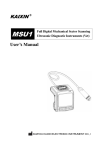
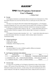
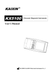
KAIXIN ®
KX5200
Full Digital Ultrasonic Diagnostic
Instruments (Vet)
User’s Manual
XUZHOU KAIXIN ELECTRONIC INSTRUMENT CO., LTD.
Full digital ultrasonic diagnostic instruments (Vet)
User’s Manual
V1.01
Information for Users
Users shall carefully read through this manual and fully understand the text before operating the
equipment. This manual shall be placed easy of access for future reference; otherwise it may cause instrument
damage or person injury.
Intellectual Property Information
Xuzhou Kaixin Electronic Instrument Company Ltd. (hereinafter referred to as Kaixin) has the copyright
of this user’s manual and reserves the right to keep it confidential. This user’s manual shall be used for the
sole purpose of operation, maintenance and servicing of Kaixin’s products.
This user’s manual and intellectual property right (including copyright) herewith included is property of
Kaixin. No persons may use, disclose or allow a third party to obtain by any means any of the information
contained herein without prior written consent of Kaixin. No persons may reproduce this user’s manual, in
whole or in part, including but not limited to photography, photocopy, reprint or translation into any other
language without prior written consent of Kaixin.
This is registered trade mark of Kaixin Company.
Kaixin is the sole authority for the interpretation of this user’s manual.
Kaixin may revise this manual without prior notice.
Kaixin may revise its technical process without prior notice.
Kaixin may modify specifications of the product without prior notice.
Liability and Disclaimer Statement
1. This user’s manual contains warnings for predictable dangers. Users shall also exercise care at any time
to be aware of the dangers unforeseen in this manual. Kaixin shall not be liable for the damages and
losses arising out of neglecting to follow the operation instructions herein described.
2. This user’s manual shall be furnished with the machine so that operating and managerial personnel can
refer to it any time as necessary. Once the managerial personnel of the system changes, it shall hand
over this user’s manual.
3. Medical personnel qualified with professional qualifications only to use this system.
4. This product is intended to provide clinical diagnostic data for the doctor. The doctor in charge of the
diagnosis shall be responsible for the diagnostic process. Kaixin shall not be liable for any problems
arising out of the process.
5. User shall be fully responsible for the maintenance and management of this product after purchasing this
product.
6. Do not modify this equipment without authorization of the manufacturer.
7. Deal with the exhausted product according to the local statute.
8. Kaixin shall not be liable for the safety, reliability and operational state of the product in case of the
following conditions:
(1) Unauthorized components are assembly, stretching, readjustment;
(2) Users fail to properly operate the equipment in accordance with the requirements specified in this
user’s manual.
9. The maintenance and servicing of product shall be performed by the trained engineer or by Kaixin
Electronic Instrument Company Ltd.
Product Information
Issue date: June 15, 2011
Version: V1.02
F-1
Full digital ultrasonic diagnostic instruments (Vet)
User’s Manual
V1.01
Limited warranty
Repair Service
1. Kaixin offers Type B-ultrasound lifetime warranty and charge free repair service from the day of
purchasing the equipment: eighteen months for main unit and typical configured probe, six months
for other components.
2. The company will not assume free warranty for the following situation:
1) Malfunction or damage arising from failing to comply with the instructions of the User’s
Manual;
2) Malfunction or damage caused by falling during moving after purchased;
3) Warranty is expired;
4) Malfunction or damage due to human factors;
5) Damage or malfunction caused by disassembling and assembling, alteration and repair without
the consent of the company;
6) Damage caused by force majeure (like abnormal power supply, fire, flood, lightning strike,
earthquake etc.);
7) Damage or malfunction caused by use of unqualified ultrasonic coupling gel;
8) Damage or malfunction caused by use of probe not provided by our company;
3. The company will offer repair service for instrument out of warranty, but additional fees of materials
and repair service will be charged.
4. The customer can repair the instrument out of warranty by themselves, and if necessary, the
company can provide circuit diagram and components under customers’ request.
Return of Goods
Follow the procedure below if you need to return the purchased equipment:
To obtain the right to return the goods, contact local dealer of Kaixin Company, indicating serial
number of main unit, this number is located on the nameplate of main unit. Please mark the product model,
the serial number of main unit and reason to return the product.
Manufacturer’s Information
Xuzhou Kaixin Electronic Instrument Co., Ltd.
Kaixin Mansion, C-01, Economic Development Zone, Xuzhou, Jiangsu, China.
Zip Code: 221004
Tel: +86-516-87732932
87733758
Fax: +86-516-87732932
87792848
Website: http://www.kxele.com
E-mail: [email protected]
Instructions concerned
For the changes of appearance, this manual is subject to change without further notice!
F-2
Full digital ultrasonic diagnostic instruments (Vet)
User’s Manual
V1.01
Safety Cautions
1. Warning Symbols and Definitions
The following warning symbols are used in this manual to indicate safety level and other important
items. Please remember these symbols and understand the meaning as you read this user’s manual. These
symbols convey specific meanings as detailed in the table below:
Symbols & Words
Connotation
Warning
Indicates an imminent danger that may result in personal death or serious
injury if not avoided.
Indicates a potential danger that may result in personal injury if not avoided.
Attention
Indicates a potential danger or unexpected use condition that may result in
light injury or property loss or affecting the use if not avoided.
Danger
Indicates that make sure refer to relevant contents in this manual.
2. Safety Symbols
Symbols
Meaning
Symbols
Meaning
Type B applied part
Keep dry
Power supply indication
Fragile
DC Power
Stacking limit by number
Follow instructions for use
Temperature limits
Up
Humidity limitation
Marking for the separate collection of
electrical and electronic equipment
Atmospheric pressure limitation
Symbol for the marking of electrical and electronics devices according to
Directive 2002/96/EC. The device, accessories and the packaging have to be
disposed of waste correctly at the end of the usage. Please follow Local
Ordinances or Regulations for disposal.
F-3
Full digital ultrasonic diagnostic instruments (Vet)
User’s Manual
V1.01
Contents
Chapter One Technical Specifications………………………………………………………………1
Chapter Two System Outline and Structure………………………………………………………2
2.1 Structure composition of the instrument……………………………………………………2
2.2 Components name……………………………………………………………………………2
2.3 Parts of the probe……………………………………………………………………………2
2.4 Function keys description………………………………………………………………….. 2
Chapter Three System Configuration………………………………………………………………3
Chapter Four Operation Condition………………………………………………………………3
Chapter Five System Installation and Check…………………………………….……………4
5.1 System installation…………………………………………………………………………4
5.2 Probe installation…………………………………………………………………………6
5.3 Install/dismantle the battery………………………………………………………………6
5.4 Shutter release installation……………………………………………………………………7
5.5 Video recorder installation……………………………………………………………………7
5.6 Connect to the mouse…………………………………………………………………………7
5.7 Connect to power……………………………………………………………………………7
5.8 Probe check before and after operation……………………………………………………8
5.9 Main unit check before and after operation………………………………………………8
5.10 System reset……………………………………………………………………………………8
Chapter Six
Functional Operation………………………………………………………………..9
6.1 Startup and Shutdown…………………………………………………………………………9
6.2 System Functions Setting……………………………………………………………………9
6.2.1 Time Setting………………………………………………………………………………9
6.2.2 TV Mode Setting…………………………………………………………………………9
6.2.3 Energy Saving Setting………………………………………………………………………9
6.2.4 Characters Brightness Setting………………………………………………………………9
6.2.5 Hospital Name Setting……………………………………………………………………9
6.2.6 Key Sound Setting………………………………………………………………………10
6.2.7 Compression Curve Setting…………………………………………………………………10
6.2.8 Chinese-English Setting……………………………………………………………………10
6.3 Mode selection………………………………………………………………………………10
6.3.1 B Mode……………………………………………………………………………………10
6.3.2 B/B Mode…………………………………………………………………………………10
6.3.3 4B Mode……………………………………………………………………………………10
6.3.4 B/M Mode…………………………………………………………………………………11
6.3.5 M Mode…………………………………………………………………………………11
6.4 Image Quality Adjustment………………………………………………………………11
6.4.1 Brightness and Contrast Adjustment………………………………………………………11
6.4.2 Total Gain Adjustment……………………………………………………………………11
6.4.3 Near Field Gain Adjustment………………………………………………………………11
6.4.4 Far Field Gain Adjustment………………………………………………………………11
6.4.5 Dynamic Range Adjustment………………………………………………………………11
6.4.6 Frequency Adjustment (Frequency conversion)…………………………………………11
Full digital ultrasonic diagnostic instruments (Vet)
User’s Manual
V1.01
6.4.7 Focus Adjustment and Control……………………………………………………………12
6.4.8 Frame Correlation Adjustment……………………………………………………………12
6.4.9 Image Post-process Adjustment……………………………………………………………12
6.4.10 Edge Enhancement Adjustment……………………………………………………………12
6.5 Image Control…………………………………………………………………………………12
6.5.1 Magnification Selection……………………………………………………………………12
6.5.2 Depth Range Selection and Depth Enhancement………………………………………12
6.5.3 Local Zoom and Local Additive Color……………………………………………………12
6.5.4 Image Left/right Reverse……………………………………………………………………12
6.5.5 Image Up/down Reverse……………………………………………………………………13
6.5.6 Image Negative……………………………………………………………………………13
6.5.7 Color Selection………………………………………………………………………………13
6.5.8 Scan Range (Angle/Width Change)……………………………………………………13
6.5.9 Image Freeze/Unfreeze……………………………………………………………………13
6.6 Puncture guide and lithotripsy positioning line…………………………………………13
6.7 Body Mark and Probe Mark………………………………………………………………13
6.8 Image storage and recall……………………………………………………………………14
6.8.1 Save image…………………………………………………………………………………14
6.8.2 Open image…………………………………………………………………………………14
6.9 Single dump and mass dump…………………………………………………………15
6.10 Delete the image………………………………………………………………………16
6.11 Image review………………………………………………………………………………16
6.12 Cine loop…………………………………………………………………………………16
6.13 Text Input…………………………………………………………………………………16
Chapter Seven
General Measurement……………………………………………………………18
7.1 Distance Measurement ………………………………………………………………………18
7.2 Fat thickness Measurement………………………………………………………………18
7.3 Circumference/Area/Volume Measurement…………………………………………………18
7.4 Slope/Heart rate/Cycle Measurement………………………………………………………19
Chapter Eight Obstetric Measurement…………………………………………………………20
8.1 Measurement and Calculation items………………………………………………………20
8.2 Measurement of GA and EDC………………………………………………………………20
8.3 Measurement of Swine’s lean percentage…………………………………………………21
8.4 Obstetric report …………………………………………………………………………..21
8.5 Measurement items………………………………………………………………………..21
Chapter Nine
System Maintenance…………………………………………………………22
9.1 Maintenance by users………………………………………………………………………22
9.1.1 System cleaning and disinfection…………………………………………………………22
9.1.2 Use and maintenance for the charging battery………………………………………………23
9.2 Troubleshooting………………………………………………………………………………25
9.3 Periodic Safety Check………………………………………………………………………25
Chapter Ten
Storage and Transportation………………………………………………………26
Chapter Eleven Safety Classification……………………………………………………………26
Full digital ultrasonic diagnostic instruments (Vet)
Chapter One
User’s Manual
V1.01
Technical Specifications
1.1 Technical Data
1. Gray scale: 256
2. Monitor: 5.7” LCD
3. Adapter ratings: 100-240V~, 50-60Hz, 70VA (model: MW125RA1203F01)
4. Output of adapter: DC12V 3.0A
5. Main device rating: DC12V 3.0A
6. Main Unit Size: approx. 155×180×80mm3 (L×W×H)
7. Weight of main unit: approx. 1.1kg (excluding accessories)
1.2 Primary Functions
1. Mode conversion function.
2. Magnification conversion function.
3. Frequency conversion function.
4. Frame correlation function.
5. Image post-process function.
6. Edge enhancement function.
7. Image freeze/unfreeze.
8. Depth range selection function.
9. Depth heighten/pan function.
10. Color display function.
11. Local zooming.
12. Angle/width change.
13. Adjustment and display of near field, far field, total gain and dynamic range.
14. Single-point, multi-point focusing.
15. Image storage.
16. Vertical, horizontal reverse and B/W conversion.
17. Case information, image annotation and auto time display.
18. Body marks.
19. Measurement of distance, fat thickness, circumference, area, volume, slope, heart rate and cycle.
20. OB software package including 27 tables about 8 kinds of animals, automatic
calculation of GA and EDC.
21. Puncture guide.
22. Cine loop.
23. PAL-NTSC Conversion.
24. Energy saving.
25. Chinese-English Switch.
26. Obstetric report.
1
Full digital ultrasonic diagnostic instruments (Vet)
Chapter Two
User’s Manual
V1.01
System Outline and Structure
2.1 Structure composition of the instrument
KX5200 full digital ultrasonic diagnostic instruments (Vet) are composed of main unit, probe and display,
etc.
2.2 Components name
Fig. KX5200 main unit sketch map
2.3 Parts of the probe (Take 6.5MHz animal transrectal linear array probe for example)
1
2
3
Fig. Parts name of 6.5MHz animal transrectal linear array probe
Function
To convert electric signal to ultrasonic signal based on principle of converse
piezoelectric effect. The ultrasonic signal, after entering the human body, is
(1) Acoustic lens
reflected as echo wave and converted to electric signal again. The acoustic
lens is on the probe surface. Supply ultrasonic coupling gel to the acoustic
lens surface when performing ultrasonic diagnosis.
(2) Cable
To connect the probe to the probe connector.
(3) Probe connector
To connect the probe to ultrasonic diagnostic system.
Name
2.4 Function keys description
SN.
Function keys
1
Real-time mode function
Freeze mode function
Mode Selection
Text Input
2
Enter Confirm menu
3
Main-menu / Cine loop
4
Freeze/Unfreeze
5
Direction Keys
6
Quit
7
Power switch
2
Full digital ultrasonic diagnostic instruments (Vet)
Chapter Three
User’s Manual
V1.01
System Configuration
3.1 Typical configuration
1. Main unit
1 unit
2. 6.5MHz animal transrectal linear array probe 1 PC
3. Power adapter
1 PC
4. Internal battery
2 PCS
5. Charger
1 PC
6. Support bracket
1 PC
7. Arm-band
1 PC
8. Straps
2 PCS
9. Leather bag
1 PC
10. Shutter release
1 PC
3.2 Optional parts
1. 3.5 MHz convex array probe
2. 4.0 MHz convex array transrectal probe
3. 5.0 MHz micro-convex probe
4. 6.5 MHz intra-cavity probe
5. 7.5 MHz high frequency linear array probe
6. Video recorder P93W-S
7. Mouse
8. Probe holder
9. Plastic seal box
Chapter Four
Operation Condition
4.1 Power supply
Adapter ratings: 100-240V~, 50/60Hz, 70VA
Adapter model: MW125RA1203F01
Output of adapter: DC12V 3.0A
Main device rating: DC12V 3.0A
4.2 Operation Environment
Ambient temperature: 10℃-40℃;
Relative humidity: 30%-75% (without condensation);
Atmospheric pressure: 700hPa-1060hPa.
Altitude: < 2000 m;
Overvoltage: Overvoltage CategoryⅡ.
4.3 Storage and Transport
Ambient temperature: -20℃-55℃;
Relative humidity: 30%-93% (without condensation);
Atmospheric pressure: 700hPa-1060hPa.
Attention: The mains voltage is varies with different countries or regions.
Warning: Avoid using this equipment with high frequency operational equipment, or
danger may occur.
Danger: Do not use this equipment where flammable gas (such as anesthetic gas,
oxygen or hydrogen) or flammable liquid (such as alcohol) are present. Failure to do so
may result in explosion.
Attention: System should be avoided using in following environments:
1. Moist
2. Rain
3. Thunderstorm weather
4. No ventilation
5. Close to heat source
6. Direct sunlight
7. Dramatic temperature change
8. Poisonous gas
9. Corrosive gas
10. Strong shock
11. Strong electromagnetic field (e.g. MRI)
12. Radiation (e.g. X-ray, CT)
13. Defibrillators or short wave therapy equipment
3
Full digital ultrasonic diagnostic instruments (Vet)
Chapter Five
User’s Manual
V1.01
System Installation and Check
Warning: To avoid the risk of electric shock, this equipment must only be connected to a
supply mains with protective earth.
Warning:
1. If breakers and fuse of the mains power socket are identical to those of this system, and they
are used to control the current for equipment like life support system, the system shall not
be connected to such power supply socket as it may cause breaker or fuse to trip and cut off
the power supply to the entire premise in case of malfunction or over current or transient
current generated at power-on with this ultrasonic system.
2. All plugs of instruments of this system shall be connected into the power socket with
protectively earth on the wall and the socket must meet the requirement of power rating of
instrument. Multiple portable socket-outlets can not be used for the system.
3. Equipment that connects the signal input part or signal output part must only connect the
accessories authorized in this manual, and connect the equipment that complies with the
respective IEC standards(IEC 60950 for data processing equipment and IEC 60601-1 for
medical equipment). If in doubt, consult the technical service department or your local
representative.
4. When this system is installed or used around patient, try to avoid the patient touching the
system. If system is with some unknown defects, it may cause danger of electric shock.
5. If the integrity of the external protective conductor in the installation or its arrangement is
in doubt, equipment shall be operated from its internal electrical power source.
Warning:
1. When instrument works abnormally, do stop working, turn off the power and check the
reason, then contacts the KAIXIN Company about it.
2. Operator in contact with the input/output interfaces can not touch patients at the same time.
3. Turn off power and pull out of the plug from socket after each ultrasonic diagnostic operation.
4. It is forbidden to drag and press the power and probe cables emphatically; regularly inspect
whether there is pull-apart and bareness, if there is the phenomena like this, turn off power
supply immediately, stop using it and change it for new one.
5. It is forbidden to load and unload the probe or move the instrument in galvanic to avoid
danger of safety.
6. Pull out of the plug from socket after operation in thunderstorm weather to avoid the
instrument being damaged by lightening.
7. If the temperature changes greatly in short time will cause vapor recovery inside of
instrument, the case may damage the instrument.
8. The instrument is switched completely only by disconnecting the power supply from the wall
socket.
5.1 System installation
Please carefully read through and fully understand the use-method before installing the system, and
check the goods for its completeness according to the packing list furnished. This system provides the
following several usages, for the user to select:
4
Full digital ultrasonic diagnostic instruments (Vet)
User’s Manual
V1.01
1. Place the instrument on a desktop to use
_
As shown in fig, insert the support bracket from the back of the instrument, place the instrument on a
desktop; adjust the angle of the support bracket to adjust the screen visual angle.
2. Instrument fixed in the arm to use
Attention: when using the arm-band, if allergy, please consult a doctor immediately and
increase protective measures (e.g. Wear gloves before use).
_
_
a. Lock the arm-band as figures from the back of the instrument;
b. Extend your arm into the arm-band according to arrow direction, or disconnect the arm-band to
put on your arm, the long end through the back ring.
c. Strain the arm-band and stick it firmly on the Velcro.
3. Instrument hanging on the chest to use
a. Take out the attached straps; install the
straps on the rings of main unit as fig
shown;
b. Adjust the strap length, the front strap hung
on the neck, the back strap fixed on the
waist, two straps can also adjust to similar
length to meet the requirements of the
screen visual angle, while hanging around
the neck to use.
4. Instrument places on the leather lag and hangs on the chest to use
Installation:
a. Take out the instrument and accessory, install the probe;
b. The probe passes through the oval hole of the leather bag, and
put the instrument into the leather lag;
c. Install the straps on the rings of leather bag as fig shown;
d. Adjust the strap length, the one hung on the neck, the other
one fixed on the waist, you can also use a strap around your
neck or diagonal used in your shoulder.
The benefits of using this method:
a. Self-built darkroom for the strong-light environments.
b. The protection of leather bag can avoid collisions and
pollution in the use process.
5
Full digital ultrasonic diagnostic instruments (Vet)
User’s Manual
V1.01
5.2 Probe installation
Danger: Use together with flammable anaesthetic, it may result in explosion.
Attention: Probe is highly sensitive to shake, be used with caution. About probe’s use
and cleaning, the details see the relevant sections.
Warning:
1. The Kaixin ultrasonic probe shall be connected to the dedicated Kaixin ultrasonic system
only. Select proper probe model according to the relevant instructions of ultrasonic
diagnostic system.
2. Check the ultrasonic probe and connecting cable after diagnostic operation. Use of
defective probe may cause electric shock.
3. Do not knock or bump the probe, or it may be damaged and cause electric shock.
4. Unauthorized disassembly of the probe shall be prohibited as it may cause electric shock
hazard.
Attention:
1. Turn off the ultrasonic system before disconnecting the probe. Disconnecting the probe
with system power on may damage the system or probe.
2. Before disconnecting the probe, place the cable and probe on a stable and leveled position
so that the probe may not be damaged or injury person by unexpected fall.
3. Freeze the instrument when instrument is start-up without operation to increase of service
life of probe.
4. Repeat available machine time should be more than 5 minutes to avoid turn on/off power
supply in short time.
5.2.1 Probe connection
Warning: Before connecting or using the probe, make sure that the probe, connecting
cable and connector are in normal condition (free of cracks or drop). Use of defective
probe may cause electric shock.
Insert the probe connector into the probe socket at the back of the main unit;
5.2.2 Probe disconnection
Socket screwdriver
Turn off the system, and use
probe screwdriver to remove the
probe with figure’s method and
instructions.
Button position on both side of socket
According to arrow
direction,gently insert the socket
screwdriver, then button up the
button position on both side of the
socket with your fingers,you can
remove the probe socket.
5.3 Install/dismantle the battery
1. Install battery
Put the battery into battery storage of main unit; cover the “Upper cover of battery storage” into the
corresponding position, and then toggle the push button in the opposite direction, lock the “Upper cover of
battery storage”.
2. Dismantle battery
According to the direction of the arrow, toggle “Push button of battery storage”, removed “Upper
cover of battery storage” as shown in figure, take out the battery.
6
Full digital ultrasonic diagnostic instruments (Vet)
User’s Manual
V1.01
Upper cover of battery storage
Battery
Push button of battery storage
Fig. Install, dismantle the battery
5.4 Shutter release installation
Install shutter release to shutter release interface (Freeze interface) as shown in the figure.
In the operation, you can
"freeze" or "unfreeze" images
using shutter release.
Shutter release
5.5 Video recorder installation
1. Turn off the system, connect the equipotential terminal ( ) of the video recorder to the earthing;
2. Connect one end of the video connection line to the video recorder and the other end to the video
output interface on the left of main unit;
3. Insert one end of power plug (jack) of the video recorder to the power input socket of the video
recorder, the other end to the power supply socket.
5.6 Connect to the mouse
Connect the mouse to USB interface on the right side of the main unit.
5.7 Connect to power
1. Connect to the power adapter
Insert the output plug of adapter into DC power input interface, which is on the left of main unit.
2. Connect to the main power supply
Insert the power plug (jack) furnished with the machine into power input socket of the power adapter,
the other end to the mains socket-outlet. The instrument uses three-core power supply. It connects
with the protective earth line when power plug inserts into its socket.
Warning:
1. Appliance coupler is intended to be used as disconnecting device. please keep appliance
coupler easily reached by the operator and use appliance coupler as disconnecting device.
2. The device should be used only with power adapter provided by Kaixin Company.
3. To avoid damaging power adapter or harming people by unexpected fallen, make sure the
power adapter is placed on the leveled desk.
Warning: the operator must not touch SIP/SOP and patient simultaneously.
7
Full digital ultrasonic diagnostic instruments (Vet)
User’s Manual
V1.01
5.8 Probe check before and after operation
Before and after ultrasonic diagnosis to check if there are any exceptionally on the surface of the probe
or cable jacket, such as peeling, cracks, bulge, or if the acoustic lens is reliable, disinfected or cleaned.
5.9 Main unit check before and after operation
5.9.1 Inspection before start-up
Check the following items before starting the machine:
1. The temperature, humidity and atmospheric pressure shall meet the requirements of operation
condition.
2. No condensation occurs.
3. No distortion, damage or contamination on system and peripheral. Clean the parts as specified in
relevant sections, if the contaminant is present.
4. Examine the control panel, LCD screen and enclosure to ensure they are in good working condition
and free of abnormity (such as cracks and loosened screws).
5. No damage on power cable, and hard up on its connection.
6. Check probe and its connections to ensure they are free of abnormity (such as scuffing, drop-off or
contamination). If the contaminant is present, clean, disinfect the contaminated objects as specified
in relevant sections.
7. No barriers around the intake of equipment.
8. See to it that probe has been cleaned, disinfected and sterilized; else dispose it as specified in relevant
sections.
9. Check all the ports of the machine for possible damage or blockage.
10. Clean the field and environment.
5.9.2 Inspection after start-up
Check the following items after starting the machine:
1. No abnormal voice, strange smell and overheating appear.
2. Check the machine to ensure a normal start-up: The power indication light is on and startup picture is
shown on the screen. The machine will be then automatically set in B mode.
3. Check the acoustic lens for abnormal heat when the probe is in use. This can be done by hand
touching the probe to feel the temperature of the lens.
4. Check the image to ensure trouble-free display (no excessive noise or flicker).
5. Check the control panel to ensure normal operation condition.
6. Check the instrument to ensure that the phenomenon of local high temperature will not appear.
Warning: Only use the coupling gel that in accordance with MDD regulations.
Attention: If the overheat acoustic lens is placed on the patient’s skin, heat injury may
occur.
Attention: Thoroughly clean the coupling gel on the probe surface each time after
ultrasonic operation, or the coupling gel may become hardened on the acoustic lens of the
probe, deteriorating quality of image.
5.10 System reset
In case of abnormal screen display or no-working for system operation, try to restart the system by
turning on/off the main unit power.
8
Full digital ultrasonic diagnostic instruments (Vet)
Chapter Six
User’s Manual
V1.01
Functional Operation
6.1 Startup and Shutdown
In shutdown status, press key, machine starts up, power indicator lights.
In startup status, press key, machine shuts down, power indicator goes out. Please note that when
shut down the machine, the time of pressing key is a rather long than normal pressing key.
6.2 System Functions Setting
6.2.1 Time Setting
1. Press key to enter main-menu and press direction keys
to move cursor to “Preset”;
2. Press direction keys
to enter setting interface;
3. Press direction keys
to select “Minutes, Hours, Day, Month and Year”;
4. When setting minutes, hours, day, month and year, press direction key to increase value or press
direction key to decrease value;
5. Press key to confirm the time setting and quit setting interface.
6.2.2 TV Mode Setting
1. Press key to enter main-menu and press direction keys
to move cursor to “Preset”;
2. Press direction keys
to enter setting interface;
3. Press direction keys
to move symbol “<” to point to “TV mode”;
4. Press direction keys
to realize TV mode conversion between PAL and NTSC;
5. Press key to quit setting interface.
6.2.3 Energy Saving Setting
1. Press key to enter main-menu and press direction keys
to move cursor to “Preset”;
2. Press direction keys
to enter setting interface;
3. Press direction keys
to move symbol “<” to point to “Sleep”;
4. Press direction keys
to select energy saving time among 1~99 minutes or select “Off”;
5. Press key to quit setting interface.
6.2.4 Characters Brightness Setting
1. Press key to enter main-menu and press direction keys
to move cursor to “Preset”;
2. Press direction keys
to enter setting interface;
3. Press direction keys
to move symbol “<” to point to “Font Bright”;
4. Press direction keys
to select characters brightness among 160, 192, 224 and 255;
5. Press key to quit setting interface.
6.2.5 Hospital Name Setting
1. Press key to enter main-menu and press direction keys
to move cursor to “Preset”;
2. Press direction keys
to enter setting interface;
3. Press direction keys
to move symbol “<” to point to “Hospital”;
4. Press key, the cursor is located above “NAME”; at the same time characters input menu will be
shown at the bottom of the screen:
Caps 0 1 2 3 4 5 6 7 8 9 a b c d e f g h
Shift i j k l m n o p q r s t u v w x y z
Press direction keys or operate mouse to move cursor to point to Caps, and then press key or
click left mouse to achieve capital and small letter conversion; If the cursor point to Shift, press key
9
Full digital ultrasonic diagnostic instruments (Vet)
User’s Manual
V1.01
or click left mouse again to achieve the conversion between the letter and punctuation;
5. Press direction keys to choose “numbers” or “characters” and press key to confirm; Or operate
mouse to click “numbers” or “characters” to input;
6. If need modify the content, press key to quit the character input menu, press direction
keys
to delete input content; press key again to retype;
7. Press key to save this setting and quit setting interface.
6.2.6 Key Sound Setting
1. Press key to enter main-menu and press direction keys
to move cursor to “Preset”;
2. Press direction keys
to enter setting interface;
3. Press direction keys
to move symbol “<” to point to “Key Sound”;
4. Press direction keys
to select between “On” and “Off”;
5. Press key to quit setting interface.
6.2.7 Compression Curve Setting
1. Press key to enter main-menu and press direction keys
to move cursor to “Preset”;
2. Press direction keys
to enter setting interface;
3. Press direction keys
to move symbol “<” to point to “Compression Curve”;
4. Press direction keys
to select compression curve among “00” –“07”;
5. Press key to quit setting interface.
Note: If use 3.5MHz probe, it is recommended to choose 05 or 06; if use 5.0MHz probe,
recommend choose 03 or 04; if use 7.5MHz probe, recommend choose 00 or 01; if use
6.5MHz probe, recommend choose 01 or 02.
6.2.8 Chinese-English Setting
1. Press key to enter main-menu and press direction keys
to move cursor to “Preset”;
2. Press direction keys
to enter setting interface;
3. Press key to switch between Chinese and English;
4. Press key to quit setting interface.
6.3 Mode selection
In real-time mode, press key repeatedly to realize mode switching of B, B/B, 4B, B/M and M.
6.3.1 B Mode
B mode is a basic operation mode after startup and a single-framed B mode image is displayed.
6.3.2 B/B Mode
1. In real-time mode, press key to enter B/B mode.
2. B/B image switch. Press key to enter main-menu and press direction keys
to move the
cursor to “B/B Mode” and then press direction keys
to switch image display. Or right click
mouse to switch image display, the selected image is activated and the other one is frozen.
3. In real-time mode, press key to exit B/B mode.
6.3.3 4B Mode
1. In real-time mode, press key to enter 4B mode.
2. 4B image switch. Press key to enter main-menu and press direction keys
to move the cursor
to “4B Mode”, then press direction keys
to switch display among four images; or right click
mouse to switch display among four images, the selected image is activated and the other three are
frozen.
3. In real-time mode, press key to exit 4B mode.
10
Full digital ultrasonic diagnostic instruments (Vet)
User’s Manual
V1.01
6.3.4 B/M Mode
1. In real-time mode, press key to enter B/M mode.
2. Change of scan mode. Press key to enter main-menu and press direction keys
to move
cursor to “M Mode” and then press direction keys
to change the M ultra-scan mode. Or right
click mouse to realize the change of scan mode.
3. Move sample line. Press key to quit the current using status for direction keys. Press direction
keys to move sample line.
4. In real-time mode, press key to exit B/M mode.
6.3.5 M Mode
1. In real-time mode, press key to enter M mode.
2. Change of M-scan mode: Press key to enter main-menu and press direction keys
to move
cursor to “M Mode” and then press direction keys
to change the M ultra-scan mode. Or right
click mouse to realize the change of scan mode.
3. Change of M speed: Press key to enter main-menu and press direction keys
to move cursor
to “M Speed” and then press direction keys
to select the eight kinds of scan speed. Or left click
mouse to switch M speeds.
4. In real-time mode, press key to exit M mode.
6.4 Image Quality Adjustment
6.4.1 Brightness and Contrast Adjustment
In the startup default status, press freeze key to unfreeze, press key to quit the current using status,
the adjustment bars of brightness and contrast will be displayed on the screen by pressing direction
keys
, adjust them according to actual need. Press direction key to increase brightness and contrast,
direction key to decrease them; press direction keys
to select brightness or contrast adjustment.
Note: If direction keys
cannot be adjusted when adjust brightness in normal operation
mode, must be exit current operating condition of direction keys.
6.4.2 Total Gain Adjustment
In real-time mode, press key to enter main-menu and press direction keys
to move cursor to
“Gain: ” in the display area. Press direction key to increase image total gain and direction key to
reduce total gain so as to control the total gain of the entire image.
6.4.3 Near Field Gain Adjustment
In real-time mode, press key to enter main-menu and press direction keys
to move cursor to
“Near: ” in the display area. Press direction key to increase near field gain and direction key to reduce
near field gain so as to control the gain in near field region.
6.4.4 Far Field Gain Adjustment
In real-time mode, press key to enter main-menu and press direction keys
to move cursor to
“Far: ” in the display area. Press direction key to increase far field gain and direction key to reduce far
field gain so as to control the gain in far field region.
6.4.5 Dynamic Range Adjustment
In real-time mode, press key to enter main-menu and press direction keys
to move cursor to
“Dyn: ” in the display area. Press direction key to increase the value of dynamic range and direction
key to decrease the value of dynamic range so as to control the dynamic range of the entire image.
6.4.6 Frequency Adjustment (Frequency conversion)
In real-time mode, press key to enter main-menu and press direction keys
to move cursor to
11
Full digital ultrasonic diagnostic instruments (Vet)
User’s Manual
V1.01
“Freq.” in the display area. Press direction keys
to realize frequency conversion.
6.4.7 Focus Adjustment and Control
In real-time mode and in B, B/B or 4B mode, press key to enter main-menu and move cursor to “F.
Num” and then press direction keys
to choose from the four focus modes of stage 1(Full process
dynamic focus), 2, 3 and 4.
In real-time mode and in B, B/B, 4B, B/M or M mode, press key to quit menu mode, press
direction keys
again to move the focus up and down.
Note: In B/M or M mode, only allowed choosing single focus mode.
6.4.8 Frame Correlation Adjustment
In real-time mode, press key to enter main-menu and press direction keys
to move cursor to
“Avg” in the display area. Press direction keys
to realize four levels of frame correlation.
6.4.9 Image Post-process Adjustment
In real-time mode, press key to enter main-menu and press direction keys
to move cursor to
“IP” in the display area and then press direction keys
to obtain corrected image. System default is 2.
6.4.10 Edge Enhancement Adjustment
In real-time mode, press key to enter main-menu and press direction keys
to move cursor to
“Edge” in the display area and then press direction keys
to gain four levels of sharpened images.
System default is 0.
6.5 Image Control
6.5.1 Magnification Selection
In real-time mode, press key to enter main-menu and move cursor to “Zoom” and then press
direction keys
to choose eight kinds of magnification.
6.5.2 Depth Range Selection and Depth Enhancement
In real-time mode, press key to enter main-menu and press direction keys
to move cursor to “Depth”
in the display area and then press direction keys
to select depth, press key to quit depth range
selection.
Note: There is no depth selection function when main unit matching probe which its nominal
frequency greater than or equal to 6.5MHz.
In real-time mode, press key to enter main-menu and press direction keys
to move cursor to
“Upgrade” in the display area and then press direction keys
, “ ” appears on the screen. Press
direction keys or operate mouse to move image up/down or left/right so as to observe the images of
different depth and width. Press key to quit depth heighten/pan status.
6.5.3 Local Zoom and Local Additive Color
In real time mode, press key to enter main-menu and press direction keys
to move cursor to
“Local Zoom” in the display area and then press direction keys
, a box appears. Press direction keys
or operate mouse to move the box to the position to be enlarged, the selected image be enlarged;
Press key to quit local zoom status.
In the color display, the selected image which by above mentioned operation will be enlarged and
added color.
6.5.4 Image Left/right Reverse
In real-time mode and in B, B/B, 4B or B/M mode, press key to enter main-menu and press
direction keys
to move cursor to “H Rev” and then press direction keys
to realize image
horizontal reverse. Or left click mouse also to realize image horizontal reverse. The image horizontal
reverse is the change of probe scanning direction. The probe scanning direction is indicated by the arrow
12
Full digital ultrasonic diagnostic instruments (Vet)
User’s Manual
V1.01
on the upper left area of the image.
6.5.5 Image Up/down Reverse
In real-time mode, press key to enter main-menu and press direction keys
to move cursor to
“V Rev” and then press direction keys
to realize image vertical reverse.
6.5.6 Image Negative
In real-time mode, press key to enter main-menu and press direction keys
to move cursor to
“Image POS” and then press direction keys
to realize negative function.
6.5.7 Color Selection
In real-time mode, press key to enter main-menu and press direction keys
to move cursor to
“COLOR:” in the display area and then press direction keys
to realize color conversion of eight
colors (including one kind of black and white).
6.5.8 Scan Range (Angle/Width Change)
In real-time B mode, press key to enter main-menu and press direction keys
to move cursor to
“Angle” and then press direction keys
to choose angle/width.(convex array for scanning angle and
linear array for scanning width).
6.5.9 Image Freeze/Unfreeze
In real-time mode, press
key or middle mouse key to freeze the image; in frozen status, press
key
or middle mouse key to unfreeze the image.
6.6 Puncture guide and lithotripsy positioning line
Puncture guide line: In real-time B mode, press key to enter main-menu and press direction
keys
to move cursor to “Puncture” and then press direction keys
to choose line 1, press key
to confirm, two puncture guide lines appear on the screen, press direction keys
to change the angle of
the first puncture guide line, press direction keys
to change the start position of the first puncture
guide line. Press key again to enter main-menu and press direction keys
to move cursor to
“Puncture” and then press direction keys
to choose line 2, press key to confirm, press direction
keys
to change the angle of the second puncture guide line, press direction keys
to change the
start position of the second puncture guide line. Press key to quit the puncture guide status.
Lithotripsy positioning line: In real-time B mode, press key to enter main-menu and press direction
keys
to move cursor to “Puncture:” and then press direction keys
to choose line 3, press key
to confirm, lithotripsy positioning line appears on the screen; At the same time, the measurement depth of
lithotripsy positioning line “+: 0.0mm” is shown at the top right corner, operate the up/down keys to
positioning the depth. Press key to quit.
6.7 Body Mark and Probe Mark
This product contains 27 body marks that are divided into two pages when display. The operation steps
are as follows:
1. In frozen status, press key to enter main-menu and press direction keys
to move cursor to “Body
mark”, press key, body marks will be showed in the image area, press direction keys to change pages;
2. Press direction keys to move to the position of desired body mark, press key to confirm the
selected body mark;
3. Press direction keys or operate mouse to change the probe mark position; press key to change
probe mark direction;
4. Press key to quit body mark and probe mark status;
5. Press
key to quit froze and body mark status.
13
Full digital ultrasonic diagnostic instruments (Vet)
User’s Manual
V1.01
6.8 Image storage and recall
6.8.1 Save image
l Storage to main unit
1. Freeze the image;
2. Press key, a “Save” prompt appears on lower right corner of the screen;
3. Press direction keys
to select the image code need to be saved in the “LOCAL”, such as choose
“003”;
4. Press key to appear “Wait” prompt. After the prompt disappear, the current image is saved in the
frame for coded “003”. The saved image code is preceded with asterisk “*”;
5. Press key to quit saving status and press
key to return to real-time status.
l Storage to U disk
1. Plug U disk;
2. Freeze the image;
3. Press key, a “Save” prompt appears on lower right corner of the screen;
4. Press direction keys
to select the image code need to be saved in the U disk, such as choose “004”;
5. Press key to appear “Wait” prompt. After the prompt disappear, the current image is stored in the
folder for patient number (ID) as folder name in the U disk, and file name is arranged by the selected
saving code that is “4”. If user did not enter the number (ID), the folder name defaults to “USER”;
6. Press key to quit saving status and press
key to return to real-time mode.
Explanation:
1. Each number (ID) corresponds to a folder, the largest storage for each folder is 100 images.
2. Press key, can select “LOCAL” or “U Disk”.
3. If you want to use number (ID) for the folder name, must first input number (ID) and then
store image. Folder name is made up of underline, letters or numbers, without spaces.
6.8.2 Open image
l Open image in the main unit
1. Freeze the image;
2. Continuously press key twice, a “Read” prompt appears on lower right corner of the screen;
3. Press direction keys
to select the image code need to be read out in the “LOCAL”, such as
choose “003*”;
4. Press key to appear “Wait” prompt. After the prompt disappear, the image stored in frame “003*”
is read out;
5. Press key to quit reading status and press
key to return to real-time status.
l Open image in the U disk
1. Plug U disk;
2. Freeze the image;
3. Continuously press key twice, a “Read” prompt appears on lower right corner of the screen;
4. Press direction keys
to select the image code need to be read out in the U disk, such as choose
“004*”;
5. Press key to appear “Wait” prompt. After the prompt disappear, the image stored in frame “004*”
is read out;
6. Press key to quit reading status and press
key to return to real-time status.
Explanation:
1. When reading images, it must choose the image code with “*”.
14
Full digital ultrasonic diagnostic instruments (Vet)
User’s Manual
V1.01
2. If you want to read out the images within the folder identified by number (ID) under the U disk,
must input ID first before reading, then do as the above steps; if did not enter the number (ID),
it would default to read out the images in the “USER” folder under the U disk.
3. If has read out the images in the U disk, also would like to re-read the local image, must
press key to exit this reading status, then press key to choose “LOCAL”, and vice versa.
6.9 Single dump and mass dump
6.9.1 Single dump
l From main unit to U disk
1. Read out the image in the main unit, “Img” with highlight status is displayed on lower right corner of
the screen;
2. Press key, a “Dump” prompt appears on lower right corner of the screen;
3. Press direction keys
to select the image saving code in the U disk, such as choose “005”;
4. Press key, “Dump” prompt disappears, until the “Dump” re-appears, the current image can be
dumped in the frame for coded “005”. The dumped image code is preceded with asterisk “*”;
5. Press key to quit dumping status and press
key to return to real-time status.
l From U disk to main unit
1. Enter the number (ID), after completed it, exit the enter status;
2. Read out the image in the U disk, “Img” with highlight status is displayed on lower right corner of the
screen;
3. Press key, a “Dump” prompt appears on lower right corner of the screen;
4. Press direction keys
to select the image saving code in the “LOCAL”, such as choose “006”;
5. Press key, “Dump” prompt disappears, until the “Dump” re-appears, the current image can be
dumped in the frame for coded “006”. The dumped image code is preceded with asterisk “*”;
6. Press key to quit dumping status and press
key to return to real-time status.
Note: If not enter number (ID), it will select the image within the system default “USER” folder.
The operation steps are 2-6.
6.9.2 Mass dump
l From main unit to U disk
1. Freeze the image, continuously press cine loop key
until enter “PAUSE” status;
2. Press key, “LOCAL -> U Disk Mass Dump?” prompt display at the bottom of the screen;
3. Press key, “Dumping” prompt appears, images are mass dumped under the “DUMP” folder in the
U disk, and the number behind “PAUSE” character is the number of files name of mass dumping.
After finishing mass dumping, return to “PAUSE” status;
4. Press key to quit mass dumping status and press
l From U disk to main unit
1. Plug U disk;
2. Freeze the image, continuously press cine loop key
key to return to real-time status.
until enter “PAUSE” status;
3. Press key twice, “U Disk -> LOCAL Mass Dump?” prompt display at the bottom of the screen;
4. Press key, “Dumping” prompt appears, the number behind “PAUSE” character is the number of
files name of mass dumping. After finishing mass dumping, return to “PAUSE” status;
5. Press key to quit mass dumping status and press
key to return to real-time status.
Explanation:
1. Mass dump, which is dump images from main unit to “DUMP” folder in the U disk; can also
15
Full digital ultrasonic diagnostic instruments (Vet)
User’s Manual
V1.01
dump the images under the “DUMP” folder in the U disk to main unit.
2. If U disk does not have “DUMP” folder, or “DUMP” folder does not have images, or the
images within the “DUMP” folder are not named by digital 1-100, press
key, although the
screen prompt “Dumping”, the image number is not appeared on the right corner of the
screen.
6.10 Delete the image
1. Freeze the image, press key to enter reading or saving image status;
2. Press key to switch “LOCAL” and “U disk”, identified the location “LOCAL” or “U disk” for
file need to be deleted;
3. Press direction key
to select the image code to be deleted, such as “002*”;
4. Press key, the image will be deleted, “*” will automatically disappear;
5. Repeat the 2-3 steps, delete other images;
6. Press
key to return to real-time mode.
Explanation:
If you want to delete the images within the folder identified by number (ID) under the U disk,
must input ID first before deleting, then do as the above steps; if did not enter the number (ID),
it would default to delete the images in the “USER” folder under the U disk.
6.11 Image review
1. Freeze the image, press
key to enter reading or saving image status;
2. Press key to enter the function of “LOCAL” image review, images will be automatically played
by the fixed time interval;
3. Press direction keys
to select the previous or the next image to review;
4. Press key to return to frozen status.
6.12 Cine loop
In real-time mode, the system is always saving the scanned image. The playback images are for a
period time images before freeze.
Freeze the image, continuously press key three times to enter the automatic playback status;
Press key to enter pause status when playing back; Press direction keys
or operate mouse to view
images frame by frame in pause status; Continuously press key three times again to return to automatic
playback status. In the process of saving and playback, relevant data of image frames saved and played are
shown on the lower right corner of the screen.
Press key to return to frozen status.
Press
key unfreeze and quit playback status.
Note: If the images appear abnormal, that is without enough storage time and the images have
not been stored full.
6.13 Text Input
Operation steps:
1. Freeze image;
2. Press key, the cursor is located behind name;
3. Press key again or right click mouse, at the same time characters input menu will be shown at
the bottom of the screen:
Caps 0 1 2 3 4 5 6 7 8 9 a b c d e f g h
Shift i j k l m n o p q r s t u v w x y z
16
Full digital ultrasonic diagnostic instruments (Vet)
User’s Manual
V1.01
Press direction keys or operate mouse to move cursor to point to Caps, and then press key or left
click mouse to achieve capital and small letter conversion; If the cursor point to Shift, press key
or left click mouse again to achieve the conversion between the letter and punctuation;
4. Press direction keys to choose “numbers” or “characters” and press key to confirm; Or operate
mouse to click “numbers” or “characters” to input;
5. After inputting name, press key and then press direction key to move cursor to “ID” and
press key again to input according to Step 4, the number (ID) only be made up of numbers,
letters or underlines;;
6. After inputting ID, press key and press direction keys to move cursor to image area and
press key again to input according to Step 4;
7. If need modify the content, continuously press key twice to quit annotation status, press
direction keys
to select “Clear”, at last press key to clear all noted marks and retype;
8. Press key to quit.
17
Full digital ultrasonic diagnostic instruments (Vet)
Chapter Seven
User’s Manual
V1.01
General Measurement
7.1 Distance Measurement
1. In B, B/B or B/M mode, choose desired image and freeze it, the cursor is located in the “Measure”
position of display area;
2. Press key, the measurement methods are showed in the lower left of the screen, press direction
keys
to choose “Distance”, press key again, the cursor will show “+”;
3. Press direction keys or operate mouse to move the “+” mark to desired position, press key or
click left mouse to set the “+” mark position as the starting point of the measurement;
4. Press direction keys or operate mouse to move the“+” mark to the end point of the measurement. A
lighted dotted line appears between the starting point and the end point as the dashed locus of the
measurement. The measured value is automatically displayed at the built-in mark“+: ----mm” on
the right side of the screen;
5. Press key or click left mouse repeatedly to exchange the starting point and end point of the
measurement;
6. Press key or click right mouse to finish the first measurement;
7. Repeat the steps 3~6 to complete the multi-group data measurement;
8. Continuously press key twice to quit the measurement status;
9. Press direction keys
to choose “Clear” or synchronously click the left and right key of mouse
to clear all marks and data;
10. Press
key or click the middle mouse to unfreeze, clear all marks and data and quit the
measurement status.
7.2 Fat thickness Measurement
1. In B, B|B, B|M or M mode, choose desired image and freeze it, the cursor is located in the
“Measure” position of display area;
2. Press key, the measurement methods are showed in the lower left of the screen, press direction
keys
to choose “Distance”, press key again, the cursor will show “+”;
3. Press key, a dotted line of fat thickness measurement appears in the middle of screen, press
direction keys
or operate the mouse to move the dotted line to desired position, press
direction keys
or operate the mouse to move the“+” mark to the end point of the
measurement, the measured value of fat thickness is automatically displayed at the built-in mark“+:
----mm” on the right side of the screen;
4. Press key or click right mouse to complete the multi-group fat thickness measurement;
5. Press key to return to the status of distance measurement;
6. Continuously press key twice to quit the measurement status;
7. Press direction keys
to choose “Clear” or synchronously click the left and right key of mouse
to clear all marks and data;
8. Press
key or click the middle mouse to unfreeze, clear all marks and data and quit the
measurement status.
Note: Direction keys
cannot work in the fat thickness measurement when connecting
convex array probe.
7.3 Circumference/Area/Volume Measurement
l Circumference/area measurement with trace method
18
Full digital ultrasonic diagnostic instruments (Vet)
User’s Manual
V1.01
1. In B, B/B mode, choose desired image and freeze it, the cursor is located in the “Measure” position
of display area;
2. Press key, the measurement methods are showed in the lower left of the screen, press direction
keys
to choose “Trace”, press key again, the cursor will show “+”;
3. Press direction keys or operate mouse to move the “+” mark to desired position, press key or
click left mouse to set the “+” mark position as the start of the measurement; or click right mouse
to set the “+” mark position as the starting point of the measurement;
4. Press direction keys or operate mouse to move the“+” mark to the end point of the measurement.
At the same time, a locus appears in the direction of operation between the two measurement
marks. The measured circumference value is displayed automatically at the built-in mark “C:
00000mm” on the right part of the screen. Press key or click right mouse to display at the
built-in mark “A: 00000mm2” the value of the measured area formed by measurement line
enclosure;
5. Press key, the measurement methods are showed in the lower left of the screen, continue to
choose “Trace” to measure;
6. Repeat steps 3, 4 to complete the multi-group data measurement;
7. Continuously press key twice to quit the measurement status;
8. Press direction keys
to choose “Clear” or synchronously click the left and right key of mouse
to clear all marks and data;
9. Press
key or click the middle mouse to unfreeze, clear all marks and data and quit the
measurement status.
l Circumference/area/volume measurement with ellipse method
1. In B, B/B mode, choose desired image and freeze it, the cursor is located in the “Measure” position
of display area;
2. Press key, the measurement methods are showed in the lower left of the screen, press direction
keys
to choose “Ellipse”, press key again, the cursor will show “+”;
3. Press direction keys or operate mouse to move the “+” mark to desired position, press key or
click left mouse to set the “+” mark position as the starting point of the measurement;
4. Press direction keys or operate mouse to move the“+” mark to the end point of the measurement, at
the same time the elliptic curve appears; or click middle mouse to appear elliptic curve;
5. Press key, the “
”mark appears on the screen. Hold down or key to change the
minor axis of the ellipse so as to satisfy the test area. The measured values are displayed at the
built-in characters “C: 00000mm, A: 00000mm2, V: 00000 cm3” on the right part of the screen
automatically;
6. Press key again to quit the minor axis status; Press key or repeatedly click left mouse to
exchange the starting point and end point;
7. Press key or click right mouse to finish the first measurement;
8. Repeat the steps from 3 to 7 to complete the multi-group data measurement;
9. Continuously press key twice to quit the measurement status;
10. Press direction keys
to choose “Clear” or synchronously click the left and right key of mouse
to clear all marks and data;
11. Press
key or click the middle mouse to unfreeze, clear all marks and data and quit the
measurement status.
7.4 Slope/Heart rate/Cycle Measurement
The method to measure slope/hear rate/cycle is identical with distance measurement.
19
Full digital ultrasonic diagnostic instruments (Vet)
User’s Manual
V1.01
Note: In B/M mode, if both starting point and end point of the measurement mark fall into the
B-mode area, the value of the “+: ”refers to distance; if starting point and end point of the
measurement mark fall into the M-mode area, the value of the “+: ”refers to depth; if the
starting point and end point are in separate areas, the “+: ”will display “----”sign or invalid
value.
+: denotes depth measured in mm (millimeter)
EF: denotes slope coefficient measured in mm/s (millimeter per second)
HR: denotes heart rate measured in times/minute (times per minute)
T: denotes cycle measured in ms (millisecond)
Attention: The accuracy of software measurement: distance measurement≤1mm;
area measurement≤1mm2; volume measurement≤1cm3; heart rate measurement≤
1bmp; time measurement≤1ms. Due to differences in images obtained by each user in
different times, the actual object for the accuracy of the measurement may be greater
than the above-mentioned values.
Chapter Eight
Obstetric Measurement
8.1 Measurement and Calculation items
Obstetric tables of the system including: 1.BOVINE, 2.EQUINE, 3.OVINE, 4.CANINE, 5.FELINE,
6.GOAT, 7.LLAMA, 8. SWINE, which is reference for doctor.
8.2 Measurement of Gestational Age (GA) and Estimated Date of Confinement (EDC)
Follow the steps below:
1. In B, B/B mode, freeze the desired image, press direction keys
to choose “OB” in the display
area;
2. Press key to display the obstetric measurement animals on the lower part of the screen,
“VETERI Select: 1.BOVINE, 2.EQUINE, 3.OVINE, 4.CANINE, 5.FELINE, 6.GOAT,
7.LLAMA, 8. SWINE”, press direction keys
to select the measurement animal, press key
to confirm, measured parameters of this animal are showed on the lower part of the screen, (for
example, select goat that is, display the types of goat);
3. Press direction keys
to select the measured parameters (for example select goat, this step is to
select the type of goat, press key again to display the measured parameters of goat), press key,
the cursor will show “+”;
4. Press direction keys or operate mouse to move the “+” mark to desired position, press key or
click left mouse to set the “+” mark position as the starting point of the measurement;
5. Press direction keys or operate mouse to move the“+” mark to the end point of the measurement.
At the same time, a lighted dotted line appears between the start and the end as the dashed locus of
the measurement. The measured value is automatically displayed at the built-in mark“+: ----mm”
on the right side of the screen; G.A and EDC value to be displayed in real time in the right area of
the screen;
6. Press key or repeatedly click left mouse to exchange the starting point and end point;
7. Press key or click right mouse to finish the first measurement;
8. Repeat the steps from 3 to 7 to complete the multi-group data measurement;
9. Press key to quit measurement status for this animal;
10. Repeat steps 2 to 9 to complete a variety of animals measurements;
20
Full digital ultrasonic diagnostic instruments (Vet)
User’s Manual
V1.01
11. Press direction keys
to choose “Clear” or synchronously click the left and right key of
mouse to clear all marks and data;
12. Press
key or click the middle mouse to unfreeze, clear all marks and data and quit the
measurement status.
8.3 Measurement of Swine’s lean percentage
% Lean calculation formula uses NSIF formula.
1. In B, B/B mode, freeze the desired image, press direction keys
to choose “OB” in the display
area;
2. Press key to display the obstetric measurement animals on the lower part of the screen,
“VETERI Select: 1.BOVINE, 2.EQUINE, 3.OVINE, 4.CANINE, 5.FELINE, 6.GOAT,
7.LLAMA, 8. SWINE”, press direction keys
to select “8.SWINE”, press key to confirm,
measured parameters of this animal are showed on the lower part of the screen;
3. Press direction keys
to select “2. %Lean”, press key again to confirm, the cursor will show
“+”;
4. Press direction keys
to select “Weight” (range1.0~300.0kg), press key again to
confirm;
5. Measure the fat thickness with distance measurement method, the fat thickness is displayed in real
time in the right area of the screen; measure loin with distance measurement method, the loin is
displayed in real time in the right area of the screen; press key or click right mouse to finish the
loin measurement, the %Lean will be displayed in the right area of the screen;
6. Continuously press key twice to quit the measurement status;
7. Press direction keys
to choose “Clear” or synchronously click the left and right key of mouse
to clear all marks and data;
8. Press
key or click the middle mouse to unfreeze, clear all marks and data and quit the
measurement status.
8.4 Obstetric report
In frozen status, press key to enter main-menu and press direction keys
to move the cursor to
the position “Report”. Press direction keys
to display obstetric report. Press key to exit obstetric
report status.
8.5 Measurement items
1. Items measurable in B mode: distance, fat thickness, circumference, area, volume, gestational age
(GA) and estimated date of confinement (EDC).
2. Items measurable in B/B mode: distance, fat thickness, circumference, area, volume, gestational age
(GA) and estimated date of confinement (EDC).
3. Items measurable in B/M mode: distance or depth, slope, heart rate and cycle.
4. Items measurable in M mode: depth, slope, heart rate and cycle.
5. If the display becomes “----”, it indicates an invalid measurement value.
21
Full digital ultrasonic diagnostic instruments (Vet)
Chapter Nine
User’s Manual
V1.01
System Maintenance
The system maintenance should be performed by the user and service engineer. Users shall be in full
charge of maintenance, repair and operation of the system after purchasing the product.
9.1 Maintenance by users
9.1.1 System cleaning and disinfection
Warning: Turn off the instrument and pull out the power supply wire before cleaning
every instrument of the system. It may cause electric shock if clean the system under
power is on.
Warning: There is no any waterproof device in the system. Do not splash any water or
liquor into the system when cleaning or maintaining; otherwise it will cause
malfunction or electric shock.
Attention:
1. Probe without cleaning, disinfection may become the source of contamination, so
cleaning or disinfection to the probe is very necessary after every ultrasonic diagnosis.
2. To prevent possible infection, it is advisable to wear sterilized gloves when cleaning,
disinfecting the ultrasonic probe.
3. In the process of cleaning and disinfection, avoid probe overheat (exceeding 60℃) as it
may be deformed or damaged under excessive heat.
4. To prevent the infection or the cross infection, the intra-cavity probe surface should be
covered with a condom every time before examination.
5. Do not use the probe packing box to store the probe as the box may become the source of
contamination.
6. The waterproof grade of intra-cavity probe is IPX7, immersion depth from probe’s
acoustic head to the sheath of probe handle; others are IPX4.
1. Clean the probe
(1) Wear sterilized gloves to prevent possible infection.
(2) Clean the probe with sterile water to remove all contaminants. Do not use brush as it may
damage the probe.
(3) Dry the probe with sterilized cloth or gauze after cleaning. Do not dry the probe by heating it.
2. Routinely disinfect the probe
(1) Wear sterilized gloves to prevent possible infection in the process of routine disinfection.
(2) Clean the probe firstly before routine disinfection, and then wipe the probe twice with 75% alcohol.
(3) Clean the probe with sterile water to remove residual chemicals.
(4) Clean the water off the probe surface with sterilized cloth or gauze. Never dry the probe by
heating it.
Warning:
Do not place the ultrasonic probe connector into water or disinfection,
as it may cause electric shock.
3. Periodically disinfect the probe
(1) Wear sterilized gloves to prevent possible infection in the process of periodical disinfection.
(2) Clean the probe firstly before periodical disinfection. 2%glutaraldehyde disinfectant is
recommended for the probe. Immerse the sound head part of the probe (See periodical
disinfection sketch map) in liquid for more than 10 hours for disinfection.
22
Full digital ultrasonic diagnostic instruments (Vet)
User’s Manual
V1.01
Attention:
1. Please carefully read the instructions provided by disinfectant provider about the
disinfection liquid concentration and disinfection method as well as the description of
the dilution method.
2. Glutaraldehyde liquid should use the activator.
(3) Clean the probe with sterile water to thoroughly remove residual chemicals.
(4) Clean the water off the probe surface with sterilized cloth. Never dry the probe by heating it.
Fig. Wrong 6.5MHz probe periodical disinfection Fig. Correct 6.5MHz probe periodical disinfection
Attention:
1. It is a normal phenomenon that color of the acoustic lens may change and color of the
probe label may fade away.
2. To prevent the infection or the cross infection, such cleaning, disinfection for puncture
bracket and probe is very necessary before and after every puncture operation.
3. The regular disinfection times should be minimized as it may lead to degrade of the probe
safety and performance.
4. Clean the probe cable and its connector
(1) Clean the probe cable and its connector with soft, dry cloth.
(2) In case of die-hard blots, clean with soft cloth dipped in moderate detergent and then air-dry it.
5. Clean the LCD screen
Clean the liquid crystal display with dry, soft flax or anti-static LCD clean cloth.
Attention: Do not clean the screen with hydrocarbon detergent for example alcohol etc
or OA equipment cleaning media. These kinds of liquid may degrade the internal function
of the screen.
6. Clean the control panel, shell
Clean the instrument surface with soft, dry cloth or with soft cloth dipped in moderate water
cleaning media to remove the blots, and then dry the instrument with soft, dry cloth or with air.
7. Clean the video recorder
(1) Use the soft dry cloth to wipe the video recorder.
(2) If it is difficult to wipe away the blemish, clean with soft cloth dipped in moderate detergent and
then air-dry it.
9.1.2 Use and maintenance for the charging battery
1. Only use charger and battery (model CNLB-01) provided by KaiXin Company.
2. The output port of adapter plugs into the input port of charger to charge; the minimum charging time
is 3 hours and up to 4 hours. Over-charging or discharging will shorten the battery life; the full
charged battery can be used for 2 ~ 3 hours.
3. Battery is consumable; the battery cycle-life is based on the times of charge and discharge as unit.
When the use time reduced significantly compared with normal conditions, the battery should be
promptly replaced.
4. The excess high or low temperature will affect the charging and discharging performance, and short
the battery life and capacity.
Attention: Battery charger shall meet the requirements of the IEC60601-1 standard.
23
Full digital ultrasonic diagnostic instruments (Vet)
User’s Manual
V1.01
Attention: Battery is consumable; the battery cycle-life is based on the times of charge
and discharge as unit. When the use time reduced significantly compared with normal
conditions, the battery should be promptly replaced.
Attention: A power indicator will appear “X” and glitter continually when the electric
quantity is too low. Connect the main unit to external power supply and recharge the
battery, or turn off the machine to recharge.
Attention: If long-term use exrernal power or do not intend to use the equipment within
such a period of time, please remove the battery, to avoid over-charging or discharging the
battery which will curtail battery life, or to reduce other risk.
Attention: Don’t throw away the exhausted battery anywhere; especially throw it in the
fire. Please deal with it according to local statutes. Use pollution degree II to deal with.
Attention: 1. Do not throw the battery into water or be wet, which will lead to the battery
leakage, explosion or fire;
2. Do not use or store the battery near the heat source, such as fire or heater, which will lead to
the battery leakage, explosion or fire;
3. Do not connect the anode and cathode reversely, which will lead to the battery leakage,
explosion or fire;
4. Do not heat up or throw the battery into fire, which will lead to the leakage, explosion or fire;
5. Do not connect the anode and cathode with any metal or conductor; do not transport or
store the battery together with necklaces, hairpins or other metal objects, which will lead to
the leakage, explosion or fire;
6. Do not hammerblow, throw or mechanically shake the battery, which will lead to the
leakage, explosion or fire;
7. Do not insert the battery with nail or other spiculate objects; do not hammerblow or trample
the battery, which will lead to the leakage, explosion or fire;
8. Do not weld the battery terminal directly, which will lead to the leakage, explosion or fire;
9. Do not disassemble the battery in any way, which will lead to the leakage, explosion or fire;
10. Do not charge the battery near the heat source or extra-hot environment, which will lead to
the leakage, explosion or fire;
11. Do not put the battery into the microwave oven or pressure vessel, which will lead to the
leakage, explosion or fire;
12. Do not mixed use the battery together with one-off battery (such as dry battery), or
different capability or different model or different brand battery, which will lead to the
leakage, explosion or fire;
13. Do not use the abnormal battery with particular smell or abnormal heat or distortion or
turn colors or abnormal phenomena, which will lead to the leakage, explosion or fire;
14. Do stop the charge and pull out the battery from the charger at once if any abnormal
phenomenon happens to the battery, such as particular smell or abnormal heat or distortion
or turn colors. Otherwise, each of above will lead to the leakage, explosion or fire;
15. Do remove the battery from the near fire if any leakage or particular smell happens, which
will lead to the leakage, explosion or fire;
16. If any leakage splash into eye, do not wipe the eye, instead of washing it and get help from
the doctor as soon as possible. Otherwise, the eye will be injured;
17. Do not use the battery in the extremely hot environment, such as hot sunshine or in the car
when it is too hot, because these will catch fire, even worsen its performance and shorten its life;
18. If use the battery beyond the listed environment on the manual, it will worsen its
performance or shorten its life, even lead to extreme heat or explosion or fire.
24
Full digital ultrasonic diagnostic instruments (Vet)
User’s Manual
V1.01
9.2 Troubleshooting
To ensure normal operation, users are recommended to prepare a proper maintenance and regular
examination plan to regularly check on product safety performance. If any abnormity occur, timely contact
International Trade Dept of Kaixin for support.
If the following problems occur on starting up the machine, try to make corrections following the
method in the table. If the problem remains unsolved, contact International Trade Dept of Kaixin for
support.
Trouble
Correction
Power light is off and no screen
display is present when starting the
machine.
1. Check power supply.
2. Check power cable and connector.
3. Check power adapter.
Character and gray scale are
displayed, but no ultrasonic image on
the screen.
Probe is not properly connected. Turn off the power and
reconnect the probe.
Intermittent stripe, snow, or far-field
interference appears on screen.
1. Check power supply.( spark interference present)
2. Check environment.(source of interference around the
machine, such as electric motor, ultrasonic atomizer,
automobile, computer or other interference )
3. Check power plug/socket of the instrument or probe
connectors. They shall be properly contacted.
Image display is not clear.
1. Adjust the total gain, near field, far field.
2. Adjust the brightness and contrast level.
Control panel malfunction
Restart the system by turning off the main unit power.
9.3 Periodic Safety Check
1. The following safety checks should be performed at least every 12 months by a qualified person who
has adequate training, knowledge, and practical experience to perform these tests.
l Inspect the equipment and accessories for mechanical and functional damage.
l Inspect the safety relevant labels for legibility.
l Inspect the fuse to verify compliance with rated current and breaking characteristics.
l Verify that the device functions properly as described in the instructions for use.
l Test the protection earth resistance according to IEC 60601-1: Limit: 0.1Ω.
l Test the earth leakage current according to IEC 60601-1: Limit: NC 500μA, SFC: 1000μA.
l Test the touch current according to IEC 60601-1: Limit: NC 100μA, SFC: 500μA.
l Test the patient leakage current according to IEC 60601-1: Limit: for a.c.: 100μA (B), for d.c.:
10μA (B).
l Test the patient leakage current under single fault condition with mains voltage on the applied part
according to IEC 60601-1: Limit: for a.c.: 500μA (B), for d.c.: 50μA (B).
The leakage current should be never exceed the limit. The data should be recorded in an equipment log.
If the device is not functioning properly or fails any of the above tests, the device has to be repaired.
2. Please clean the plug of power cord at least once a year. Too much dust on plug may cause the fire.
25
Full digital ultrasonic diagnostic instruments (Vet)
Chapter Ten
User’s Manual
V1.01
Storage and Transportation
Storage and Transportation
1. If the instrument is stored over 3 months, take out the instrument from the packing case, connect it to
power supply for 4 hours, and then disconnect the power and place it in the case again following the
direction indicated by arrows on the package. Store the case in the warehouse. Do not pile the case. The
instrument case should have adequate space from ground, walls and ceiling of the warehouse.
2. Environment requirement
Ambient temperature: -20℃-55℃; Relative humidity: 30%-93% (without condensation);
Atmospheric pressure: 700hPa-1060hPa. The warehouse should be well ventilated and free of direct
sunlight and corrosive gas.
3. Shockproof measures have been taken inside the packing case to allow for transport by air, railway, land
and sea. The goods shall not be exposed to poor weather conditions like rain and snow, nor shall the
goods be placed upside down, bumped, knocked or over-stacked.
Chapter Eleven
Safety Classification
1. Classified according to electric shock protection type:
Class I, internally powered equipment
2. Classified according to electric shock protection degree:
Type B applied part
3. Classified according to the degree of protection against ingress of liquid:
Main unit belong to IPX0 equipment
4. Classified according to operation safety in condition of existence of flammable anesthetic mixture with
air or oxygen or nitrous oxide:
It is neither of category AP equipment nor of category APG equipment
5. Classified according to mode of operation:
Continuous operation equipment
6. Classified according to the protection of radio services:
Group I Class A equipment
26
KAIXIN ELECTRONIC
XUZHOU KAIXIN ELECTRONIC INSTRUMENT CO., LTD.
Kaixin Mansion, C-01. Economic Development Zone,
Xuzhou, Jiangsu, China
Zip Code: 221004
Tel: +86-516-87732932/87733758
Fax: +86-516-87732932/87792848
Website: http://www.kxele.com
E-mail: [email protected]
Shanghai International Holding Corp. GmbH (Europe)
Eiffestrasse 80, 20537 Hamburg, Germany
Information contained in this manual is subject to change without further notice.