1
Chapter 2 – Hardware Resources
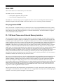
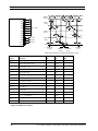
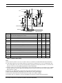
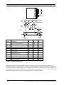
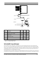
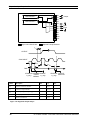
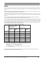
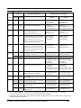
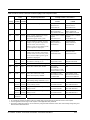
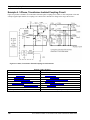
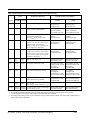
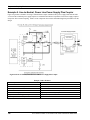
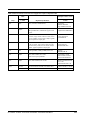
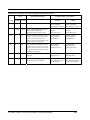
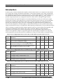
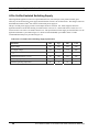
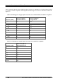
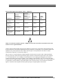
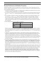
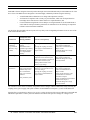
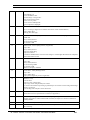
Table 2.7 External Memory Interface Pins
Direction
Function
Pin
Designation
A0 - A15
Output
Address Pins
D0 - D7
Input/Output
Data Pins
E
Output
Enable Clock
R/W
output
Read/Write Select Low
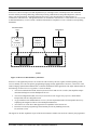
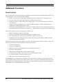
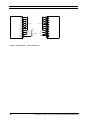
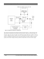
The PL Smart Transceiver can be interfaced to another MPU through the 12 I/O pins using a serial or parallel
connection, or through a dual-ported RAM device such as the Cypress CY7C144, CY7C138, or CY7C1342. There are
pre-defined serial and parallel I/O models for this purpose which are easily implemented. Use the Neuron C
programming language, ShortStack firmware, or MIP firmware to simplify the interface. For more details of dual-ported
RAM interfacing, see Appendix B of the LONWORKS Microprocessor Interface Program User’s Guide (Echelon 0780017-01).
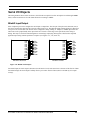
Input/Output
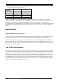
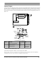
Twelve Bidirectional I/O Pins
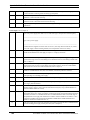
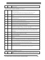
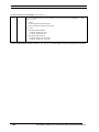
These pins are usable in several different configurations to provide flexible interfacing to external hardware and access
to the internal timer/counters. The logic level of the output pins can be read back by the application processor.
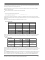
Pins IO4 – IO7 and IO11 have programmable pull-up current sources. They are enabled or disabled with a compiler
directive (see the Neuron C Reference Guide). Pins IO0 – IO3 have high current sink capability (20 mA @ 0.8 V). The
others have sink capability of 1.4 mA @ 0.5 V. All pins (IO0 – IO11) have TTL level inputs with hysteresis. Pins IO0 –
IO7 also have low level detect latches.
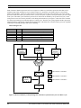
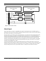
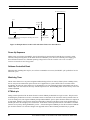
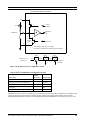
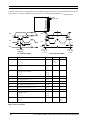
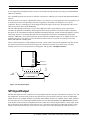
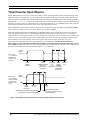
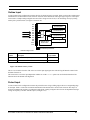
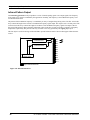
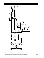
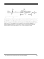
Two 16-Bit Timer/Counters
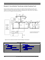
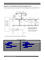
The timer/counters are implemented as a load register writable by the processor, a 16-bit counter, and a latch readable
by the processor. The 16-bit registers are accessed 1 byte at a time. The PL Smart Transceivers have one timer/counter
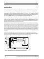
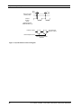
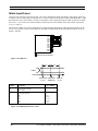
whose input is selectable among pins IO4 – IO7, and whose output is pin IO0, and a second timer/counter with input
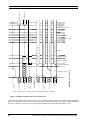
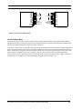
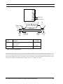
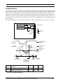
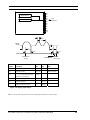
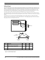
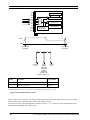
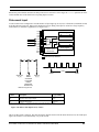
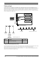
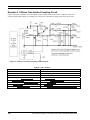
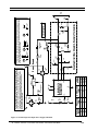
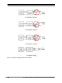
from pin IO4 and output to pin IO1 (Figure 2.7). No I/O pins are dedicated to timer/counter functions. If, for example,
Timer/Counter 1 is used for input signals only, then IO0 is available for other input or output functions. Timer/counter
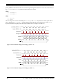
clock and enable inputs can be from external pins, or from scaled clocks derived from the system clock; the clock rates
of the two timer/counters are independent of each other. External clock actions occur optionally on the rising edge, the
falling edge, or both rising and falling edges of the input.
20
PL 3120/PL 3150/PL 3170 Power Line Smart Transceiver Data Book