1
4 Boiler installation sequence
4.15 Controls
4.15.1
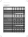
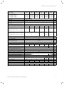
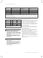
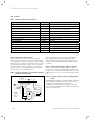
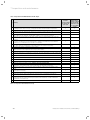
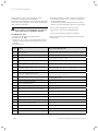
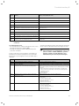
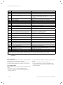
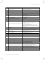
Vaillant controls and accessories
Controller
Item no.
Connection
VRC 400 (1-circuit controller, weather-controlled)
00 2001 0843
Installation in electronics box (plug-and-play)
VRT 360 (room temperature controller)
00 2001 0842
Wall-mounted, 2-wire bus
Available from 10-01-2006
VRT 360f (room temperature controller)
00 2001 8258
Wireless controller, receiver wall-mounted
VRT 230 (room temperature controller)
00 2001 0841
Wall-mounted, 3-wire connection to terminals 3-4-5
timeSWITCH 140 (timer)
306 760
Installation in electronics box (plug-and-play)
timeSWITCH 130 (timer)
306 759
Installation in electronics box (plug-and-play)
VRT 30 (room thermostat)
300 637
Wall-mounted, 3-wire connection to terminals 3-4-5
VRT 50 (room thermostat)
00 2001 8265
Telecommunication
Item no.
Wall-mounted, 2-wire bus
Connection
vrnetDIALOG 830 (Int)
00 2000 3988
GSM/GPRS, installation in electronics box (plug-and-play)
vrnetDIALOG 860/2 (Int)
00 2000 3984
Wall-mounted, GSM/GPRS, up to 16 appliances
Accessories
Item no.
Connection
VR 65 control centre for UK cylinder installation (eBUS)
307 215
System solution for UK cylinder connection
vrDIALOG 810/2
00 2002 3370
Diagnostic software
Table 4.1 Vaillant controls and accessories
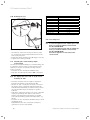
4.15.2 External electrical controls
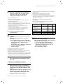
The boiler terminals 3, 4 and 5 are for connecting
external electrical controls such as a time switch and/or
room thermostat. Terminals 3 and 4 are linked together
when the boiler is supplied. If external controls are used,
this link must be removed, and the controls connected
across terminals 3 and 4. Terminal 5 is an additional
neutral connection for external neutrals such as from
the anticipator of a room thermostat.
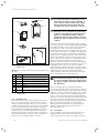
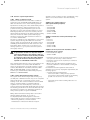
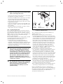
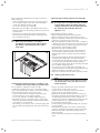
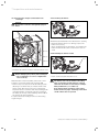
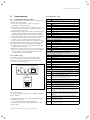
4.15.3 Connection details for external time switches
and boiler terminal strip
20 VDC
7
8
9
(DO NOT USE 7, 8, 9 IN UK!)
L N
5
3 4
N
L
SWITCH
CONTACTS
3 A FUSE
ROOM
THERMOSTAT
If a room thermostat is to be connected in addition to a
time switch the wire between the time switch “ON”
terminal and boiler terminal 4 should be broken by the
contacts of the room thermostat (see schematic layout,
Fig. 4.18).
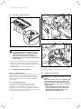
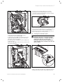
4.15.4 Vaillant optional plug in timer accessories
Refer to the instructions supplied with the optional
accessories for connection details. Upon completion of
all electrical connections refit the terminal box cover by
pushing into place. The cover is secured by two locking
clips.
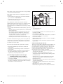
4.15.5 Connection details using the VR 65 Control
Center
The VR 65 Control Center is an eBUS system component.
In a storage unit installation, it is responsible for the
communication between the storage unit, the
ecoTEC plus system boilers and external 2- or 3-wayvalves. Connect the VR 65 Controll Center as described
in the enclosed manual.
MAINS
SUPPLY
230 V
50 Hz
L
N
CLOCK
N
Fig. 4.18 Connection details for time switches
30
Instructions for installation and servicing ecoTEC 839592_12