1
Troubleshooting 9
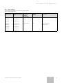
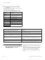
Display
Meaning
d.00
d.02
Test operation on 1st burner stage for gas setting (only for 0 = Normal operation (both stages)
2-stage boilers)
1 = After starting switching back to the 1st stage
2 = Full output (2nd stage)
Heating pump overrun Starts after ending of heat demand 5 .. 60 min,
“-” for continuous
Burner locking time Starts after ending of heat demand
2 .. 60 min
d.04
Measured value of storage temperature
d.05
Flow temperature target value
in °C
d.07
Display of storage tank target temperature
Adjustable from 40 - 70 °C (15 °C -signifies frost protection)
d.08
Room thermostat at terminal 3-4
d.09
d.10
Supply target temperature from external controller to
terminal 7-8-9
Heating pump
1 = closed (heat mode)
0 = opened (no heat mode)
in °C (continuous control)
d.11
Heating pump (via accessories)
1 = on, 0 = off
d.12
Cylinder charging pump
1 = on, 0 = off
d.13
Circulation pump
1 = on, 0 = off
d.01
Display value/adjustable value
in °C
1 = on, 0 = off
d.16
Changeover external pump/solar pump
2 = Normal mode
d.22
Demand for storage tank charging via contact C1/C2
1 = yes, 0 = no
d.23
Operating mode Summer /winter function
1 = Heating on, 0 = Heating off
d.25
Release for storage tank charging from external controller
1 = yes, 0 = no
d.30
Heat demand from electronics
1 = yes, 0 = no
d.40
Feed temperature actual value
in °C
d.46
External temperature correction value
Setting range -10 ... +10 (factory setting: 0)
d.47
External temperature actual value
in °C
d.48
Exhaust gas sensor actual temperature value
in °C
d.50
Switch-off hysteresis of feed controller
Setting range 0 ... +10 (factory setting: 6)
d.51
Switch-on hysteresis of feed controller
Setting range 0 ... +10 (factory setting: -2)
d.60
Number of temperature limiting shutdowns
Amount
d.61
Amount
d.68
Number of fuel automatic system faults
= Number of successful ignitions in the last attempt
Number of unsuccessful ignitions in the first attempt
d.69
Number of unsuccessful ignitions in the second attempt
Amount
d.71
Maximum heating feed temperature
Setting range 50 °C ... 87 °C (factory setting: 82 °C)
d.72
Pump overrun time storage tank charging
Setting range 0, 10, 20, ... 600 s (factory setting: 180 s)
d.75
Setting range 75 °C ... 90 °C (factory setting: 85 °C)
d.76
Maximum charging time for a storage without own
controller
Appliance variants
d.78
Limiting of storage tank charging temperature
Setting range 75 °C ... 90 °C (factory setting: 85 °C)
d.79
1 = active, 0 = off
d.80
Legionella protection (display only with controller
connected)
Number of heating operating hours 1)
d.81
Number of storage tank operating hours 1)
u xx 1.000 + xxx (in h)
d.82
Number of burner starts heating 1)
Amount
15
u xx 1.000 + xxx (in h)
u xx 100.000 + xxx 100 (number)
1)
d.83
Number of burner starts hot water operation
d.84
Number of hours until the next maintenance
Setting range 0 ... 300 and “-” (factory setting: “-”)
d.85
Minimum feed target temperature
Setting range 0 °C ... 60 °C
d.90
Digital controller
1 = detected, 0 = not detected
d.91
Status DCF
0 = no reception, 1 = reception, 2 = synchronised, 3 = valid
u xx 100.000 + xxx 100 (number)
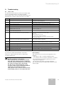
Table 9.3 Diagnosis codes
1) The first two displayed numbers must be multiplied by a factor of
1000 (or 100,000). By pushing the “i” button again the hours (or
the number x 100) are displayed in three figures.
Installation and maintenance manual atmoCRAFT
GB
39