1
Stage Piano
User’s Guide
©1999 All rights reserved. Kurzweil is a product line of Young Chang Co.; V. A. S. T. is a registered
trademark, and Kurzweil, SP76, SP88, and K2600 are trademarks of Young Chang Co. All other
products and brand names are trademarks or registered trademarks of their respective companies.
Product features and speciÞcations are subject to change without notice.
Part Number: 910329 Rev. A
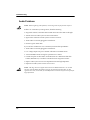
The lightning flash with the arrowhead symbol,
within an equilateral triangle, is intended to alert
the user to the presence of uninsulated
"dangerous voltage" within the product's
enclosure that may be of sufficient magnitude
to constitute a risk of electric shock to persons.
CAUTION
RISK OF ELECTRIC SHOCK
DO NOT OPEN
The exclamation point within an equilateral
triangle is intended to alert the user to the
presence of important operating and
maintenance (servicing) instructions in the
literature accompanying the product.
CAUTION: TO REDUCE THE RISK OF ELECTRIC SHOCK,
DO NOT REMOVE THE COVER
NO USER SERVICEABLE PARTS INSIDE
REFER SERVICING TO QUALIFIED SERVICE PERSONNEL
IMPORTANT SAFETY & INSTALLATION INSTRUCTIONS
INSTRUCTIONS PERTAINING TO THE RISK OF FIRE, ELECTRIC SHOCK, OR INJURY TO PERSONS
WARNING: When using electric products, basic precautions should
always be followed, including the following:
1. Read all of the Safety and Installation Instructions and
Explanation of Graphic Symbols before using the product.
2. This product must be grounded. If it should malfunction or
break down, grounding provides a path of least resistance for
electric current to reduce the risk of electric shock. This
product is equipped with a power supply cord having an
equipment-grounding conductor and a grounding plug. The
plug must be plugged into an appropriate outlet which is
properly installed and grounded in accordance with all local
codes and ordinances.
DANGER: Improper connection of the equipment-grounding
conductor can result in a risk of electric shock. Do not modify
the plug provided with the product - if it will not fit the outlet,
have a proper outlet installed by a qualified electrician. Do not
use an adapter which defeats the function of the equipmentgrounding conductor. If you are in doubt as to whether the
product is properly grounded, check with a qualified
serviceman or electrician.
3. WARNING: This product is equipped with an AC input voltage
selector. The voltage selector has been factory set for the
mains supply voltage in the country where this unit was sold.
Changing the voltage selector may require the use of a
different power supply cord or attachment plug, or both. To
reduce the risk of fire or electric shock, refer servicing to
qualified maintenance personnel.
4. Do not use this product near water - for example, near a
bathtub, washbowl, kitchen sink, in a wet basement, or near a
swimming pool, or the like.
5. This product should only be used with a stand or cart that is
recommended by the manufacturer.
6. This product, either alone or in combination with an amplifier
and speakers or headphones, may be capable of producing
sound levels that could cause permanent hearing loss. Do not
operate for a long period of time at a high volume level or at a
level that is uncomfortable. If you experience any hearing loss
or ringing in the ears, you should consult an audiologist.
7. The product should be located so that its location or position
8.
9.
10.
11.
12.
13.
14.
15.
does not interfere with its proper ventilation.
The product should be located away from heat sources such
as radiators, heat registers, or other products that produce
heat.
The product should be connected to a power supply only of
the type described in the operating instructions or as marked
on the product.
This product may be equipped with a polarized line plug (one
blade wider than the other). This is a safety feature. If you are
unable to insert the plug into the outlet, contact an electrician
to replace your obsolete outlet. Do not defeat the safety
purpose of the plug.
The power supply cord of the product should be unplugged
from the outlet when left unused for a long period of time.
When unplugging the power supply cord, do not pull on the
cord, but grasp it by the plug.
Care should be taken so that objects do not fall and liquids are
not spilled into the enclosure through openings.
The product should be serviced by qualified service personnel
when:
A. The power supply cord or the plug has been damaged;
B. Objects have fallen, or liquid has been spilled into the
product;
C. The product has been exposed to rain;
D. The product does not appear to be operating normally or
exhibits a marked change in performance;
E. The product has been dropped, or the enclosure
damaged.
Do not attempt to service the product beyond that described
in the user maintenance instructions. All other servicing
should be referred to qualified service personnel.
WARNING: Do not place objects on the product’s power
supply cord, or place the product in a position where anyone
could trip over, walk on, or roll anything over cords of any type.
Do not allow the product to rest on or be installed over cords
of any type. Improper installations of this type create the
possibility of a fire hazard and/or personal injury.
RADIO AND TELEVISION INTERFERENCE
WARNING: Changes or modifications to this instrument not
expressly approved by Young Chang could void your authority to
operate the instrument.
IMPORTANT: When connecting this product to accessories and/or
other equipment use only high quality shielded cables.
NOTE: This instrument has been tested and found to comply with
the limits for a Class B digital device, pursuant to Part 15 of the FCC
Rules. These limits are designed to provide reasonable protection
against harmful interference in a residential installation. This
instrument generates, uses, and can radiate radio frequency energy
and, if not installed and used in accordance with the instructions,
may cause harmful interference to radio communications. However,
there is no guarantee that interference will not occur in a particular
installation. If this instrument does cause harmful interference to
radio or television reception, which can be determined by turning the
instrument off and on, the user is encouraged to try to correct the
interference by one or more of the following measures:
• Reorient or relocate the receiving antenna.
• Increase the separation between the instrument and the receiver.
• Connect the instrument into an outlet on a circuit other than the
one to which the receiver is connected.
• If necessary consult your dealer or an experienced radio/
television technician for additional suggestions.
NOTICE
This apparatus does not exceed the Class B limits for radio noise
emissions from digital apparatus set out in the Radio Interference
Regulations of the Canadian Department of Communications.
AVIS
Le present appareil numerique n’emet pas de bruits
radioelectriques depassant les limites applicables aux appareils
numeriques de la class B prescrites dans le Reglement sur le
brouillage radioelectrique edicte par le ministere des
Communications du Canada.
SAVE THESE INSTRUCTIONS
ii
Young Chang Distributors
Contact the nearest Young Chang ofÞce listed below to locate your local Young Chang/
Kurzweil representative.
Young Chang America, Inc.
P.O. Box 99995
Lakewood, WA 98499-0995
Tel: (253) 589-3200
Fax: (253) 984-0245
Young Chang Co.
178-55 Gajwa-Dong
Seo-Ku, Inchon, Korea 404-714
Tel: 011-82-32-570-1380
Fax: 011-82-32-570-1218
Young Chang Akki Europe GmbH
Industriering 45
D-41751 Viersen
Germany
Tel: 011-49-2162-4491
Fax: 011-49-2162-41744
Young Chang Canada Corp.
250 Shields Court, Unit #11
Markham, Ontario L3R 9W7
Tel: (905) 948-8052
Fax: (905) 948-8172
iii
Contents
Young Chang Distributors ....................................................................... iii
Chapter 1
Introducing the Stage Piano
Welcome! .................................................................................................. 1-1
Stage Piano Overview ............................................................................ 1-1
Sound, Internal Voices Setup, MIDI Setup ................................... 1-1
The Keyboard........................................................................................... 1-2
The Front Panel........................................................................................ 1-2
The Ribbon Controllers .......................................................................... 1-2
Other Controllers..................................................................................... 1-2
Connectors................................................................................................ 1-3
Modes........................................................................................................ 1-3
How to Use This Book ............................................................................ 1-3
Chapter 2
Getting Started
Unpacking the Instrument..................................................................... 2-1
Quick Start................................................................................................ 2-1
Playing the Demo .................................................................................... 2-2
Placement and Support .......................................................................... 2-2
The Rear Panel ......................................................................................... 2-2
Power Switch .................................................................................... 2-3
Power Jack......................................................................................... 2-3
Audio Jacks ....................................................................................... 2-3
Phones Jack ....................................................................................... 2-3
Switch Pedal Jack ............................................................................. 2-3
Control Pedal Jack............................................................................ 2-3
MIDI Ports......................................................................................... 2-4
Connecting Switch Pedals .............................................................. 2-4
A Special Note About Switch Pedals............................................. 2-4
Connecting a Control Pedal............................................................ 2-4
Connecting to Your Audio System ....................................................... 2-5
Changing to Mono Output ............................................................. 2-5
Connecting Headphones........................................................................ 2-6
Connecting MIDI..................................................................................... 2-6
Basic MIDI Hookup ......................................................................... 2-6
Connecting More Sound Modules................................................. 2-7
Connecting to a Computer Sequencer .......................................... 2-8
Full System...................................................................................... 2-10
The Front Panel.......................................................................................2-11
v
The Kurzweil Stage Piano User’s Guide
Sound and Setup Select Buttons ...................................................2-11
The Numeric Display .....................................................................2-11
Mode LEDs ..................................................................................... 2-12
Parameter Editing Buttons............................................................ 2-12
The Parameter Display.................................................................. 2-12
The Info Strip .................................................................................. 2-12
Button Combinations..................................................................... 2-13
Direct Select ............................................................................. 2-13
Panic.......................................................................................... 2-13
Demo Song............................................................................... 2-13
What Mode Am I In? ............................................................................ 2-14
Chapter 3
Internal Voices Mode
Selecting Internal Voices Mode ............................................................. 3-1
Selecting Sounds .............................................................................. 3-1
Modifying Effects............................................................................. 3-2
Saving a SoundÕs Effects Settings.......................................................... 3-3
Modifying The MIDI Transmit Channel .............................................. 3-3
Sending a MIDI Program Change......................................................... 3-4
Modifying Other Internal Voice Parameters ....................................... 3-4
MIDI Program .................................................................................. 3-4
MIDI Bank Sel Lo ............................................................................. 3-4
MIDI Channel ................................................................................... 3-5
Destination ........................................................................................ 3-5
Internal Effect.................................................................................... 3-5
Transpose........................................................................................... 3-5
Velocity Curve .................................................................................. 3-5
Reverb Wet/Dry, Chorus Wet/Dry ............................................... 3-5
A Ribbon............................................................................................ 3-5
Hold or Center.................................................................................. 3-5
B Ribbon Up, B Ribbon Down........................................................ 3-5
Hold or Zero ..................................................................................... 3-6
Control Slider, Control Pedal ......................................................... 3-6
Switch Pedal R, Switch Pedal L...................................................... 3-6
Editing Basics........................................................................................... 3-6
Edit vs. Play Mode ........................................................................... 3-7
Selecting a Parameter ...................................................................... 3-7
Increment/Decrement Editing....................................................... 3-7
Direct Numerical Editing................................................................ 3-8
Cancelling Edits................................................................................ 3-8
Saving The Edited Parameters ....................................................... 3-8
vi
The Kurzweil Stage Piano User’s Guide
Chapter 4
MIDI Setups Mode
Selecting Setups ....................................................................................... 4-1
Zones ......................................................................................................... 4-2
Editing MIDI Setups ............................................................................... 4-3
Saving a ModiÞed MIDI Setup.............................................................. 4-3
Sending a MIDI Program Change ........................................................ 4-4
Parameter Summary ............................................................................... 4-4
Internal Sound .................................................................................. 4-4
MIDI Program .................................................................................. 4-4
MIDI Bank Sel Lo, MIDI Bank Sel Hi............................................ 4-4
MIDI Channel ................................................................................... 4-4
Destination ........................................................................................ 4-5
Internal Effect.................................................................................... 4-5
Key Range Lo, Key Range Hi ......................................................... 4-5
Transpose........................................................................................... 4-5
Velocity Curve .................................................................................. 4-6
Reverb Wet/Dry, Chorus Wet/Dry ............................................... 4-6
A Ribbon............................................................................................ 4-6
Hold or Center.................................................................................. 4-6
B Ribbon Up, B Ribbon Down........................................................ 4-7
Hold or Zero ..................................................................................... 4-7
Control Slider, Control Pedal ......................................................... 4-7
Switch Pedal R, Switch Pedal L...................................................... 4-7
MIDI Controller Destinations................................................................ 4-7
Continuous Controller Destinations .................................................... 4-8
Switch Controller Destinations ............................................................. 4-9
More on Keyboard Splits.......................................................................4-11
Changing Setups: Special Considerations .........................................4-11
Chapter 5
Global Parameters
Access to the Global Parameters ........................................................... 5-1
What the Global Parameters Do .................................................... 5-1
Local............................................................................................ 5-1
Stereo .......................................................................................... 5-1
Touch .......................................................................................... 5-2
Effect ........................................................................................... 5-3
MIDI In ....................................................................................... 5-3
Set Change Channel ................................................................. 5-3
Tune ............................................................................................ 5-3
Saving Global Parameters............................................................... 5-4
vii
The Kurzweil Stage Piano User’s Guide
Chapter 6
Advanced Applications
External Sound Modules........................................................................ 6-1
Example: The Kurzweil MicroPiano ............................................ 6-1
Example: The Kurzweil K2600R ................................................... 6-2
Computer Sequencers............................................................................. 6-2
MIDI Hookup ................................................................................... 6-3
Local Control Off and Patch Thru On........................................... 6-3
Basic Sequencer Operations............................................................ 6-3
Saving Setup Memory ..................................................................... 6-4
Reloading Setup Memory ............................................................... 6-5
External MIDI Processors....................................................................... 6-5
Receive Program Change................................................................ 6-6
Example: The Kurzweil ExpressionMate .................................... 6-6
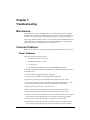
Chapter 7
Troubleshooting
Maintenance............................................................................................. 7-1
Common Problems ................................................................................. 7-1
Power Problems ............................................................................... 7-1
Audio Problems................................................................................ 7-2
MIDI Problems ................................................................................. 7-3
Switch Pedal Problems .................................................................... 7-3
Control Pedal Problems .................................................................. 7-4
Use the Right Impedance, Taper, and Range ........................ 7-5
If None of the AboveÉ ................................................................... 7-5
Service Centers ........................................................................................ 7-5
Restoring Factory Defaults .................................................................... 7-6
Diagnostics ............................................................................................... 7-6
Starting Diagnostics......................................................................... 7-6
Main Diagnostic Menu.................................................................... 7-6
Player Control Diagnostic........................................................ 7-7
Testing the Keyboard ........................................................ 7-7
Testing the Ribbons ........................................................... 7-7
Testing the Switch Pedals ................................................. 7-7
Testing the Control Pedal ................................................. 7-7
Testing the Buttons and LEDs.......................................... 7-8
CPU Diagnostics ....................................................................... 7-8
ROM Test (rom).............................................................. 7-8
EEPROM Test (eer) ...................................................... 7-8
MIDI Test (mid).............................................................. 7-8
Timers Test (tim) ........................................................... 7-8
Burnin Test (bur) .......................................................... 7-9
Initialize EEPROM (ini).............................................. 7-9
viii
The Kurzweil Stage Piano User’s Guide
Sound Board Diagnostics......................................................... 7-9
Interface Test (inf)........................................................ 7-9
ROM Test (rom).............................................................. 7-9
RAM Test (ram).............................................................. 7-9
Timers Test (tim) ........................................................... 7-9
Sound ROM Test (snr) ................................................. 7-9
Sound Chip Test (snc) .................................................. 7-9
Delay RAM Test (drm) ................................................ 7-10
Sine Wave Test (sin)................................................... 7-10
Burnin Test (bur)......................................................... 7-10
Jumper Settings Display ........................................................ 7-10
Exiting Diagnostics ................................................................. 7-10
Chapter 8
Reference
Display Characters .................................................................................. 8-1
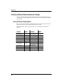
Factory Default Internal Voices Setup ................................................. 8-2
Internal Voices Parameters ............................................................. 8-2
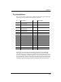
The Internal Voices .......................................................................... 8-3
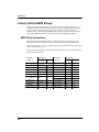
Factory Default MIDI Setups................................................................. 8-4
MIDI Setup Parameters................................................................... 8-4
Factory Default Global Parameters ...................................................... 8-5
Stage Piano Effects .................................................................................. 8-5
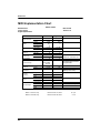
MIDI Implementation Chart.................................................................. 8-6
Default MIDI Controller Assignments................................................. 8-7
Specifications ........................................................................................... 8-8
Controllers......................................................................................... 8-8
Standard ..................................................................................... 8-8
Optional...................................................................................... 8-8
User Interface.................................................................................... 8-8
Display........................................................................................ 8-8
Buttons........................................................................................ 8-8
Audio ................................................................................................. 8-8
Output Connections ................................................................. 8-8
Impedance.................................................................................. 8-8
Electrical Requirements................................................................... 8-9
Environment ..................................................................................... 8-9
Operating ................................................................................... 8-9
Storage ........................................................................................ 8-9
Physical Dimensions........................................................................ 8-9
SP76............................................................................................. 8-9
SP88............................................................................................. 8-9
Index
ix
Chapter 1
Introducing the Stage Piano
Welcome!
Congratulations, and thank you for purchasing a Kurzweil / Young Chang Stage
Piano. YouÕve got your hands on an excellent-sounding and ßexibleÑyet
economicalÑperformance instrument and MIDI controller.
This manual will get you started with your new instrument. YouÕll deÞnitely want to
keep the manual handy as you become an advanced user, also.
Stage Piano Overview
The Stage Piano is a great live performance instrument. It has many excellent
keyboard sounds (voices), including the famous Kurzweil Grand Piano, already
programmed and ready to go. It is also a ßexible MIDI controller ideally suited for
controlling additional sound modules and as input to a sequencer.
Sound, Internal Voices Setup, MIDI Setup
WeÕll use these three terms throughout this manual. TheyÕre the components of the
Stage PianoÕs performance features.
Sounds are the 32 internal voices of the Stage Piano: pianos, organs, strings.
The Internal Voices Setup is the basic conÞguration of your Stage Piano for standalone
performance (no external sound modules or sequencers). The Internal Voices Setup
speciÞes which sound youÕll hear, and with which audio effect (if any) applied to it. It
speciÞes several other performance features as well:
¥ What the physical controllers (like ribbons and pedals) do
¥ Transposition
¥ MIDI channel
¥ MIDI Program Change commands
ThereÕs one Internal Voices Setup, and itÕs programmableÑthat is, you can change
these speciÞcations, and save those changes to the Stage PianoÕs memory.
There are 32 MIDI Setups, each of which controls the same features as the Internal
Voices Setup. When youÕre using a MIDI Setup, the Stage PianoÕs keyboard has two
zones, which can be anywhere on the keyboard (even overlapping). This enables you
to play the Stage Piano and control two external MIDI instruments at the same time.
You can edit and save each MIDI Setup.
Introducing the Stage Piano
The Keyboard
The Keyboard
Depending on model, the keyboard has 76 keys (E1ÐG7) or a full 88 keys (A0ÐC8).
These are full-sized, weighted keys, the equal of keyboards found on more expensive
synthesizers and controllers. The keyboard is velocity-sensitive, meaning the harder
(faster) you press a key, the louder the voice (except for organ voices which,
realistically, are not velocity-sensitive).
As a MIDI controller, the keyboard is also release-velocity-sensitive, meaning that MIDI
signals expressing how rapidly a key is released get sent to external equipment.
The Front Panel
The front panel has a 3-digit numeric display, 10 mode and editing status LEDS, 16
sound/setup select buttons with dual-color LEDs, and 4 editing buttons. The sound/
setup select buttons make random selection of 32 different sounds or MIDI Setups
quick and easy while the display and LEDs shows the unitÕs present status at a glance.
The Ribbon Controllers
The Stage Piano also has 3 ribbon controllers, which take the place of conventional
wheels and offer signiÞcant advantages. The A ribbon (the one on the left) typically
performs a pitch bending function with the upper half bending pitch upwards and the
lower half bending pitch downwards. Pressing the center bar restores pitch to normal.
The B ribbon is actually split into upper and lower sections. Each section can control a
different characteristic of the sound simultaneously. This is like having two
conventional modulation wheels. Pressing the center bar removes both modulations.
NOTE: The sounds of the Stage Piano do not respond to pitch bending, or to the lower section
of the B ribbon. External MIDI devices may respond to the signals sent by these controllers.
An advantage of ribbons over conventional wheels is that their mode is programmable.
A conventional pitch wheel is spring-loaded so that it always returns to its center
position (no pitch change) when released. Conventional modulation wheels usually
do not spring back, and remain where they were when released. Likewise these are the
default modes of the A and B ribbons respectively, but each can also be set to operate
in the opposite mode. See Hold or Center and Hold or Zero on page 3-6 for details.
Other Controllers
The Volume/Controller slider is actually a general purpose control. Although its
default setting is to control volume (MIDI Volume), it can be set to control any aspect
of the sound. See Control Slider, Control Pedal on page 3-6 for more information.
One Control Pedal can be plugged into the rear panel to permit foot control over the
sound. The foot controller can be set to control volume, modulation, or other sound
parameters. See Control Slider, Control Pedal on page 3-6 for details.
A single or dual switch pedal (piano pedal) can also be plugged into the rear panel. By
default, a single pedal or the right half of a dual pedal will perform a sustain (or
damper) function while the left half of a dual pedal will perform sostenuto. See
Connecting Switch Pedals on page 2-4 and A Special Note About Switch Pedals on page 2-4
for more.
1-2
Introducing the Stage Piano
Connectors
Connectors
The rear panel has a total of 8 connectors:
¥ Left and Right audio jacks accept standard 1/4-inch mono plugs connected to your
stereo audio system. (See Changing to Mono Output on page 2-5 for how to obtain a
mono output.)
¥ Headphone jack accepts a standard 1/4-inch stereo plug.
¥ MIDI In and Out jacks for connecting to external sound modules or a computer.
¥ Control pedal jack for connecting to a continuous-control pedal.
¥ Switch pedals jack for connecting to a single or dual piano-pedal unit.
¥ DC power jack for receiving 12V DC power from the supplied power adapter.
Connecting to and using all of these connectors is described thoroughly in the
following sections.
Modes
The Stage Piano operates in one of two fundamental modes.
When in Internal Voices mode, the Stage Piano is an easy to understand and operate,
stand-alone performance instrument. To change sounds, just press one of the 16 sound
select buttons. The entire keyboard will always play the sound named on the sound
select button. See Chapter 3 for more on Internal Voices mode.
When in MIDI Setups mode, the Stage Piano becomes a sophisticated MIDI controller
with a built-in sound module. The keyboard can be split into 2 sections or zones, each
going to a different MIDI channel. Up to 32 different MIDI setups can be deÞned and
stored in the built-in nonvolatile memory. You can quickly select these setups with the
16 sound/setup select buttons. In MIDI Setups mode, any sound (or none at all) can be
associated with each setup. See Chapter 4 for details about MIDI Setups mode.
How to Use This Book
This Stage Piano UserÕs Guide is designed to help you get up and running quickly. If
you know electronic instruments and MIDI already and you know pretty much what
you want to do with your Stage Piano, at least read Quick Start on page 2-1. If you
need some more help on using the Stage PianoÕs many features, you should also read
all of Chapters 3 and 4. Chapters 5 and 6 give more information on global functions
and describe some typical applications. The remaining chapters provide
troubleshooting and reference material that can be referred to when needed. Finally,
donÕt underestimate the index. WeÕve tried to think of every word and topic you may
need quick access toÑitÕs the next best thing to a search engine!
Also, donÕt forget to check our web site for any late-breaking information on the Stage
Piano and other Kurzweil products:
http://www.youngchang.com/kurzweil
Above all, have fun, and make lots of great music with your Stage Piano!
1-3
Chapter 2
Getting Started
This chapter will help you hook up your Stage Piano and learn its basic functions.
Unpacking the Instrument
The box that your Stage Piano ships in contains the following:
¥ The Stage Piano
¥ AC Adapter (12V DC, 0.5A)
¥ Single switch pedal
¥ Four adhesive-backed rubber feet
¥ This manual
¥ Warranty card
Be sure to keep the box and packing materials, at least during the warranty period, in
case you need to ship the unit for any reason.
Quick Start
We recommend that you read through this whole chapter at some point. However, if
you want to start exploring your new instrument right away, follow these steps:
1.
Carefully remove all the contents of the box.
2.
Set the Stage Piano on a keyboard stand or table. For optimum stability,
particularly of the 88-key model, make sure the ends are supported, not just the
middle.
3.
Turn the power switch (at the rear of the unit) off then plug the power adapter
into the unit and into the wall. If youÕre not in the USA, check that the linevoltage rating of the adapter matches line voltage in your area.
4.
Plug a pair of headphones into the Phones jack on the back of the unitÑor
connect the Left and Right audio outputs to your audio system or mixer. The
outputs are unbalanced line-level (approximately 1V), so use the line or aux
inputs to your audio system.
5.
Plug the included switch pedal into the rear panel jack marked Switch Pedals.
6.
Turn the power switch to the On position. The display and all of the LEDs
should light brießy, then the Internal Voices and Grand Piano LEDs should
light.
7.
Play away. Use the Volume/Controller slider or your audio systemÕs volume
control to vary the volume. Press a sound/setup select button once to hear the
red sound; twice to hear the green. See Sound and Setup Select
Buttons on page 2-11 if you donÕt understand about red and green sounds.
Read on for more details about each of these steps.
Getting Started
Playing the Demo
Playing the Demo
To play the demonstration song, press the left-most two buttons (Internal/Setup and
MIDI Prog Change) at the same time. YouÕll hear a short demonstration of the sounds
and effects. The unit must be in Play mode (all LEDs to the left of the display off) for
this to work. The demo can be stopped before it is complete by pressing any button.
NOTE: MIDI signals from the demo song will not be sent.
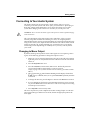
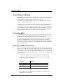
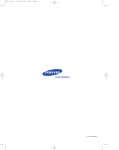
Placement and Support
The Stage Piano is designed to be used on a keyboard stand or on a ßat table. For
tables, we recommend attaching the included rubber feet to the bottom to avoid
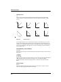
scratching the table when moving the unit. Refer to Figure 2-1 for the best places to
attach the feet.
Figure 2-1
Placement of Rubber Feet
The Stage Piano will feel most stable when supported along its entire length,
especially at both ends. Place it on a hard ßat surface to keep it from rocking. If
desired, it can be tilted without affecting the feel of the keyboard.
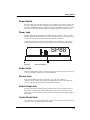
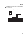
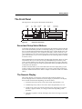
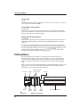
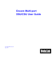
The Rear Panel
Here are descriptions of the rear-panel connectors, as illustrated in Figure 2-2.
Figure 2-2
2-2
Stage Piano Rear Panel
Getting Started
The Rear Panel
Power Switch
Press the white dot to turn the Stage Piano on or the blank area to turn it off. If it will
be off for a long period of time, unplug the power adapter from the wall. The Stage
PianoÕs hi-tech EEPROM memory is like a computerÕs hard drive and needs no power
or battery to retain information. So there is no advantage in leaving the power on.
Power Jack
Plug the cord from the included power adapter into this jack. Try to always use the
adapter supplied with the unit. However, if it should become lost or forgotten, refer to
SpeciÞcations on page 8-8 for information about possible substitutes.
To help prevent the power cord from being pulled out accidentally, a cord retainer is
mounted near the power jack. To use, just wrap a 3/4 loop around it as illustrated.
12VDC
Figure 2-3
0.5A
SP88
Power Cord Retainer
Audio Jacks
The left and right audio jacks are used to connect to your audio system. See Connecting
to Your Audio System on page 2-5 for connection details.
Phones Jack
Plug your headphones in here. YouÕll need a Ò1/4 -inch to-1/8-inchÓ (or
Òphone-to-miniÓ) adapter plug when using headphones that have a mini plug. See
Connecting Headphones on page 2-6 for additional information.
Switch Pedal Jack
Use this jack to plug in the single piano pedal that came with your Stage Piano. For
this pedal to work properly, it must be plugged in before power is turned on. See A
Special Note About Switch Pedals on page 2-4 for info about using aftermarket single or
dual pedals.
Control Pedal Jack
You can plug a control pedal in here but be careful, not every kind will work well. See
Connecting a Control Pedal on page 2-4 for details.
2-3
Getting Started
The Rear Panel
MIDI Ports
Use the MIDI Out port to connect to an external sound module like a Kurzweil
K2600R. Use the MIDI In port to connect to a computer for use in sequencer
applications. See page 2-6 through page 2-10 for more possibilities.
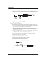
Connecting Switch Pedals
The included single switch pedal will, by default, act like a piano damper pedal and
will control sustain. Of course this can be changed by programming as described in
Chapters 3 and 4.
The jack will also accept a dual switch pedal having a single stereo plug which is
available separately (Kurzweil KFP-2M). The plug should be wired so that the left
pedal connects to the ring contact and the right pedal to the tip contact. ItÕs also
possible to use two single pedals. First buy a 1/4-inch stereo-to-dual-mono Y adapter.
This will have two mono 1/4-inch phone jacks and a stereo 1/4-inch plug.
Combinations of adapters can be used if that exact item is not available. Then plug the
pedal you wish to use for sustain into the left jack and your sostenuto pedal into the
right jack. Note that the ÒleftÓ pedal goes into the right jack and vice-versaÑone of
those confusing facts of life.
By default, the right pedal will control sustain as before and the left pedal will control
the sostenuto function. If youÕre not familiar with traditional piano technique, the
sostenuto (center) pedal on a grand piano allows one to hold chords in the bass while
continuing to play the melody without the latter notes sustaining. Any keys that are
down when you depress the pedal will sustain when you let go of the keys, but new
notes played afterward will not be sustained. Releasing the pedal puts things back to
normal. Of course it too can be programmed to do other functions as well.
A Special Note About Switch Pedals
If you choose to use aftermarket switch pedals, be aware that there are two kinds:
normally-open (like the included one) and normally-closed. Much Japanese
equipment uses the latter type. The Stage Piano will automatically adapt to either
typeÑif it is plugged in before the power is turned on; just donÕt step on it until the
power-up sequence is complete. If you Þnd that your pedal has become schizoid,
simply turn power off for a couple of seconds then back on and it will adapt.
CAUTION: Be sure not to step on the switch pedals when powering up your Stage Piano!
Connecting a Control Pedal
A control pedal can be very useful for controlling volume, vibrato, or other effect by
foot. The Kurzweil CC-1 control pedal will plug in directly and work perfectly but it is
also possible to use aftermarket ÒcontrolÓ pedals designed for synthesizers. A volume
pedal may or may not be satisfactory depending on how it is constructed. See Control
Pedal Problems on page 7-4 for pedal speciÞcations or if you are having trouble with
your control pedal.
2-4
Getting Started
Connecting to Your Audio System
Connecting to Your Audio System
The Audio Output jacks are professional 1/4-inch ÒphoneÓ jacks so if you are
connecting to an audio system with ÒRCAÓ jacks, you will need two Òphone plug-toRCA plugÓ adapter cables. Remember: always lower the volume of your audio
system when changing audio connectionsÑor better yet, turn the power off!
CAUTION: Be sure to lower the volume of your audio system or switch it off when changing
audio connections!
The source impedance of the audio output jacks is 1000 ohms, so they can drive
relatively long cables if needed. If connecting to a mixer, use a high-impedance,
unbalanced line input. If using a keyboard ampliÞer, its normal input should be Þne. If
using a home stereo system, inputs marked Aux should work well but Tuner and CD
inputs are generally OK. A guitar ampliÞer may work if it has Line or Aux inputs.
Avoid using a Guitar input though, it will likely be way too noisy and may distort
your sound.
Changing to Mono Output
By default, the Stage Piano produces stereo audio signals. In cases requiring a mono
signal, use the following procedure to change the outputs to mono:
1.
Make sure you are starting from Internal Voices Play mode. This is the default
right after power on. Only the Internal Voices LED and one of the sound LEDs
will be on.
2.
Press the Play/Edit button once.
3.
Press the Col Select (Column Select) button twice. Both of the parametercolumn LEDs should be off after doing so. (See The Parameter
Display on page 2-12 if you donÕt know what we mean by Òparameter-column
LEDs.Ó)
4.
The top parameter-row LED should be blinking and the display should show
ste (stereo) or mon (mono). If not, press Row Select repeatedly until this
is achieved.
5.
To change the selection, press the Up arrow button or the Down arrow button.
6.
If you would like for this change to be remembered next time power is turned
on, press the Store button twice. Otherwise it will revert to the previous setting
next time power is turned on.
7.
Press Play/Edit to return to Play mode.
The above sequence may seem complicated, but after reading Chapter 3 it will seem
quite simple and logical. When in mono mode, the left and right jacks produce the
same signal.
2-5
Getting Started
Connecting Headphones
Connecting Headphones
The Phones jack is designed to drive 100 ohm or greater headphones. Lower
impedance is safe too but the volume level can be reduced. You can also use a stereo Y
adapter and connect two headphones at the same time if they are 100 ohms or greater.
You can use headphones and an audio system at the same time; plugging in the
phones does not affect the line outputs at all. Note that if the instrument is switched to
mono mode as described above, the phones signal will also be mono, that is, the same
signal is heard from left and right.
The signal at the phones jack is just as high a quality as that at the line output jacks
described above. So if you prefer to use a single stereo cable to your audio system and
do not intend to use headphones, you can use the headphones output to drive your
audio system.
Connecting MIDI
The Stage Piano is a great live performance instrument all by itself but you can expand
its capabilities almost endlessly by using its MIDI (Musical Instrument Digital
Interface) connectors.
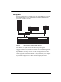
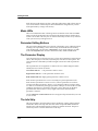
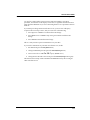
Basic MIDI Hookup
The simplest application of MIDI is to connect and control an external sound module
for more sounds, more polyphony, and more timbre control than the internal sound
module offers. The drawing below shows how simple this really is to do.
L
MIDI
In
R
MIDI
Out
L
Mode Select / Param Edit
Global
Grand Pno 1
Grand Pno 2
Intemal Sound
MIDI Program
Internal/Steup
Reverb Wet / Dry
Chorus Wet / Dry
Local
Stereo
A Ribbon
Hold or Center
Touch
MIDI Channel
Destination
B Ribbon Up
Hold or Zero
Effect
Intemal Effect
B Ribbon Down
Hold or Zero
MIDI In
MIDI Bank Sel Lo
MIDI Bank Sel Hi
Row Select
Internal Voices
1
Stage Pno 1
Stage Pno 2
2
1
Trem Dig EP
R
Zone
Key Range Lo
Key Range Hi
MIDI Prog Chg
Store
Play
Edit
Transpose
Velocity Curve
St Hard EP
6
Control Slider
Control Pedal
Set Chg Chan
Switch Pedal R
Switch Pedal L
Tune
Bright Pno
Sustain Pno
3
3
2
L
7
Piano & Str 1
Piano & Str 2
4
5
4
Digital EP
Dig EP & Str Pad
0 - Bank Select MSB
8
A
Tack Piano
Tite E Grand
5
7
6
Rock Org 1
Rock Org 2
11
10
Perc Org
Org & Piano
9
Bright E Grand
Warm E Grand
Ld/Dmp
9
8
Ballad Org 1
Ballad Org 2
0
12
Fast Str 1
Fast Str 2
+/-
Classic EP
Dig E Grand
No
Dyno EP
Hard Dyno EP
Yes
13
15
14
16
Touch Str
St Slo Strings
St Slo Str Pad
Slow Dig Pad
Cancel
17
19
18
20
21
23
25
27
22
24
26
28
SP88
MIXER
Built-In Effects
Award Winning Soungs
Flexible MIDI Controller
Enter
MIDI Setups
Destinations:
1 - Modulation Wheel
R
Sound / Setup Select
Parameter
Panic
Volume / Controller
29
31
30
32
Stage Piano
Effects:
5 - Portamento Time
6 - Data Entry MSB
10 - Pan
16 to 19 - Gennral Control 1 to 4
11 - Expression
20 to 31 - Undefined
12 - Effect Control 1
32 - Bank Select LSB
33 to 63 - LSB for 1 to 31
64 - Sustain Pedal
2 - Breath Controller
7 - Volume
3 - Undefined
4 - Foot Controller
8 - Balance
9 - Undefined
13 - Effect Control 2
14 to 15 - Undefined
65 - Portamento Switch
70 - Sound Variation
66 - Sostenuto Pedal
71 - Timbre Control
80 tp 83 - General Control 5 to 8
67 - Soft Peal
72 - Release Time
84 - Portamento Control
68 - Legato Switch
69 - Hold Pedal
73 - Attack Time
74 - Brightness
85 to 90 - Undefined
91 - Reverb Depth
75 to 79 - Sound Control 6 to 10
92 - Effects 2 Depth
97 - Data Decrement
93 - Chorus Depth
98 - Non-Reg Parm LSB
94 - Effects 4 Depth
99 - Non-Reg Parm MSB
128 - Send as Pitch Bend
2 - Bright Room & Chorus
7 - Large Hall & Chorus
95 - Effects 5 Depth
96 - Data Increment
100 - Registered Parm LSB
101 - Registered Parm MSB
129 - Send as Pressure
101 - Registered Parm MSB
4 - Bright Stage & Chorus
4 - Foot Controller
8 - Large Bright Hall & Chorus
9 - Deep Space
102 to 119 - Undefined
120 to 127 - Channel Mode Set
0 - None
1 - Room & Chorus
5 - Hall & Chorus
6 - Bright Hall & Chorus
B
Figure 2-4
MIDI Connections to External Module
The external sound module can be almost anything: a K2000R, K2500R, K2600R,
Kurzweil MicroPiano, and a world of other possibilities from alternative
manufacturers. It could be another keyboard synthesizer or large digital piano as well,
in fact nearly anything with a MIDI In connection.
With this simple setup you may be able to play up to 3 sounds at once; one from the
Stage PianoÕs sounds and 2 from the external module, if it is multitimbral. The external
module can make use of more of the Stage PianoÕs MIDI controls as well such as the
A Ribbon, lower B ribbon, and control pedal. MIDI Setups mode, which is covered in
Chapter 4, is used to control a setup like this.
2-6
Getting Started
Connecting MIDI
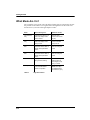
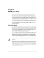
Connecting More Sound Modules
With MIDI, youÕre not limited to just one add-on sound module; you could connect 2,
3, or even more using the basic method illustrated below. Although your Stage Piano
will be able to play independent sounds on only 1 multitimbral or 2 monotimbral
modules at once, you can address up to 16 different external sounds using MIDI
Setups, all from your Stage PianoÕs front panel!
In
Thru
In
In
Thru
Thru
Module A
Module B
Module C
Out
Mode Select / Param Edit
Sound / Setup Select
Parameter
Global
Grand Pno 1
Panic
Grand Pno 2
Intemal Sound
MIDI Program
Volume / Controller
Internal/Steup
MIDI Bank Sel Lo
MIDI Bank Sel Hi
Row Select
Reverb Wet / Dry
Chorus Wet / Dry
Local
Stereo
A Ribbon
Hold or Center
Touch
B Ribbon Up
Hold or Zero
Effect
Internal Voices
1
Stage Pno 1
Stage Pno 2
2
1
Trem Dig EP
R
Zone
Play
Edit
Intemal Effect
B Ribbon Down
Hold or Zero
Key Range Lo
Key Range Hi
Control Slider
Control Pedal
Set Chg Chan
Switch Pedal R
Switch Pedal L
Tune
Transpose
Velocity Curve
St Hard EP
MIDI In
6
Bright Pno
Sustain Pno
3
3
2
MIDI Channel
Destination
L
MIDI Prog Chg
Store
7
Piano & Str 1
Piano & Str 2
4
5
4
Digital EP
Dig EP & Str Pad
8
17
19
18
20
5
11
10
Perc Org
Org & Piano
9
Bright E Grand
Warm E Grand
Ld/Dmp
9
8
Ballad Org 1
Ballad Org 2
0
12
Fast Str 1
Fast Str 2
+/-
21
23
25
22
24
26
Destinations:
A
Tack Piano
Tite E Grand
7
6
Rock Org 1
Rock Org 2
Classic EP
Dig E Grand
No
Dyno EP
Hard Dyno EP
Yes
13
15
14
Touch Str
St Slo Strings
Cancel
16
St Slo Str Pad
Slow Dig Pad
27
28
SP88
Built-In Effects
Award Winning Soungs
Flexible MIDI Controller
Enter
MIDI Setups
29
31
30
32
Stage Piano
Effects:
0 - Bank Select MSB
5 - Portamento Time
10 - Pan
16 to 19 - Gennral Control 1 to 4
65 - Portamento Switch
70 - Sound Variation
75 to 79 - Sound Control 6 to 10
92 - Effects 2 Depth
97 - Data Decrement
102 to 119 - Undefined
0 - None
5 - Hall & Chorus
1 - Modulation Wheel
6 - Data Entry MSB
11 - Expression
20 to 31 - Undefined
66 - Sostenuto Pedal
71 - Timbre Control
80 tp 83 - General Control 5 to 8
93 - Chorus Depth
98 - Non-Reg Parm LSB
120 to 127 - Channel Mode Set
1 - Room & Chorus
6 - Bright Hall & Chorus
2 - Breath Controller
7 - Volume
12 - Effect Control 1
32 - Bank Select LSB
67 - Soft Peal
72 - Release Time
84 - Portamento Control
94 - Effects 4 Depth
99 - Non-Reg Parm MSB
128 - Send as Pitch Bend
2 - Bright Room & Chorus
7 - Large Hall & Chorus
3 - Undefined
4 - Foot Controller
8 - Balance
9 - Undefined
13 - Effect Control 2
14 to 15 - Undefined
33 to 63 - LSB for 1 to 31
64 - Sustain Pedal
68 - Legato Switch
69 - Hold Pedal
73 - Attack Time
74 - Brightness
85 to 90 - Undefined
91 - Reverb Depth
95 - Effects 5 Depth
96 - Data Increment
100 - Registered Parm LSB
101 - Registered Parm MSB
129 - Send as Pressure
101 - Registered Parm MSB
4 - Bright Stage & Chorus
4 - Foot Controller
8 - Large Bright Hall & Chorus
9 - Deep Space
B
Figure 2-5
MIDI Connections to Additional Modules
2-7
Getting Started
Connecting MIDI
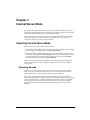
Connecting to a Computer Sequencer
If you have a computer with a MIDI interface and MIDI sequencing software, your
Stage Piano can become an integral part of a home MIDI recording studio. The basic
connection pattern is shown below.
Computer
Mixer
Sound Card
MIDI
Out
Audio
In
In
Out
L
Mode Select / Param Edit
Global
Grand Pno 1
Grand Pno 2
Reverb Wet / Dry
Chorus Wet / Dry
Local
Stereo
A Ribbon
Hold or Center
Touch
MIDI Channel
Destination
B Ribbon Up
Hold or Zero
Effect
Intemal Effect
B Ribbon Down
Hold or Zero
MIDI In
Intemal Sound
MIDI Program
Internal/Steup
MIDI Bank Sel Lo
MIDI Bank Sel Hi
Row Select
Internal Voices
1
Stage Pno 1
Stage Pno 2
2
1
Trem Dig EP
R
Zone
Key Range Lo
Key Range Hi
Play
Edit
Transpose
Velocity Curve
St Hard EP
6
Control Slider
Control Pedal
Set Chg Chan
Switch Pedal R
Switch Pedal L
Tune
Bright Pno
Sustain Pno
3
3
2
L
MIDI Prog Chg
Store
4
Digital EP
Dig EP & Str Pad
7
Piano & Str 1
Piano & Str 2
4
5
6
Rock Org 1
Rock Org 2
8
A
Tack Piano
Tite E Grand
5
7
9
8
10
Ballad Org 1
Ballad Org 2
Perc Org
Org & Piano
9
Bright E Grand
Warm E Grand
Dyno EP
Hard Dyno EP
No
Yes
11
13
15
12
0
Classic EP
Dig E Grand
Ld/Dmp
Fast Str 1
Fast Str 2
+/-
14
Touch Str
St Slo Strings
Cancel
16
St Slo Str Pad
Slow Dig Pad
SP88
Built-In Effects
Award Winning Soungs
Flexible MIDI Controller
Enter
MIDI Setups
17
19
21
23
25
27
29
31
18
20
22
24
26
28
30
32
Destinations:
0 - Bank Select MSB
R
Sound / Setup Select
Parameter
Panic
Volume / Controller
Stage Piano
Effects:
10 - Pan
16 to 19 - Gennral Control 1 to 4
65 - Portamento Switch
70 - Sound Variation
75 to 79 - Sound Control 6 to 10
92 - Effects 2 Depth
97 - Data Decrement
1 - Modulation Wheel
6 - Data Entry MSB
11 - Expression
20 to 31 - Undefined
66 - Sostenuto Pedal
71 - Timbre Control
80 tp 83 - General Control 5 to 8
93 - Chorus Depth
98 - Non-Reg Parm LSB
120 to 127 - Channel Mode Set
1 - Room & Chorus
6 - Bright Hall & Chorus
2 - Breath Controller
7 - Volume
5 - Portamento Time
12 - Effect Control 1
32 - Bank Select LSB
67 - Soft Peal
72 - Release Time
84 - Portamento Control
94 - Effects 4 Depth
99 - Non-Reg Parm MSB
102 to 119 - Undefined
128 - Send as Pitch Bend
2 - Bright Room & Chorus
0 - None
7 - Large Hall & Chorus
5 - Hall & Chorus
3 - Undefined
4 - Foot Controller
8 - Balance
9 - Undefined
13 - Effect Control 2
14 to 15 - Undefined
33 to 63 - LSB for 1 to 31
64 - Sustain Pedal
68 - Legato Switch
69 - Hold Pedal
73 - Attack Time
74 - Brightness
85 to 90 - Undefined
91 - Reverb Depth
95 - Effects 5 Depth
96 - Data Increment
100 - Registered Parm LSB
101 - Registered Parm MSB
129 - Send as Pressure
101 - Registered Parm MSB
4 - Bright Stage & Chorus
4 - Foot Controller
8 - Large Bright Hall & Chorus
9 - Deep Space
B
Figure 2-6
MIDI Connections: Computer and Sound Card
The cable from the Stage PianoÕs MIDI Out to the ComputerÕs MIDI In allows the
sequencing software to ÒhearÓ and record what you are playing. Likewise the cable
from the computerÕs MIDI Out to the Stage PianoÕs MIDI In allows the computer to
ÒplayÓ the sounds of your Stage Piano.
NOTE: Depending on the sound card or MIDI interface in your computer, you may need to
buy a special cable to make MIDI connections. See the manual that came with your computer
or sound card.
When using a sequencer, you need to make two important conÞguration settings to
avoid doubled notes when you are playing. First, the Local parameter (one of the
global parameters) should be set to a value of Off. This disconnects the internal path
from the keyboard (and other controls) to the sounds. Also you should be sure that
nrm) to avoid creating a MIDI
MIDI In (another global parameter) is set to Normal (n
loop. If youÕre just starting out, that shouldnÕt be a problem because nrm is the
default setting. See page Local Control Off and Patch Thru On on page 6-3 for
information about changing the values of the Local and MIDI In parameters.
Second, the sequencer should be set to Through mode which means that it passes on
what it hears at the computerÕs MIDI input to the computerÕs MIDI output. From
there the MIDI signal goes to the Stage PianoÕs MIDI input where it will activate the
sounds. If the sequencer is not in Through mode, you wonÕt hear anything as you play
the Stage Piano.
2-8
Getting Started
Connecting MIDI
NOTE: Different sequencer applications use different terms for what weÕre calling Through
mode. For example, the sequencer may have a Patch Thru or Soft Thru parameter, which you
should set to On in this case.
If you want to use an external sound module with your Stage Piano and a sequencer, it
should be connected into the loop before the Stage Piano, as illustrated below:
Computer
Sound Card
MIDI
Audio
In
MIDI
Out
Thru
In
Module B
In
Out
Mode Select / Param Edit
Sound / Setup Select
Parameter
Global
Grand Pno 1
Panic
Grand Pno 2
Intemal Sound
MIDI Program
Volume / Controller
Internal/Steup
MIDI Bank Sel Lo
MIDI Bank Sel Hi
Row Select
Reverb Wet / Dry
Chorus Wet / Dry
Local
Stereo
A Ribbon
Hold or Center
Touch
B Ribbon Up
Hold or Zero
Effect
Internal Voices
1
Stage Pno 1
Stage Pno 2
2
1
Trem Dig EP
R
Zone
Play
Edit
Intemal Effect
B Ribbon Down
Hold or Zero
Key Range Lo
Key Range Hi
Control Slider
Control Pedal
Set Chg Chan
Switch Pedal R
Switch Pedal L
Tune
Transpose
Velocity Curve
St Hard EP
MIDI In
6
Bright Pno
Sustain Pno
3
3
2
MIDI Channel
Destination
L
MIDI Prog Chg
Store
7
Piano & Str 1
Piano & Str 2
4
5
4
Digital EP
Dig EP & Str Pad
8
17
19
18
20
5
A
11
10
Perc Org
Org & Piano
9
Bright E Grand
Warm E Grand
Ld/Dmp
9
8
Ballad Org 1
Ballad Org 2
12
0
Fast Str 1
Fast Str 2
+/-
21
23
25
22
24
26
Destinations:
0 - Bank Select MSB
Tack Piano
Tite E Grand
7
6
Rock Org 1
Rock Org 2
Classic EP
Dig E Grand
No
Dyno EP
Hard Dyno EP
Yes
13
15
14
Touch Str
St Slo Strings
Cancel
16
St Slo Str Pad
Slow Dig Pad
SP88
Built-In Effects
Award Winning Soungs
Flexible MIDI Controller
Enter
MIDI Setups
27
29
31
28
30
32
Stage Piano
Effects:
5 - Portamento Time
10 - Pan
16 to 19 - Gennral Control 1 to 4
65 - Portamento Switch
70 - Sound Variation
75 to 79 - Sound Control 6 to 10
92 - Effects 2 Depth
97 - Data Decrement
102 to 119 - Undefined
0 - None
5 - Hall & Chorus
1 - Modulation Wheel
6 - Data Entry MSB
11 - Expression
20 to 31 - Undefined
66 - Sostenuto Pedal
71 - Timbre Control
80 tp 83 - General Control 5 to 8
93 - Chorus Depth
98 - Non-Reg Parm LSB
2 - Breath Controller
7 - Volume
12 - Effect Control 1
32 - Bank Select LSB
67 - Soft Peal
72 - Release Time
84 - Portamento Control
94 - Effects 4 Depth
99 - Non-Reg Parm MSB
128 - Send as Pitch Bend
2 - Bright Room & Chorus
7 - Large Hall & Chorus
3 - Undefined
4 - Foot Controller
8 - Balance
9 - Undefined
13 - Effect Control 2
14 to 15 - Undefined
33 to 63 - LSB for 1 to 31
64 - Sustain Pedal
68 - Legato Switch
69 - Hold Pedal
73 - Attack Time
74 - Brightness
85 to 90 - Undefined
91 - Reverb Depth
95 - Effects 5 Depth
96 - Data Increment
100 - Registered Parm LSB
101 - Registered Parm MSB
129 - Send as Pressure
101 - Registered Parm MSB
4 - Bright Stage & Chorus
4 - Foot Controller
8 - Large Bright Hall & Chorus
9 - Deep Space
120 to 127 - Channel Mode Set
1 - Room & Chorus
6 - Bright Hall & Chorus
B
Figure 2-7
MIDI Connections: Computer and Sound Module
2-9
Getting Started
Connecting MIDI
Full System
Even more complex setups are possible. Below is just one possibility using a Kurzweil
ExpressionMate MIDI processor and K2600R to provide unprecedented expressive
control over a vast palette of sounds.
Computer
MIDI
Processor
Sound Module
ExpressionMate
Sound Card
MIDI
Audio
In
Out
In
Thru
Out
In
In
Out
Mode Select / Param Edit
Sound / Setup Select
Parameter
Global
Grand Pno 1
Panic
Grand Pno 2
Intemal Sound
MIDI Program
Volume / Controller
Internal/Steup
MIDI Bank Sel Lo
MIDI Bank Sel Hi
Row Select
Reverb Wet / Dry
Chorus Wet / Dry
Local
Stereo
A Ribbon
Hold or Center
Touch
Internal Voices
1
Stage Pno 1
Stage Pno 2
2
1
MIDI Prog Chg
Store
MIDI Channel
Destination
B Ribbon Up
Hold or Zero
Intemal Effect
B Ribbon Down
Hold or Zero
MIDI In
Key Range Lo
Key Range Hi
Control Slider
Control Pedal
Set Chg Chan
Switch Pedal R
Switch Pedal L
Tune
Play
Edit
Trem Dig EP
Transpose
Velocity Curve
3
Piano & Str 1
Piano & Str 2
4
5
4
St Hard EP
6
Digital EP
Dig EP & Str Pad
7
Rock Org 1
Rock Org 2
8
5
A
11
10
Perc Org
Org & Piano
9
12
0
Fast Str 1
Fast Str 2
+/-
17
19
21
23
25
18
20
22
24
26
Classic EP
Dig E Grand
No
Dyno EP
Hard Dyno EP
Yes
13
15
14
Touch Str
St Slo Strings
Cancel
16
St Slo Str Pad
Slow Dig Pad
SP88
Built-In Effects
Award Winning Soungs
Flexible MIDI Controller
Enter
27
29
31
28
30
32
Stage Piano
Effects:
10 - Pan
16 to 19 - Gennral Control 1 to 4
11 - Expression
20 to 31 - Undefined
2 - Breath Controller
7 - Volume
12 - Effect Control 1
32 - Bank Select LSB
3 - Undefined
4 - Foot Controller
8 - Balance
9 - Undefined
13 - Effect Control 2
14 to 15 - Undefined
33 to 63 - LSB for 1 to 31
64 - Sustain Pedal
0 - Bank Select MSB
Bright E Grand
Warm E Grand
Ld/Dmp
9
8
Ballad Org 1
Ballad Org 2
MIDI Setups
Destinations:
1 - Modulation Wheel
Tack Piano
Tite E Grand
7
6
Effect
R
Zone
Bright Pno
Sustain Pno
3
2
L
5 - Portamento Time
6 - Data Entry MSB
65 - Portamento Switch
70 - Sound Variation
66 - Sostenuto Pedal
71 - Timbre Control
80 tp 83 - General Control 5 to 8
67 - Soft Peal
72 - Release Time
84 - Portamento Control
68 - Legato Switch
69 - Hold Pedal
73 - Attack Time
74 - Brightness
85 to 90 - Undefined
91 - Reverb Depth
75 to 79 - Sound Control 6 to 10
102 to 119 - Undefined
0 - None
5 - Hall & Chorus
92 - Effects 2 Depth
97 - Data Decrement
93 - Chorus Depth
98 - Non-Reg Parm LSB
94 - Effects 4 Depth
99 - Non-Reg Parm MSB
128 - Send as Pitch Bend
2 - Bright Room & Chorus
7 - Large Hall & Chorus
95 - Effects 5 Depth
96 - Data Increment
100 - Registered Parm LSB
101 - Registered Parm MSB
129 - Send as Pressure
101 - Registered Parm MSB
4 - Bright Stage & Chorus
4 - Foot Controller
8 - Large Bright Hall & Chorus
9 - Deep Space
120 to 127 - Channel Mode Set
1 - Room & Chorus
6 - Bright Hall & Chorus
B
Figure 2-8
MIDI Connections: Compute, Module, Processor
With this setup, note signals from the Stage Piano Þrst pass through the
ExpressionMate where they can be processed into additional zones, have automatic
arpeggiation added to them, or be processed in other ways as well. MIDI signals from
the Stage PianoÕs controllers are also modiÞed and combined with the
ExpressionMateÕs own unique controls. Note and control signals then travel to the
computer where they can be optionally recorded, then Þnally to the K2600R module
and the Stage PianoÕs internal sound module. As always when using with a computer
sequencer, set the Stage PianoÕs Local parameter to Off. See Example: The Kurzweil
ExpressionMate on page 6-6 for more about what this example system can do.
2-10
Getting Started
The Front Panel
The Front Panel
The Stage PianoÕs front panel is illustrated in detail below.
Control
Slider
Info
Strip
Editing
Buttons
Parameter
Display
Mode Select / Param Edit
Mode
LEDs
Numeric
Display
Sound / Setup Select
Parameter
Global
Grand Pno 1
Panic
Grand Pno 2
Intemal Sound
MIDI Program
Volume / Controller
Internal/Steup
MIDI Bank Sel Lo
MIDI Bank Sel Hi
Row Select
MIDI Channel
Destination
L
MIDI Prog Chg
Store
Reverb Wet / Dry
Chorus Wet / Dry
Local
Stereo
A Ribbon
Hold or Center
Touch
B Ribbon Up
Hold or Zero
Internal Voices
1
Play
Edit
2
Bright Pno
Sustain Pno
3
Piano & Str 1
Piano & Str 2
4
5
Bright E Grand
Warm E Grand
Ld/Dmp
Classic EP
Dig E Grand
No
Dyno EP
Hard Dyno EP
Yes
5
7
9
11
13
4
6
8
10
12
14
16
Ballad Org 1
Ballad Org 2
Perc Org
Org & Piano
Touch Str
St Slo Strings
St Slo Str Pad
Slow Dig Pad
Intemal Effect
B Ribbon Down
Hold or Zero
MIDI In
Key Range Lo
Key Range Hi
Control Slider
Control Pedal
Set Chg Chan
Switch Pedal R
Switch Pedal L
Tune
St Hard EP
6
Digital EP
Dig EP & Str Pad
7
Rock Org 1
Rock Org 2
8
9
0
Fast Str 1
Fast Str 2
+/-
Cancel
15
Enter
MIDI Setups
17
19
18
20
21
23
25
22
24
26
Destinations:
Figure 2-9
Tack Piano
Tite E Grand
3
2
Trem Dig EP
Transpose
Velocity Curve
Stage Pno 1
Stage Pno 2
1
Effect
R
Zone
Sound / Setup
Select Buttons
27
28
29
31
30
32
Effects:
0 - Bank Select MSB
5 - Portamento Time
10 - Pan
16 to 19 - Gennral Control 1 to 4
65 - Portamento Switch
70 - Sound Variation
75 to 79 - Sound Control 6 to 10
92 - Effects 2 Depth
97 - Data Decrement
102 to 119 - Undefined
0 - None
5 - Hall & Chorus
1 - Modulation Wheel
6 - Data Entry MSB
11 - Expression
20 to 31 - Undefined
66 - Sostenuto Pedal
71 - Timbre Control
80 tp 83 - General Control 5 to 8
93 - Chorus Depth
98 - Non-Reg Parm LSB
120 to 127 - Channel Mode Set
1 - Room & Chorus
6 - Bright Hall & Chorus
2 - Breath Controller
7 - Volume
12 - Effect Control 1
32 - Bank Select LSB
67 - Soft Peal
72 - Release Time
84 - Portamento Control
94 - Effects 4 Depth
99 - Non-Reg Parm MSB
128 - Send as Pitch Bend
2 - Bright Room & Chorus
7 - Large Hall & Chorus
3 - Undefined
4 - Foot Controller
8 - Balance
9 - Undefined
13 - Effect Control 2
14 to 15 - Undefined
33 to 63 - LSB for 1 to 31
64 - Sustain Pedal
68 - Legato Switch
69 - Hold Pedal
73 - Attack Time
74 - Brightness
85 to 90 - Undefined
91 - Reverb Depth
95 - Effects 5 Depth
96 - Data Increment
100 - Registered Parm LSB
101 - Registered Parm MSB
129 - Send as Pressure
101 - Registered Parm MSB
4 - Bright Stage & Chorus
4 - Foot Controller
8 - Large Bright Hall & Chorus
9 - Deep Space
Stage Piano Front Panel
Sound and Setup Select Buttons
To the right of the display are the 16 sound and setup select buttons. When in Internal
Voices mode (indicated by the LED over the display being on), each button can select
the two sounds named in the label above the button. Press a button the Þrst time, itÕll
glow red, and youÕll get the ÒredÓ sound (the sound thatÕs in the row that has a red
arrow pointing to it). Press the same button again; it will turn green, and youÕll get the
green sound. In this way you can very quickly select any of the Stage PianoÕs 32 builtin sounds (voices).
When in MIDI Setups mode (indicated by the LED under the display being on), these
same buttons allow you to select one of 32 possible MIDI Setups. For these, youÕll
want to use the numbers under the button; odd for red and even for green. Note that
the sound associated with each setup is programmable and may be different from the
sound named on the button.
In Edit mode (indicated by some of the LEDs to the left of the display being on), the
sound or setup is frozen and these buttons serve a variety of data entry functions as
marked on the buttons themselves. Refer to Chapter 3 for details on their use with the
editors.
The Numeric Display
The numeric display is in the center of the panel and is better described as a 3character display because sometimes it will also display stylized letters. The display
shows 4 kinds of information depending on mode as follows:
1.
In Internal Voices Play mode, it shows the current Sound Number, 1Ð32.
2.
In MIDI Setups Play mode, it shows the current Setup Number, also 1Ð32.
3.
In Edit mode, it shows the current parameter value, which may be a positive
number, a negative number, or a string of 3 characters depending on the
parameter.
4.
Sometimes, regardless of mode, the display may show a message or even ask a
question.
2-11
Getting Started
The Front Panel
Each character in the display also has a small dot at the bottom right. If these dots are
on, it means that the current setup has been edited but the change has not yet been
made permanent by storing it into memory.
Mode LEDs
The two fundamental modes of the Stage Piano are Internal Voices mode and MIDI
Setups mode. The mode LEDs above and below the display indicate which mode is
current. One of them will always be on. Internal Voices Play mode is always selected
when you Þrst turn your Stage Piano on.
Parameter Editing Buttons
The 4 parameter-editing buttons are to the left of the display; most of them have dual
markings. The top marking is active when in Play mode and the bottom marking
when in Edit mode. One exception is Row Select, whose single marking is for Edit
mode. The Play/Edit button is used to shift between Play mode and Edit mode.
The Parameter Display
Your Stage Piano has a total of 30 parameters, whose values determine sound selection,
effects, what the player controls do, keyboard split, and a host of other options. The
active parameter is indicated by 8 LEDs arranged around a list of the 30 parameter
names.
The 30 parameters are arranged into 3 columns. The two column-designator LEDs
identify the active column as follows:
Left column LED on
Left parameter column is active
Right column LED on
Center parameter column is active
Both column LEDs off Right (global) parameter column is active
Each column of parameters has 6 rows of (usually) two paired parameters each.
Each column of parameters consists of 6 rows, with two parameters for each row
(except for the Effect parameter). There is a row-designator LED for each pair. If the
row LED is on continuously, the upper parameter of the pair is active. If the row LED
is blinking, then the lower parameter of the pair is active. The LED for the Efect
parameter (left column, 4th row) always lights continuously when the Effect
parameter is selected.
Use the Col Select and Row Select buttons to navigate to the parameter that you want
to view or edit.
The Info Strip
This long strip below all of the buttons, LEDs, and display contains useful reference
information. Most of the strip tells what each of the 128 possible MIDI destination
numbers does. The remainder lists the 10 effects by number and name. Chapters 3
and 4 tell you how to use the information on the strip.
2-12
Getting Started
The Front Panel
Button Combinations
How many ways can you press a button? Actually the Stage Piano recognizes 3 special
cases beyond just Òpressing a button.Ó
Direct Select
In Play mode, if you want the red sound or odd-numbered setup next, itÕs simpleÑ
just press the corresponding sound/setup select button. Two presses, however, are
required to get a green sound or setup. There may be cases where youÕd prefer to skip
the Þrst (red or odd) selection and go directly to the second. So, if you press the same
sound select button, twice, rapidly (like double-clicking a computer mouse), the
intermediate selection will be skipped.
Panic
Simultaneously pressing the two buttons labeled Panic will start transmitting the panic
sequence, which is a kind of ÒMIDI resetÓÑthis will silence all sounding notes, turn
sustain off, and so forth. Regardless of how long you hold the buttons, the minimum
effective sequence will be sent (as described below). If you continue to hold them, a
more elaborate (and more effective) sequence is sent. As long as the sequence is being
sent, all of the parameter LEDs will light.
Here is the panic sequence:
1.
All Notes Off, All Sound Off, Reset All Controllers to the internal sound
module.
2.
All Notes Off, All Sound Off, Reset All Controllers sent to the MIDI output on
all 16 MIDI channels.
3.
Individual Note Off messages sent to the MIDI output for all possible audible
notes on all MIDI channels.
4.
Present position of Stage Piano controls according to the current setup.
Steps 1 and 2 are always sent completely no matter how long the Panic buttons are
held; this takes only a fraction of a second. Step 3 starts with low notes on Channel 1,
progresses to higher notes, then moves on to Channel 2, etc. until you release the Panic
buttons or the sequence is complete (about 3 seconds). Note that note numbers 0Ð11,
which are not audible and perform special functions on some modules, are not
affected by the panic sequence.
As soon as you release the Panic buttons, all player control positions get refreshed,
according to the current setup. This takes only a fraction of a second, and it happens
even if the entire panic sequence hasnÕt been sent.
Demo Song
If you press the two left-most edit buttons simultaneously when in Play mode, the
short demo song will start to play. Release the buttons once the song starts playing.
You can stop the demo song before it ends by pressing any other button. While the
demo song is playing, the display will sequentially show dmo, sng, pla.
2-13
Getting Started
What Mode Am I In?
What Mode Am I In?
WeÕve used the word ÒmodeÓ quite a bit in this chapter. Here is a reference list of all of
the possible modes and how to recognize them. The signiÞcance of the modes will
become clear as you read on through Chapters 3 and 4.
Mode
How to Recognize it
What You Can Do
Internal Voices,
Play
Internal Voices LED on, all
others off; display shows
sound number
Directly select
which of 32 sounds
to play
MIDI Setups,
Play
MIDI Setups LED on, all
others off; display shows
setup number
Directly select
which of 32 MIDI
setups to use
Internal Voices,
Edit
Internal Voices LED, 1 or 2
Parameter Select LEDs on;
display shows parameter
value
Select parameter to
edit and change its
value
MIDI Setups,
Edit
MIDI Setups LED, 1 or 2
Parameter Select LEDs on;
display shows parameter
value
Select parameter to
edit and change its
value
Number Entry
Display shows number
being entered, blinking
Use Sound/Setup
Select buttons to
enter digits, accept
entry, or cancel
Query
Display sequentially shows
2 or more abbreviated
words as a question
Use Up arrow (Yes),
Down arrow (No),
or Cancel buttons
to answer the query
Table 2-1
2-14
Stage Piano Modes
Chapter 3
Internal Voices Mode
This chapter describes Internal Voices mode in detail. This is the simpler of the two
modes and is automatically selected when power is turned on. Internal Voices mode is
indicated by the LED immediately over the display being on.
When in Internal Voices mode, the entire keyboard plays the selected sound. MIDI
signals can also be sent so that an external sound module can Òplay along,Ó or a
computer sequencer can record your performance.
Selecting Internal Voices Mode
There are two ways to get to Internal Voices mode:
¥ If the Stage Piano is in Play mode (no LEDs to the left of the display are lit), simply
press the upper-left editing button (marked Internal/Setup).
¥ If the Stage Piano is in Edit mode (LEDs to the left of the display are lit), press the
lower right editing button (marked Play/Edit). This returns the Stage Piano to Play
mode; all LEDs to the left of the display should turn off. If not, press Play/Edit
repeatedly until they do. Then press Internal/Setup.
When successful, the LED above the display marked Internal Voices will light. Of
course, turning the power switch off then on again will always return to Internal
Voices mode.
Selecting Sounds
To select a sound for playing, simply locate its name and press the corresponding
button once if itÕs a red sound, or twice if itÕs green). In case the buttonÕs LED is
already on but is the wrong color, press the button once to change it.
Keys (or the sustain pedal) may be down when selecting the new sound. Notes
already playing at the time a different sound is selected will continue to play using the
previous sound. If the new sound has a different effects setting, however, the effects
will change when the new sound is selected. This may or may not be noticeable,
depending on the contrast between the two effects. Read on for more on effects
settings.
Internal Voices Mode
Selecting Internal Voices Mode
Modifying Effects
To change the effect type or intensity of the currently selected sound, you will need to
make a brief excursion into Edit mode. Do the following to temporarily change the
effect setting of a sound:
1.
Press the Play/Edit button once if in Play mode. This enters Edit mode.
2.
Select the left column of parameters by pressing the Col Select button until the
left-column LED lights. At most 2 presses will be required.
3.
Select the Effect parameter by pressing the Row Select button repeatedly until
the Effect-parameter LED lights. If you go past it, just keep pressing and the
LED sequence will continue from the top.
4.
The display should show a number between 0 and 9. This is the number of the
current effect. Check the right end of the Info Strip to Þnd out the
corresponding name.
5.
To choose a different effect type, either use the Up/Down arrow buttons (in the
Sound Select section) to scroll through the 10 possibilities, or press one of the
digit buttons then the Enter button.
This procedure selects a different effect type. Use a similar procedure to adjust only the
intensity of the existing effectÕs reverberation and/or chorus components (this is called
the wet/dry mix; wetter is more intense):
1.
Go to Edit mode, select the center column of parameters, and select either
Reverb Wet/Dry or Chorus Wet/Dry (the top-row LED will light if you select
Reverb; it will blink if you select Chorus). Remember that when there are two
parameters for the same LED, the lower one always corresponds to a blinking
LED.
2.
The display should show a number between 0 (inaudible) and 100 (maximum).
This is the percent proportion of the effect.
3.
Either use the Up/Down arrow buttons (in the Sound Select section) to scroll
through the values, or press one of the digit buttons then the Enter button.
Check out Editing Basics on page 3-6 for more about editing. When Þnished editing the
effects for the current sound, press Play/Edit to return to play mode. Note that the
effects changes just described are temporary; they will be forgotten when changing to
another sound. To have them remembered, read on.
3-2
Internal Voices Mode
Saving a Sound’s Effects Settings
Saving a Sound’s Effects Settings
1.
Go to Edit mode and select one of the 3 effects parametersÑEffect (left column,
4th row), Reverb Wet/Dry (right column, 1st row upper), or Chorus Wet/Dry
(right column, 1st row lower). If youÕre not sure how to select parameters, see
Modifying Effects on page 3-2 for an example.
ItÕs important to select one of these 3 parameters, because doing so tells the
Stage Piano that you want to save only the effects settings for the current
sound, and nothing else. If you select one of the other parameters, executing a
save will save the Internal Voices Setup, which includes MIDI control
information.
2.
Press the Store button (the bottom-left button in the Edit Group).
3.
The display will sequentially show snd, sa/, which means ÒSave the
soundÕs effect?Ó If it shows 1nt, su, sa/,youÕre about to save the
Internal Voices Setup, which is not what you want to do. In this case, press
Cancel, and go back to Step 1. Be sure one of the 3 effects parameters (Internal
Effect, Reverb Wet/Dry, or Chorus Wet/Dry) is selected, then try again. This
ensures that all youÕre doing is associating a particular effect to a particular
sound. Saving the Internal Voices Setup saves additional information, like the
MIDI channel used by the sound.
4.
Press the Up arrow (Yes) button (Sound Select Group) or Store button to
execute the save. If you change you mind, press the Down arrow (No) button
or Cancel instead.
5.
The display will ßicker brießy while the current effect number and intensity
settings for the current sound are saved in EEPROM memory.
Now, whenever this sound is selected, the internal effects will change to the settings
you just saved.
Modifying The MIDI Transmit Channel
When in Internal Voices mode, anything you play is also sent to the MIDI Out port,
which can be connected to external sound modules, a synthesizer, or a computer. By
default, the MIDI signals are transmitted on Channel 1 but you may need to change
that to match the channel your external device is ÒlisteningÓ to. Do this to change the
MIDI transmit channel:
1.
Go to Edit mode, and select the MIDI Channel parameter (left column, third
parameter; the LED should be on, not blinking). If youÕre not sure how to select
parameters, see Modifying Effects on page 3-2 for an example.
2.
Use the Up or Down arrow buttonsÑor the digit buttons plus EnterÑto
change to a new channel between 1 and 16.
The next notes or control movements you make will be sent on the new MIDI channel.
The MIDI channel change is temporary. To make it permanent for Internal Voices
mode, press the Store button twice.
CAUTION: If you change the MIDI channel while holding keys or the sustain pedal down,
those notes may become Òstuck.Ó To silence them, press both buttons labeled Panic at the same
time and hold until the stuck notes are silenced. Many LEDs will light while the panic
sequence is sent.
3-3
Internal Voices Mode
Sending a MIDI Program Change
Sending a MIDI Program Change
You can change the program (sound) in an external device from the front panel of your
Stage Piano quickly and easily without leaving Play mode:
1.
While in Play mode, press the MIDI Prog Chg (MIDI Program Change)
buttonÑitÕs the lower-left editing button. The display will change to the last
sent program number (or Ñ if none).
2.
Enter the desired new program number (1Ð128) by using the Up or Down
arrow buttons Ñor the digit buttons.
3.
When the desired number is showing, press the Enter button. Press Cancel
instead if you decide not to send a program change. A MIDI Program Change
command will be sent on the current MIDI Transmit Channel. The new
program number will persist in the display brießy, then it will revert to the
current Internal Voice selection.
The next notes you play will be the newly selected sound in your external module.
Depending on the external moduleÕs design, notes that were sounding just before the
program change was sent may either be unaffected, cut off, or take on some
characteristics of the newly selected sound.
Just as opinions differ on whether 2000 or 2001 is the millennium year, some modules
begin numbering their programs at zero while others begin at 1. The former type will
switch to a program number thatÕs 1 lower than you specify.
Modifying Other Internal Voice Parameters
Internal Voices mode is really a special MIDI Setup with a number of parameters
governing what happens when you select Internal Voices mode, and how your
keystrokes and control movements are interpreted and sent. This section describes the
parameters used by Internal Voices mode. More detail can be found in Chapter 4,
which describes MIDI Setups in general. However, even if you are not using MIDI,
many of these parameters will still affect the internal sound module.
NOTE: Some parameters marked on the front panel are not relevant to Internal Voices mode,
and cannot be selected for examination or editing.
MIDI Program
1–128 and Off
SpeciÞes the MIDI Program Change number sent whenever changing to Internal
Voices mode. Off means do not send a program change.
MIDI Bank Sel Lo
0–127 and Off
SpeciÞes the MIDI Bank Select number(s) sent in conjunction with MIDI Program
Change to further specify the program desired. See MIDI Bank Sel Lo, MIDI Bank Sel
Hi on page 4-4 for more about Bank Select.
3-4
Internal Voices Mode
Modifying Other Internal Voice Parameters
MIDI Channel
1-16 and Off
SpeciÞes which MIDI channel to send on. No MIDI signals are sent if the value is Off.
Destination
Int, Mid, Bot
This speciÞes where your performance data should be sent. Int means the internal
sound module, Mid means MIDI, and Bot means both.
Internal Effect
0-9, Noc
This is the effect number for the currently-selected sound. A value of 0 means no
effect, and Noc (no change) means the effect doesnÕt change when this sound is
selected. As you select different sounds, the value of this parameter will change.
Transpose
-60 to 60
Subtracts or adds the speciÞed number of semitones to the notes you play. Caution:
changing this parameter while keys are down may cause stuck notes.
Velocity Curve
1-8
Allows you to alter the relationship between keyboard playing effort (keystroke
velocity) and the resulting sound volume (for velocity sensitive voices). 1 is normal.
See page 4-11, and Velocity Curve on page 4-6 for more.
Reverb Wet/Dry, Chorus Wet/Dry
0-100, Noc
This is the effect intensity for the currently-selected sound. Noc means that the effect
intensity doesnÕt change when this sound is selected.
A Ribbon
0-129, Off
SpeciÞes where signals from the left ribbon are sent. See the Info Strip for
corresponding MIDI controller names. Default is Pitch Wheel, which the internal
sound module does not respond to.
Hold or Center
Hld, Ctr
SpeciÞes whether the A ribbon signal remains at its last value or returns to center
when your Þnger is lifted. Default is Center (Ctr).
B Ribbon Up, B Ribbon Down
0-129 and Off
SpeciÞes where signals from the two halves of the right ribbon are sent. Defaults are
Modulation Wheel (01) and Pan (10) respectively. Some sounds will respond to
modulation but none will respond to Expression.
3-5
Internal Voices Mode
Editing Basics
Hold or Zero
Hld, Zro
SpeciÞes whether the B ribbon signal remains at its last value or returns to zero when
your Þnger is lifted. Default is Hold.
Control Slider, Control Pedal
0-129 and Off
SpeciÞes where signals from the front panel Volume/Controller slider and control
pedal are sent. Defaults are Volume and Foot Controller. The internal sound module
does not respond to Foot Controller signals.
Switch Pedal R, Switch Pedal L
0-129 and Off
SpeciÞes where signals from the two possible switch pedals go. Defaults are Sustain
Pedal and Sostenuto Pedal. The standard single switch pedal functions as Switch
Pedal R.
You can examine and change the values of any of these parameters using the same
procedure as Modifying MIDI Transmit Channel above except modify the Þrst step to
select the parameter of interest. And you can save your changes by selecting any noneffects parameter, then press Store. YouÕll see int, su, sa/ when you do.
Read on for more about editing and saving parameters.
Editing Basics
The way the Stage Piano responds to your playing and control movements is
determined by the setting or value of various parameters. Editing is changing those
values and thus changing the Stage PianoÕs response to your playing. You can use
similar procedures to examine the current values of parameters without changing
them.
Below is a drawing of the front panel pointing out the main groupings of buttons and
displays that you use to edit. The following sections will refer to these groupings
frequently so it pays to become familiar with them.
C0l / Row
Select
Mode Select / Param Edit
Parameter Area
Column LEDs
Sound / Setup Select
Parameter
Global
Grand Pno 1
Panic
Grand Pno 2
Reverb Wet / Dry
Chorus Wet / Dry
Local
Stereo
A Ribbon
Hold or Center
Touch
MIDI Channel
Destination
B Ribbon Up
Hold or Zero
Effect
Intemal Effect
B Ribbon Down
Hold or Zero
MIDI In
Key Range Lo
Key Range Hi
Control Slider
Control Pedal
Set Chg Chan
Switch Pedal R
Switch Pedal L
Tune
Intemal Sound
MIDI Program
Internal/Steup
MIDI Bank Sel Lo
MIDI Bank Sel Hi
Row Select
L
Store
Figure 3-1
3-6
Internal Voices
1
Play
Edit
Transpose
Velocity Curve
Mode
Select
Row
LEDs
Stage Pno 1
Stage Pno 2
2
Bright Pno
Sustain Pno
3
Piano & Str 1
Piano & Str 2
4
Tack Piano
Tite E Grand
5
Bright E Grand
Warm E Grand
Classic EP
Dig E Grand
Ld/Dmp
No
Dyno EP
Hard Dyno EP
Yes
1
3
5
7
9
11
13
2
4
6
8
10
12
14
16
Ballad Org 1
Ballad Org 2
Perc Org
Org & Piano
Touch Str
St Slo Strings
St Slo Str Pad
Slow Dig Pad
Trem Dig EP
R
Zone
MIDI Prog Chg
Store
Display
St Hard EP
6
Digital EP
Dig EP & Str Pad
7
Rock Org 1
Rock Org 2
8
9
0
Fast Str 1
Fast Str 2
+/-
Cancel
15
Enter
MIDI Setups
Mode
LEDs
Stage Piano Front Panel
17
19
21
23
25
27
29
31
18
20
22
24
26
28
30
32
Sound / Setup Select
Internal Voices Mode
Editing Basics
Edit vs. Play Mode
In Play mode you select different sounds (or MIDI Setups if in MIDI Setups mode) by
pressing the Sound/Setup Select buttons to the right of the display. In Edit mode, the
sound (or setup) is frozen and the Sound/Setup Select buttons perform a variety of
editing functions as marked on the buttons themselves. That is really the main
differenceÑyou can play the keyboard and controls equally well in either mode.
In Play mode, the display shows the sound (or setup) number. A bi-color LED in one
of the Sound/Setup Select buttons also indicates the current sound (or setup). All of
the LEDs to the left of the display are off as well.
In Edit mode, the display shows the value of the currently selected parameter. LEDs to
the left of the display indicate which parameter is current. The current sound (or
setup) continues to be indicated in the Sound/Setup Select buttons.
The following assumes that you are in Edit mode.
Selecting a Parameter
The names of all 30 possible parameters are listed in the Parameters area. The listing is
in 3 columns (Left, Right, and Global) and 6 rows. In each column, there are 1 or 2
parameters per row.
The 2 column-designator LEDs indicate a column, either Left or Right. If both are off,
then the Global column is current.
The 6 row-designator LEDs indicate a row. If the LED is on continuously, then the
upper parameter of the pair is current. If it is blinking, the lower parameter is current.
To select a different column, press the Col Select button repeatedly until the column
LEDs indicate the desired column. Note that the current row LED may change from
blinking to continuous when you change to a column with only one parameter for the
current row.
To select a different row, press the Row Select button until the desired row and
parameter are selected. If you overshoot, just keep pressing and the row selection will
ÒwrapÓ from bottom to top again.
As you select different parameters, the display will change to show their value. If you
return to Play mode then later reenter Edit mode, you will Þnd that the parameter
selection is remembered.
Increment/Decrement Editing
The easiest way to change the value of the currently selected parameter is to use the
Up/Down buttons (the ones with the arrows on them) to cycle through all of the
possible values for the parameter. This is particularly effective when the parameterÕs
values are words like int, mid, and bot, but is also effective for small
changes in numerical values.
If you hold an arrow button down, its action will begin to repeat rapidly after a short
delay which will speed up larger changes.
3-7
Internal Voices Mode
Editing Basics
Direct Numerical Editing
Most parameters have numerical values which can also be entered directly using the
Sound/Setup Select buttons marked with digits. You can enter a 1, 2, or 3-digit value,
then press Enter to accept it. There are a couple of rules though:
¥ You cannot enter a value greater than 255. If you try, the current entry value will
revert to just the last digit entered.
¥ If you try to enter a value that is not valid for the current parameter (like 27 for the
Internal Effect), it will change to the closest valid value when you press Enter.
Once numeric entry has started by pressing the Þrst digit, the display will blink until
you press Enter to accept it or Cancel to abandon it. If the parameter has a signed
value, like Transpose or Tune, you can press the +/- button during numeric entry to
change the sign from positive (not indicated) to negative (Ð) and back.
Cancelling Edits
As mentioned above, you can cancel numeric entry of a new parameter value once itÕs
started (indicated by the blinking display) by pressing the Cancel button. The display
will change back to the parameterÕs value before numeric entry started.
You can also cancel all changes youÕve made to a parameterÕs value since you selected
it by pressing Cancel outside of numeric entry when the display is not blinking.
However, once you select a different parameter, the only way to recover the original
value of earlier selected parameters is to ÒreloadÓ the Internal Voices setup. Read on to
Þnd out how this is done.
Saving The Edited Parameters
Until you save your changes, they will remain in effect only until you change modes
(Internal Voices to MIDI Setups or back), change setups (when in MIDI Setups mode),
change sounds (if youÕve edited an internal effects parameter in Internal Voices mode)
or turn the power off. To save your changes in EEPROM memory so theyÕll come back
next time you select the same mode, setup, sound, or turn power on, use the following
general procedure:
1.
Be sure youÕre in Edit mode then press the Store button in the edit group.
2.
Depending on the mode and what parameter is selected, one of these query
sequences will appear in the display:
3.
3-8
Sequence
Meaning
int su sa/
Internal Voices Setup Save?
snd sa/
Sound: Effects Settings Save?
su sa/
MIDI Setup Save? (See Chapter 4)
gbl sa/
Global Parameters Save? (See Chapter 5)
To execute the save, press Up arrow (Yes) or Store. To cancel the save, press
Down arrow (No) or Cancel.
Internal Voices Mode
Editing Basics
You may have noticed that on return to Play mode after editing a non-effects
parameter, all of the dots in the display are lit. This is a signal that the Internal Voices
Setup has been edited but not yet saved. Executing the above save procedure will turn
them off.
If you attempt to change modes and the dots are on, youÕll see one of the query
sequences shown in Step 2 above, and you can do one of the following:
1.
Press Up arrow or Store to save before the mode change.
2.
Press Down arrow or Cancel to skip saving and continue with the mode
change.
3.
Press Cancel to abandon the mode change.
This is a safety feature to prevent accidental loss of your edits.
If you wish to abandon all of your edits since the last save, do this:
1.
Exit Edit mode (press the Play/Edit button).
2.
Change to MIDI Setups mode (press the Internal/Setup button).
3.
Answer No to the int su sa/ query (Down arrow).
4.
Change back to Internal Voices mode (press the Internal/Setup button again).
The Internal Voices Setup will be reloaded from EERPOM memory thus erasing all
edits since the last save.
3-9
Chapter 4
MIDI Setups Mode
Up to now youÕve been operating your Stage Piano exclusively in Internal Voices
mode (unless of course youÕre like most readers and have tried MIDI Setups mode
anyway). YouÕve learned that you can set the physical controllers, like ribbons and
pedals, to transmit to desired MIDI destination numbers; transpose the keyboard;
send a MIDI Program Change; specify the MIDI channel; and set the effects for each of
the 32 interval voices. This entire collection of information, along with a sound and an
effect, constitutes the Internal Voices Setup, which you can save in memory.
Now imagine 32 of these setups, each of which can have different parameter settings,
that can be called up at the press of a button. Then further imagine that each setup is
split into two parts, each of which has all of these setup parameters but is active only
over a part of the keyboard range. What you have imagined is MIDI Setups mode,
which weÕll explain next.
Selecting Setups
First youÕll need to switch to MIDI Setups mode. Check that all of the LEDs to the left
of the display are off meaning youÕre in Play mode. If they are not, press the Play/Edit
button until they go out. Next check the LED beneath the display labeled MIDI Setups.
If it is off, press the Internal/Setup button to change to MIDI Setups mode and
illuminate the LED. If the display shows a question about saving (like su sa/),
and you donÕt know what that means, refer to Saving The Edited
Parameters on page 3-8, or just press the No arrow button.
Now youÕre in MIDI Setups mode and can select different MIDI Setups the same way
you selected different sounds before. The sound associated with each MIDI Setup is
programmable, so it doesnÕt necessarily correspond to the labels above the Sound/Setup
Select buttons (although the factory-default MIDI Setups do correspond). For this
reason, itÕs good to think of MIDI Setups in terms of numbers (which are printed below
the buttons and shown on the display) rather than names. See below for more on the
sound and the two external MIDI programs that are associated with each MIDI Setup.
NOTE: The sound associated with a setup may be different from the name printed above its
select button.
One other note about selection of MIDI Setups: it may be important to avoid passing
through an intermediate setup when switching to an even-numbered (green) setup. By
performing the necessary two button presses rapidly, the Stage Piano logic will skip
the odd (red) setup entirely. Practice this a few times; youÕll be able to see whether the
red selection is skipped. You donÕt have to be super-quick; a tempo about like doubleclicking a computer mouse is sufÞcient.
MIDI Setups Mode
Zones
Zones
The biggest difference between the Internal Voices Setup and a MIDI Setup is that the
latter has 2 zones whereas the former has only 1. This name comes about from its usual
association with a split keyboard. In the Stage Piano, however, the zones can overlap
partially or even completely thus making the term layer more accurate. Nevertheless,
weÕll use Òzone.Ó Figure 4-1 should help you better understand the concept of zones.
Mode Select / Param Edit
Sound / Setup Select
Parameter
Global
Grand Pno 1
Panic
Grand Pno 2
Intemal Sound
MIDI Program
Volume / Controller
Internal/Steup
MIDI Bank Sel Lo
MIDI Bank Sel Hi
Row Select
Reverb Wet / Dry
Chorus Wet / Dry
Local
Stereo
A Ribbon
Hold or Center
Touch
B Ribbon Up
Hold or Zero
Effect
Internal Voices
1
Stage Pno 1
Stage Pno 2
2
1
MIDI Prog Chg
Store
Trem Dig EP
R
Zone
Play
Edit
Intemal Effect
B Ribbon Down
Hold or Zero
MIDI In
Key Range Lo
Key Range Hi
Control Slider
Control Pedal
Set Chg Chan
Switch Pedal R
Switch Pedal L
Tune
Transpose
Velocity Curve
St Hard EP
6
Bright Pno
Sustain Pno
3
3
2
MIDI Channel
Destination
L
Piano & Str 1
Piano & Str 2
4
5
4
7
Rock Org 1
Rock Org 2
8
5
11
10
Perc Org
Org & Piano
9
Bright E Grand
Warm E Grand
Ld/Dmp
9
8
Ballad Org 1
Ballad Org 2
12
0
Fast Str 1
Fast Str 2
+/-
17
19
21
23
25
18
20
22
24
26
Classic EP
Dig E Grand
No
Dyno EP
Hard Dyno EP
Yes
13
15
14
Touch Str
St Slo Strings
Cancel
16
St Slo Str Pad
Slow Dig Pad
29
31
30
32
10 - Pan
16 to 19 - Gennral Control 1 to 4
65 - Portamento Switch
70 - Sound Variation
75 to 79 - Sound Control 6 to 10
92 - Effects 2 Depth
97 - Data Decrement
1 - Modulation Wheel
6 - Data Entry MSB
11 - Expression
20 to 31 - Undefined
66 - Sostenuto Pedal
71 - Timbre Control
80 tp 83 - General Control 5 to 8
93 - Chorus Depth
98 - Non-Reg Parm LSB
2 - Breath Controller
7 - Volume
12 - Effect Control 1
32 - Bank Select LSB
67 - Soft Peal
72 - Release Time
84 - Portamento Control
94 - Effects 4 Depth
99 - Non-Reg Parm MSB
128 - Send as Pitch Bend
2 - Bright Room & Chorus
7 - Large Hall & Chorus
3 - Undefined
4 - Foot Controller
8 - Balance
9 - Undefined
13 - Effect Control 2
14 to 15 - Undefined
33 to 63 - LSB for 1 to 31
64 - Sustain Pedal
68 - Legato Switch
69 - Hold Pedal
73 - Attack Time
74 - Brightness
85 to 90 - Undefined
91 - Reverb Depth
95 - Effects 5 Depth
96 - Data Increment
100 - Registered Parm LSB
101 - Registered Parm MSB
129 - Send as Pressure
101 - Registered Parm MSB
4 - Bright Stage & Chorus
4 - Foot Controller
8 - Large Bright Hall & Chorus
9 - Deep Space
0 - Bank Select MSB
SP88
Built-In Effects
Award Winning Soungs
Flexible MIDI Controller
Enter
27
28
Stage Piano
Effects:
Destinations:
A
Tack Piano
Tite E Grand
7
6
Digital EP
Dig EP & Str Pad
MIDI Setups
5 - Portamento Time
102 to 119 - Undefined
120 to 127 - Channel Mode Set
0 - None
1 - Room & Chorus
5 - Hall & Chorus
6 - Bright Hall & Chorus
B
Zone L
Key Range Lo
Key Range Hi
Internal Sound
Destination
MIDI Channel
MIDI Program
Control Slider
Control Pedal
Figure 4-1
21(A0)
52(E3)
1 (Grand Pno 1)
MID
2
51(E. Bass)
Off
7 (Volume)
Zone R
53(F3)
108(C8)
1 (Grand Pno 1)
INT
Off
7 (Volume)
Off
Zones
LetÕs say that one zone is a lead sound, like Grand Piano 1, playing through the
internal sound module; the other is assigned to play a bass sound through an external
module. You may want different controller assignments for each zone. For example,
you may want to control the pianoÕs volume with the slider, and the bassÕs volume
with the control pedal. Figure 4-1 shows how these basic characteristics can be
programmed using different parameter values for each zone.
First you arbitrarily choose the right zone to be the piano and the left zone to be the
bass. WeÕll call these Zone R and Zone L. The Key Range Hi and Key Range Lo
parameter settings determine where on the keyboard each zone lies. L and R actually
refer to the zone indicator LEDs; either zone can cover any note range.
The Destination parameter makes Zone R send to just the internal sound module and
Zone L send only to MIDI. This prevents Zone L notes from reaching the piano voice,
and Zone R notes from being sent to MIDI. The MIDI Channel and MIDI Program
settings for Zone L must match the external moduleÕs channel setting and program
number for the desired bass sound.
Grand Piano 1 is the sound selection. Note that the sound selection always applies to
both zones, but since the Destination parameter in Zone L speciÞes MIDI only, Zone L
notes wonÕt reach the internal sound module. Independent volume control by slider
(Zone R) and Control Pedal (Zone L) is achieved by cross assignment to Destination 7
as shown.
The example above lists only a few of the many parameters available that can be
assigned different functions in the two zones. Using the ideas outlined above, itÕs
possible to specify quite elaborate custom setups. Read on for more about parameters
and zones.
4-2
MIDI Setups Mode
Editing MIDI Setups
Editing MIDI Setups
Editing MIDI Setups is much like editing the Internal Voices Setup. The main
difference is that you have the two zones to deal with now. The Play/Edit button now
functions as a zone selector button as well. Starting from Play mode, the Þrst press of
Play/Edit will take you to Edit mode, Zone L. This is indicated by the Left Zone LED
above the button being lit. The value shown for the current parameter is its value in
Zone L. Pressing Play/Edit again takes you to Zone R and the right zone LED lights
instead. A third press returns to Play mode.
A few parameters, like Internal Sound and the ribbon modes, are always the same in
both zones. To remind you of this, both zone LEDs will be on when selecting such a
parameter. If the current parameter is one of these, then the next press of Play/Edit
will always exit to Play mode.
Except for these differences, the same procedures described in Chapter 3 for editing
parameter values also apply to editing MIDI Setups parameters.
Saving a Modified MIDI Setup
As with Internal Voices mode, you can save a modiÞed MIDI Setup either in Edit
mode or in Play mode. ItÕs good practice to save in Edit mode by pressing the Store
button but if you forget, youÕll be asked to save when changing MIDI Setups or
changing to Internal Voices mode.
Regardless of where or how saving is initiated, youÕll see a query sequence
su sa/. As before, you can press Cancel or No arrow to abandon the save. If you
press Yes arrow, youÕll Þrst be given the opportunity to specify where to save your
edited setup. This is shown by a blinking number on the display. You can press Enter
or Store again to accept the number as shown or modify the number with the arrow or
digit buttons Þrst. The number showing when you press Enter or Store is where the
current MIDI Setup will be saved.
CAUTION: When you save a setup to a different number, the setup that was at that number
is overwritten.
Being able to save a setup to a different number means that you can move MIDI
Setups around in the EEPROM memory. For example, you might adopt the convention
to retain factory setups 1Ð10 (which are primarily solo pianos) and begin your own
setup library with setup 11. You might always begin creating a new MIDI Setup by
starting with 1, making your changes, then saving in the higher numbers. Further
changes to your newly created setup are then saved in place. You can adopt other
conventions as well. After a little practice youÕll soon develop your own working
style.
NOTE: In Edit mode, pressing Store 3 times is a short cut for saving a MIDI Setup.
4-3
MIDI Setups Mode
Sending a MIDI Program Change
Sending a MIDI Program Change
You can send a MIDI Program Change from Play mode using the same procedure that
was described for Internal Voices mode on page 3-4. In MIDI Setups mode however
you will need to specify which zone the program change is for. When the MIDI Prog
Chg button is Þrst pressed, Zone L is selected initially and its LED will be blinking.
You can press the Play/Edit button to swap to Zone R at any time during number
entry. Then when you press Enter, the program change will be sent on the MIDI
channel associated with the zone that is blinking at the time.
Parameter Summary
Here is a detailed summary of all of the setup parameters. With a few exceptions, each
can have a different value in each zone. Although most parameters are the same for
Internal Voices mode and MIDI Setups mode, for those that differ the descriptions
here are for MIDI Setups mode.
Internal Sound
1-32 and Off
This speciÞes the internal sound to be used by this MIDI Setup. This parameter applies
to both zones so both Zone LEDs will be on when it is selected. That means that notes
from both zones will play the same internal sound. You can change this action and
prevent a zone from playing the internal sound by setting the Destination parameter
for that zone to MID.
MIDI Program
1-128 and Off
MIDI Program Change number sent whenever selecting (changing to) this MIDI Setup.
Off means do not send a program change. The program change is sent on the MIDI
channel associated with this zone.
MIDI Bank Sel Lo, MIDI Bank Sel Hi
0-127 and Off
MIDI Bank Select number(s) sent in conjunction with MIDI Program Change to
further specify the program desired. Some external sound modules and synthesizers
use only Bank Select Low (often called MIDI 0) while others use only Bank Select High
(MIDI 32). Many use both while older or simpler modules have fewer than 128 sounds
and so do not need Bank Select. Using appropriate combinations of speciÞc values and
Off you can accommodate all of these variations but youÕll need to consult the external
deviceÕs manual to Þnd out what is required. Note that when both Bank Select
numbers are speciÞed, Bank Sel Hi is sent Þrst.
MIDI Channel
1-16 and Off
SpeciÞes which MIDI channel to send on for this zone. No MIDI signals are sent from
the zone if the value is Off.
4-4
MIDI Setups Mode
Parameter Summary
Destination
Int, Mid, Bot
This speciÞes where your performance data for this zone should be sent. Int means the
internal sound module, Mid means MIDI, and Bot means both.
Internal Effect
0-9, Noc
This is the effect number for the sounds for this setup and is the same for both zones. A
value of 0 means no effect and Noc means no effects change when changing to this
setup. Note that the Effect global parameter also inßuences effect selection and should
be set to Set for this parameter to work. See Effect on page 5-3.
Key Range Lo, Key Range Hi
These parameters specify the range of keys that will be recognized by this zone. The
value is the MIDI note number of the lowest (or highest) key that is recognized and
notes outside the range from low to high will not transmit in this zone. Normally the
value of Key Range Lo is lower than that of Key Range Hi. If the opposite is true, then
only keys outside the range will transmit. See More on Keyboard Splits on page 4-11 for
details.
Transpose
-60 to 60
Subtracts or adds the speciÞed number of semitones to the notes you play for this
zone. Using this feature permits each section of a split keyboard to be ÒmovedÓ up or
down in pitch independently. Two cautions, though. First, donÕt change the value of
this parameter while keys are down, or you may get stuck notes. Second, if after
transposition the keyboard zones overlap and both play the internal sound module,
you may get interference between keys that play the same note. Finally, if a transposed
note is out of the MIDI range of 0-127 (C 1ÐD# 10), nothing is sent.
4-5
MIDI Setups Mode
Parameter Summary
Velocity Curve
1-8
Allows you to alter the relationship between keyboard playing effort (keystroke
velocity) and the resulting sound volume in this zone. Below are sketches of these
curves.
Volume
Max
0
Key
127 Velocity
0
1 Linear
5 Reverse
Figure 4-2
2 Expand
6 Reverse Expand
3 Compress
7 Reverse Compress
4 Bump
8 Dip
Velocity Curves
You can use Velocity Curves is several ways. Number 1 is normal but you can use 2
and 3 to alter the keyboard response to favor softer playing (2) or louder playing (3)
without a loss of dynamic range. The others are typically used with overlapping zones
(see Low Key, High Key, and Transpose) to create ÒcrossfadesÓ (see More on Keyboard
Splits on page 4-11).
Reverb Wet/Dry, Chorus Wet/Dry
0-100, Noc
This is the effect intensity for the internal effect selected for this setup. ItÕs the same for
both zones.
A Ribbon
0-129 and Off
SpeciÞes where signals from the left ribbon are sent for this zone. Default is Pitch Bend
(128). See MIDI Controller Destinations on page 4-7 for a description of MIDI
destination numbers. Note that the Stage PianoÕs sounds do not respond to Pitch
Bend.
Hold or Center
Hld, Ctr
SpeciÞes whether the A ribbon signal remains at its last value or returns to center
when your Þnger is lifted. Default is Center (Ctr).
4-6
MIDI Setups Mode
MIDI Controller Destinations
B Ribbon Up, B Ribbon Down
0-129 and Off
SpeciÞes where signals from the two halves of the right ribbon are sent for this zone.
Defaults are Modulation Wheel (1) and Pan (10) respectively. See MIDI Controller
Destinations for a description of MIDI destination numbers. Some internal sounds will
respond to Modulation but none will respond to Pan.
Hold or Zero
Hld, Zro
SpeciÞes whether the B ribbon signal remains at its last value or returns to zero when
your Þnger is lifted. Default is Hold.
Control Slider, Control Pedal
0-129 and Off
SpeciÞes where signals from the front panel Volume/Controller slider and control
pedal are sent for this zone. Defaults are Volume (7) and Foot Controller (4)
respectively. The internal sound module does not respond to Foot Controller signals.
Switch Pedal R, Switch Pedal L
0-129 and Off
SpeciÞes where signals from the two possible switch pedals go for this zone. Defaults
are Sustain Pedal (64) and Sostenuto Pedal (66). The standard single switch pedal
functions as Switch Pedal R.
MIDI Controller Destinations
As noted above, all of the performance controls have a Destination parameter. The Info
Strip on the front panel has a very brief summary of the 130 possible MIDI
destinations, which weÕll detail here.
ItÕs important to realize that the deÞnitions below are merely conventions and may be
different for some external modules, especially older ones. Your Stage piano, being
programmable, can adapt to match most any sound moduleÕs assignment by changing
the MIDI destination number for the control.
4-7
MIDI Setups Mode
Continuous Controller Destinations
Continuous Controller Destinations
These communicate ÒcontinuousÓ (meaning smoothly varying) values of 0Ð127 to an
external sound module or effects device. If you assign one of these to a switch pedal,
127 (maximum effect) will be sent when the pedal is down and 0 (minimum effect)
when it is up. Destinations listed as UndeÞned can be used by some receivers for
purposes that donÕt Þt the deÞned functions.
MIDI #
Controller Name
Description
0
Bank Select MSB
High order sound bank select. See page 4-4.
1
Modulation Wheel
Usually controls vibrato depth, tremolo depth, or
other expression for sustained sounds. Default
destination of B Ribbon Up.
2
Breath Controller
Usually controls loudness or brightness and
typically used with a breath pressure sensing
device.
3
Undefined
4
Foot Controller
Usually controls loudness or timbre and typically
used with a control pedal. Default destination of
Control Pedal.
5
Portamento Time
Controls time to glide from one note to the next
when Portamento Switch (65) is on.
6
Data Entry MSB
Used in conjunction with Registered and NonRegistered Parameter Numbers (98-101) to edit
sound parameters in some synthesizers.
7
Volume
Controls overall volume without affecting timbre.
Default destination of Control/Volume slider.
8
Balance
Typically controls relative mix of 2-layered sounds.
9
Undefined
10
Pan
Changes stereo pan position of sound. Default
destination of B Ribbon Down.
11
Expression
Controls overall volume perhaps with timbre
change. Used for note-to-note expression.
12
Effect Control 1
Used by external effects processors to vary some
aspect (usually the most prominent) of its
processing.
13
Effect Control 2
Same as 12 but typically controls a less prominent
aspect.
14, 15
Undefined
16–19
General Control 1-4
20–31
Undefined
32
Table 4-1
4-8
Bank Select LSB
Function varies freely with receiving device.
Low order sound bank select. See page 4-4.
Continuous Controller Destinations
MIDI Setups Mode
Switch Controller Destinations
MIDI #
33–63
Table 4-1
Controller Name
Description
LSB for 1-31
Originally defined for vernier (fine) control of
destination numbers 32 less than these. The Stage
Piano will send to these like any other destination
and so they should be considered Undefined.
Continuous Controller Destinations (Continued)
Switch Controller Destinations
These were originally reserved for binary (On-Off) switched functions, transmitted by
momentary or locking action pedals and buttons. However, like destinations 0Ð63
above, a continuous 0Ð127 value is included in the message anyway so many of these
are used for continuous control functions. For On-Off switch functions, values of 0Ð63
are regarded as Off and 64Ð127 as On.
MIDI #
Controller Name
Description
64
Sustain Pedal
Also known as Damper or Hold 1. When on,
sounding notes are either held indefinitely or
decay more slowly. Default destination of Right
Switch Pedal (or single pedal).
65
Portamento Switch
Turns the portamento function on and off. See
destination 5.
66
Sostenuto Pedal
Sustains notes that are sounding when the
control switched from off to on but does not
affect later notes. Default destination of Left
Switch Pedal.
67
Soft Pedal
Lowers the volume or softens the timbre by a
preset amount.
68
Legato Switch
Puts receiver into “legato” mode where only one
note can sound at a time and overlapping notes
result in a change of pitch rather than a newly
attacked note.
69
Hold Pedal
A second hold control that may hold the
sounding notes differently from 64.
Although the following are in “Switch Controller space”, they are typically used as continuous
controls.
70
Sound Variation
Could control any aspect of sounding notes.
71
Timbre Control
Controls richness or intensity of timbre.
72
Release Time
Controls rate of sound decay.
73
Attack Time
Controls rate of sound attack.
74
Brightness
Controls high frequency portion of timbre.
75–79
Sound Control 6-10
Function varies freely with receiving device.
80–83
General Control 5-8
Function varies freely with receiving device.
Table 4-2
Switch Controller Destinations
4-9
MIDI Setups Mode
Switch Controller Destinations
MIDI #
Controller Name
Description
84
84 Portamento Control
When Portamento Switch (65) is turned on and
Portamento Time (5) is not zero, the value of this
Controller is the MIDI note number from which
the pitch glide will start.
85–90
Undefined
91
Reverb Depth
Controls the mix ratio of reverberated sound to
unprocessed sound (0 = all unprocessed,
127=all reverberation). The Stage Piano’s
internal sound module responds to this control.
92
Effects 2 Depth
General effects control.
93
Chorus Depth
Controls the mix ratio of chorus processed
sound to unprocessed sound. The Stage Piano’s
internal sound module responds to this control.
94
Effects 4 Depth
General effects control.
95
Effects 5 Depth
General effects control.
96
Data Increment
Used in conjunction with Registered and NonRegistered Parameter Numbers (98-101) to
decrement (lower the value of a particular
parameter. Not all synthesizers respond to this.
97
Data Decrement
Same as 96 but increment edits the parameter.
98
Non Reg Parm LSB
This and 99 address a manufacturer-and modelspecific parameter to be edited. Not all
synthesizers respond to this.
99
Non Reg Parm MSB
See 98.
100
Registered Parm LSB
This and 101 address a standardized parameter
to be edited.
101
Registered Parm MSB
See 100.
102–119
Undefined
Function varies freely with the receiving device.
118 is the Stereo/Mono switch for the internal
sound module. 119 is the Tune control for the
internal sound module (64=A440).
120–127
Channel Mode Set
These set the MIDI mode of the receiving device
and generally should not be used as control
destinations.
128
Send as Pitch Bend
The value is sent as a Pitch Bend (or Pitch
wheel) message. Default destination of
A Ribbon.
129
Send as Pressure
The value is sent as a Channel Pressure
message. It allows some other control to
assume the function of key pressure (or
Aftertouch) which the Stage Piano’s keyboard
lacks.
Table 4-2
4-10
Switch Controller Destinations (Continued)
MIDI Setups Mode
More on Keyboard Splits
More on Keyboard Splits
The example given earlier described the simplest possible keyboard split where one
section of the keyboard controls one sound and an adjacent section controls a different
sound but there are other possibilities too.
Split-with-transpose is one of these possibilities. The Piano/Bass split discussed
earlier might be modiÞed to make the split between E 2 and F 2 thus giving the piano
an octave more downward range. Then to permit the bass to reach notes above E 2,
you could set Transpose in Zone L to +12 which will raise its pitch by one octave. Note
that although the keyboard sections donÕt overlap, the instrument pitches do for notes
between F 2 and E 3. This is only a problem if both zones send on the same MIDI
channel.
Another application of transpose is rationalizing the score written for a transposing
instrument. For example, a Bb trumpet part can be played as written and sound the
correct pitch if transpose for the trumpet zone is set to +2.
The note ranges for zones can overlap. In that case, a key played within the overlap
area will be sent twice, once for Zone L with its instrument sound and transpose, and
again for Zone R with possibly a different sound and transposition. This means you
can play an interval within the overlap region and single notes outside it. The overlap
region can even cover the entire keyboard when the Low Key/Hi Key parameter pair
values are the same.
One more possibility is a sort of 3-way split. By swapping Low Key and Hi Key
parameter values, you can specify a keyboard region that does not play within a zone.
For example, if Hi Key = 48 (C 3) and Low Key = 72 (C 5), then keys below C 3 or
above C 5 will play while keys from C 3ÐC 5 inclusive will not play. You can then set
the other zone for Low Key = C 3 and High Key = C 5 so that it Þlls the ÒholeÓ and
gives you 3 keyboard regions. Finally, if you have an external module that also can
split the keyboard and you assign the zone having the hole to it, the low and high
halves of the zone could have different instrument sounds.
Velocity crossfading two sounds is another application of overlapping zones. The idea
is to make the proportion of two different sounds dependent on the keystroke velocity.
First, partially or completely overlapping zones are set up. Then the Velocity Curve
parameter for the zone with the sound you wish to be dominant when keys are lightly
struck is changed from 1 (Normal) to 5 (Reverse). Now light keystrokes will be
predominantly the sound with the reverse curve; heavy mostly the sound with the
normal curve; and intermediate, a mixture. Note that all keystrokes will create a loud
sound in this case. (Try Reverse Expand, #6, and Compress, #3 if intermediate
keystrokes are not loud enough.) You can combine other curves as well, like Bump and
Expand, to get a varying mixture that also has dynamics.
Changing Setups: Special Considerations
When you change from the current setup to a new one, several messages may be sent
as the change is made before any new notes or control changes are transmitted using
the new setup. One example is the Program Change messages sent to external
modules that specify the sounds they are to play for the setup. These messages are
only sent at setup change time. That is why editing the MIDI Program parameter has
no immediate effect.
Another example is the effects settings associated with the sound speciÞed by the
setup. The effect number, reverb mix value, and chorus mix value speciÞed by the
4-11
MIDI Setups Mode
Changing Setups: Special Considerations
setup are sent at setup change time. When the effect type (number) changes, the Stage
Piano will brießy mute the effects processor to avoid any audible pops and clicks.
Although much less objectionable than a click, this momentary muting will be audible
if notes are sounding or still decaying during the changeover. However, if the effect
number is the same in the old and new setup or the new setup speciÞes Noc (no
change), then no muting occurs.
Another consideration when changing setups is paired messages. A note, for example is
started by a Note On MIDI message when the key Þrst goes down and is stopped by a
Note Off message when the key returns to rest. If there is a setup change between the
two that causes notes in that part of the keyboard to be sent on a different MIDI
channel or with a different transposition, then the Note Off will not be ÒheardÓ by the
sound module and a stuck note results.
Paired messages are also produced by switch pedals, notably Sustain and Sostenuto.
When the pedal is pressed down, an On message is sent; when it is released, an Off
message is sent. If the MIDI channel changes between the two, then the previous
channel, and thus any notes being held by it, will never receive the Off message and
the notes will be stuck.
When stuck notes occur you can always clear them with the Panic double-press but
itÕs better to avoid the situation. One way is to ensure that both the current setup and
the next setup have compatible MIDI channel assignments and transposition. Or, if
they must be incompatible, you can make sure that all keys are up before the change. If
the MIDI channels are incompatible, the switch pedals will probably need to be up as
well.
4-12
Chapter 5
Global Parameters
Global parameters do just what their name implies: affect the operation of
instrument-wide behavior (like the tuning of all the notes you play). There is one set of
seven global parameters; they affect both Internal Voices mode and MIDI Setups
mode.
Access to the Global Parameters
View or edit the global parameters in Edit mode (either Internal Voices or MIDI
Setups) by pressing the Col Select button until both of the Parameters column LEDs
are off. Then use the Row Select button to select a speciÞc parameter. The names of the
global parameters are in the right-most column under the label Global. WeÕll describe
the function of each below.
Editing a global parameter is the same as editing any other parameter. You can
increment or decrement its value with the Down and Up arrow buttons or enter a new
value directly with the digit buttons and Enter. After editing, the new value will take
effect immediately.
What the Global Parameters Do
Here is a description of what each global parameter does, in the order they appear on
the front panel.
Local
Off, On
This parameter establishes (On) or breaks (Off) the internal link between the keyboard
plus controls and the internal sound module. Default is On which is appropriate for
standalone use and with external sound modules. Off is typically used with a
computer sequencer or external MIDI processor.
Stereo
Stereo, Mono
This parameter switches the internal sound module between stereo audio output
(default) and mono output. Use the Mono setting when you have a mono ampliÞer or
only one input to a mixer available. When set to Mono, both Left and Right outputs
will have the same signal. The Phones output will be mono as well. Note that this
setting does not affect any external modules you may be using.
Global Parameters
Access to the Global Parameters
Touch
1–5
This parameter affects the response of the keyboard to your playing effort as follows:
1
Easier. Little effort is required to play notes loudly. Also, softly-played notes are
louder than the other settings. Best for ensemble playing.
2
Easy. Less effort is required to play notes loudly than with the Normal setting.
Softly played notes remain soft.
3
Normal. This is the default setting and is suitable for most players and
circumstances where a wide dynamic range is desirable.
4
Hard. More effort is required to play notes loudly than with the Normal setting.
The volume of the loudest possible note remains the same however.
5
Harder. Much effort is required to play notes loudly. The volume of the loudest
possible note is also reduced somewhat.
Figure 5-1 is a graphical representation of what these settings do. The numbers on the
Velocity axis represent MIDI velocity values.
Velocity
127
115
5
3
64
1
2
32
4
Effort
0
0
Figure 5-1
5-2
Effect of Touch Parameter
Max
Global Parameters
Access to the Global Parameters
Effect
Snd, Set, Off
This parameter speciÞes how the effects processor in the internal sound module
responds to MIDI Setup changes. The possibilities are:
Snd
Sound. The effect associated with the internal sound as deÞned for Internal
Voices mode is selected regardless of the Effect speciÞed by a setup. This is
the default setting.
Set
Setup. The effect speciÞed by a setup is what is used for the internal sound.
Off
Off. The internal effects processor is turned off.
MIDI In
Nrm, Mrg
This controls what happens to MIDI messages received by the MIDI In port. Nrm
(Normal) means that received messages are only interpreted, not resent. Mrg (Merge)
means that all MIDI messages (except System Exclusive) are merged with internally
generated messages and then resent to the MIDI Out port.
Set Change Channel
Set Chg Chan: Off, 1–16
You can use a sequencer or external MIDI processor to automatically change MIDI
setups on your Stage Piano. By default, this feature is off. To enable it, change this
parameterÕs value to match the MIDI channel on which you want the Stage Piano to
receive MIDI Program Change messages. The MIDI Program Change number should
be the same as the setup number, from 1 to 32.
This parameter has an effect only in MIDI Setups mode. In Internal Voices mode,
Program Change messages received on MIDI Channel 1 select sounds directly.
NOTE: The Stage Piano must be in Play mode to respond to Program Change messages.
Tune
-50 to +50
You can tune the internal sound module to match an external instrument or alternate
tuning standard by using this parameter. The default of 0 gives A=440 tuning to a high
degree of precision. Each increment above or below that represents a 1 cent change
which is 1/100 of a semitone or about 0.06% frequency change. Thus the total range is
a quarter-tone down or up (A=427.1 to A=453.3 Hertz). Note that tuning has an effect
only when notes are started.
5-3
Global Parameters
Access to the Global Parameters
Saving Global Parameters
If you change a global parameterÕs value, the new value remains in effect until you
turn the power off. To make your global edits permanent so theyÕll be effective next
time your Stage Piano is turned on, you need to save them in the EEPROM memory.
The following procedure will save all 7 global parameters as a group:
5-4
1.
In Edit mode, select any of the global parameters by pressing Col Select until
both Parameter-column LEDs turn off.
2.
Press the Store button.
3.
The display will ask gbl sa/.
4.
Press Up arrow (Yes) or Store to complete the save; press Down arrow (No) or
Cancel to abandon it.
5.
The display will ßicker brießy while the global parameters are stored into the
EEPROM memory then will change back to the value of the current parameter.
Chapter 6
Advanced Applications
You will Þnd that your SP76 or SP88 is superb for straight-ahead solo or ensemble
playing on stage and at home. With the addition of external equipment though it can
do much more and can form the core of your own personal MIDI studio.
This chapter will present a few ideas to get you started but there are many, many more
possibilities as well. Although Kurzweil equipment is cited in these examples, there is
a whole world of possibilities out there and your Stage Piano will be equally adept at
using any of them.
External Sound Modules
The simplest advanced application is using your Stage Piano with an external sound
module or synthesizer. Refer to page 2-6 for the connections required when using a
single external module.
As you have read, the Stage PianoÕs internal sound module is basically a solo (often
termed monotimbral) device that can play one voice at a time. Actually, itÕs better to call
these voices sound programs because a few, like 7 Piano and Strings 1, are layers of two
different voices playing simultaneously. Still, all notes received by the internal module
will play the same sound program.
Example: The Kurzweil MicroPiano
Even a very simple external module, like a Kurzweil MicroPiano (which is also
monotimbral), will allow you to make use of your Stage PianoÕs two zones. Try this as
a starting point for making MIDI Setups:
Internal Sound
Set to the sound you wish to use.
MIDI Program
Set Zone L to the MicroPiano voice you wish to use.
MIDI Channel
Set Zone L to Channel 1 and make sure the MicroPiano is set to
receive on Channel 1.
Destination
Set Zone L to MID and Zone R to Int.
Key Range
Set Low and High parameters in each zone to the key ranges you
wish each module to respond to.
Other parameters
Unless theyÕve been changed, the default settings for the
remaining zones and parameters are suitable for starters.
Advanced Applications
Computer Sequencers
Once youÕve mastered this simple setup, try the following for some variety in your
setups:
¥ Transpose the two zones differently so that you play intervals.
¥ Try different Velocity Curve settings so you can emphasize one zone or the other
according to your playing effort.
¥ Try setting the left or right zone to Both (Bot) so that it plays both modules.
¥ Set the Control Pedal destination in Zone L to 7 and R to Off. Then set the Control
slider in Zone L to Off. Now you can vary the volume of the MicroPiano with the
control pedal instead of the slider.
¥ Change the value of B Ribbon Down to 91 (Reverb Depth) or 93 (Chorus Depth) and
use it to vary the effects intensity while playing. Just a tap on the ribbon is all it takes
to change (be sure the Hold or Zero parameter is set to Hold).
There are many more possibilities; donÕt hesitate to try them.
Example: The Kurzweil K2600R
At the other end of the sophistication spectrum is a multitimbral module like a K2600R.
The main advantage of an advanced instrument like this is that it can play several
different voices at once (up to 16 for a K2600). Driven by your Stage Piano in MIDI
Setups mode, the left and right zones can therefore play different voices.
When having two zones is not enough, sophisticated sound modules like this can
usually do their own keyboard splits and transposition, thus multiplying the effect of
the Stage PianoÕs own two zones. The K2600R, for example, can designate one MIDI
channel as its Local Keyboard Channel, then treat it the same as the keyboard in the
keyboard model which supports up to eight zones.
Even when used with an external sound module much more powerful than its own,
your Stage PianoÕs internal module can earn its keep as a polyphony expander. Piano
music uses polyphony (voices) faster than almost anything else. By dedicating zone R
to the internal module (set Destination to Int) and zone L to the external module (set
Destination to MID), you can ofßoad the polyphony demands of the piano parts and
leave your module free for more exotic instrument sounds. YouÕll Þnd the quality of
the internal piano and other voices equal if not superior to most any external module
youÕre likely to encounter.
Computer Sequencers
Adding a computer running MIDI recording software to your setup takes you into the
realm of composition and performance beyond what can be played at one time on one
keyboard. The common term for MIDI recording software is sequencing software or
just sequencer. YouÕve probably already got one that came free with your computerÕs
sound card, and it will likely be Þne for getting started. Nevertheless, there are many
more-sophisticated programs available on the market that you can grow into.
6-2
Advanced Applications
Computer Sequencers
MIDI Hookup
The Þrst step in using your Stage Piano with a sequencer is getting the MIDI
connections happening. Few sound cards have MIDI ports built-in (the connectors are
too big) so youÕll probably have to use an adapter cable that plugs into the cardÕs
ÒgameÓ or ÒjoystickÓ port. Check the sound cardÕs manual for information on making
MIDI connections. If the computer lacks a sound card or the one present has no way to
access MIDI, you can buy a dedicated MIDI interface.
After obtaining MIDI connectors for your computer, youÕll need two MIDI cables to
connect to your Stage Piano. Refer to page 2-6 for a drawing showing exactly how to
make the connections. Be sure to read the labels on the ports when connecting!
Local Control Off and Patch Thru On
Once MIDI connections are made, youÕll need to get your sequencer and Stage Piano
talking to each other correctly. First you need to break the internal signal path between
the player controls (keyboard, pedals, etc.) and the internal sound module. You do this
by setting the Local parameter to Off (itÕs one of the global parameters). See page 5-1
for instructions if you need help changing the global parameters. Note that after you
do this, the sounds will not play unless your computer is on, connected, and the
sequencer program is runningÑso you may wish to leave the change temporary.
Next you need to conÞgure your sequencer to combine messages received at the
computerÕs MIDI In port with those it creates and send all to the computerÕs MIDI Out
port. This function is often called Patch Through or Soft Thru, or perhaps Merge or
something similar. After being set correctly, you will be able to play on the keyboard
and hear the internal sound module again.
Quick summary: If you hear nothing, the sequencerÕs patch through function hasnÕt
been set to On. If you hear double notes or a different timbre each time you strike a
note, the Stage PianoÕs Local parameter has not been set to Off.
Basic Sequencer Operations
ThereÕs insufÞcient space to describe fully what you can do with a sequencer and your
stage piano but the following should give you an idea.
Most fundamental is ÒrecordingÓ a performance and later Òplaying it back.Ó However,
since it is MIDI messages that are being recorded rather than the sound itself, you can
modify the recording or sequence in ways impossible with a sound recording. Here are
just a few of the possibilities:
ReÞne the sequence by editing out mistakes
Record while playing slowly then play back at normal speed
Perform a duet by recording the Þrst part then playing the second part while the
sequencer replays the Þrst part
Re-record the duet. Most sequencers can play and record simultaneously
Similarly, build up a song part by part
Using the computerÕs sound card or an external sound module, build up a song that
plays several instruments at once.
6-3
Advanced Applications
Computer Sequencers
When using a sequencer keep in mind that although the Stage Piano can be set to send
on any MIDI channel, its internal sound module will receive only on Channel 1. This
means the sequencer must be instructed to play material intended for the internal
sound module on Channel 1. The remaining 15 channels then are available for sound
card and external sound modules to play additional instrument parts.
Saving Setup Memory
When connected to a computer sequencer, you can save the entire content of the Stage
PianoÕs EEPROM memory as a sequence for backup purposes. You can also use this
facility along with the Reload facility described below to effectively extend your Stage
PianoÕs memory capacity after itÕs been Þlled.
The data are sent from the Stage PianoÕs MIDI output in a format known as a System
Exclusive Dump (SysEx for short). Your sequencer then records it just like any other
MIDI sequence. Later, you can play the sequence back to your Stage Piano which
recognizes it as memory data and writes it back into the EEPROM memory.
To save the setup memory as a MIDI sequence, perform the following steps:
1.
Make sure a MIDI cable is connected from the Stage PianoÕs MIDI Out port to
the computer or sequencerÕs MIDI In port.
2.
Go to Edit mode (either Internal Voices or MIDI Setups is OK).
3.
Press the Ld/Dmp button. The display will show ld/.
4.
Press the Down arrow (No) button. The display will then show du/.
5.
Prepare your computer to record a MIDI song. If recording System Exclusive is
optional, be sure it is enabled. If recording System Exclusive timing is optional,
be sure that is enabled as well.
6.
Press the Up arrow (Yes) button. The memory content will be sent as 116 system
exclusive messages spanning about 5 seconds. The display will show the
progress of the dump then don (done). Finally normal edit mode operation
resumes. If you want to abandon the dump before it starts or any time
thereafter, press the Cancel button.
7.
Stop recording at the sequencer.
NOTE: The entire EEPROM content is saved. There is no way to specify that only some items
be saved.
6-4
Advanced Applications
External MIDI Processors
Reloading Setup Memory
ItÕs even easier to reload saved data by following these steps:
CAUTION: The entire EEPROM content will be reloaded, erasing all of your edits since the
last time you reloaded.
1.
Make sure a MIDI cable is connected from the computer or sequencerÕs MIDI
Out port to the Stage PianoÕs MIDI In port.
2.
Go to Edit mode (either Internal Voices or MIDI Setups is OK).
3.
Press the Ld/Dmp button. The display will show ld/.
4.
Press the Up arrow (Yes) button. The display will then show lod while
waiting for data to come in.
5.
Prepare your computer to play back the previously recorded memory content
then start it playing.
6.
As data are received, the display will change to show what was received. The
display will brießy show don after the last of the data have been received.
Press the Cancel button to stop loading manually.
7.
Stop the sequencer if it doesnÕt do so automatically.
The newly loaded global parameters will take effect immediately, but the setup
parameters and effects settings for the sounds wonÕt be effective until you change
modes or setups.
NOTE: You can ÒcloneÓ your Stage Piano by dumping directly into another unit set up as
above to load.
External MIDI Processors
Another class of equipment that will complement your Stage Piano is a MIDI
Processor. This is typically a standalone, programmable box although MIDI
processing software for computers is also available. Among other things, these devices
do the following:
¥ MIDI channel remapping
¥ Zone multiplication
¥ Note pitch transposition
¥ Note velocity remapping
¥ Controller redirection and remapping
¥ Arpeggiation
¥ Inputs for additional pedals, sliders, knobs, and ribbons
¥ Setup storage for itself and attached devices
¥ MIDI signal routing
6-5
Advanced Applications
External MIDI Processors
Zone multiplication, for example, means that a full range of notes can be received on
one MIDI channel then the device divides them into zones and retransmits them on a
different MIDI channel for each zone. Typically a set of programmable parametersÑ
like low/high key, transposition, and velocity curveÑis available for each of the new
zones.
Arpeggiation creates a series of musically related notes in response to or inßuenced by
each note it receives. Rules for generating the series are usually highly programmable.
Receive Program Change
Setup storage for an entire MIDI system is one typical function of a MIDI processor.
Besides conÞguring its own operating parameters, a setup change can conÞgure
connected equipment as well. This is accomplished by the MIDI processor sending
MIDI Program Change messages to each device connected to it. In response, each
device selects a predetermined setup from its own memory. Sequencers can do this as
well when they replay recorded program changes.
For the Stage Piano to take advantage of such remote setup changes, it should be set to
respond to program changes as follows:
¥ Set the Set Chg Chan global parameter to the MIDI channel the processor will be
sending Program Changes on
¥ Make sure the Stage Piano is in MIDI Setups, Play mode
Example: The Kurzweil ExpressionMate
One MIDI processor/controller that works well with the Stage Piano is the Kurzweil
ExpressionMate. Figure 2-8 on page 2-10 shows how it can be connected in a system
with a Stage Piano, a sound module, and a computer. The wiring pattern is similar if
the sound module and/or computer is omitted; just continue the cable through the
missing device. The important feature is that the Stage PianoÕs output Þrst passes
through the ExpressionMate where it can be zone multiplied, remapped, arpeggiated,
etc. then through the computer, additional sound modules, and Þnally back into the
Stage Piano. You will want to turn the Stage PianoÕs Local parameter Off in this
conÞguration.
6-6
Chapter 7
Troubleshooting
Maintenance
Aside from normal care in handling and use, your Stage Piano requires no regular
maintenance. Clean with a soft cloth dampened with water. Never use abrasives or
solvents as they may damage the unitÕs paint, markings, info strip and display lens.
There are no batteries inside to replaceÑever. Instead of volatile SRAM used in most
other instruments, your Stage Piano uses nonvolatile EEPROM for storage, which
retains information as captured electrons, without power.
Common Problems
Below is a list of the most commonly encountered problems and diagnoses for each.
Power Problems
This is the normal power-up sequence:
1.
Short pause (less than one second)
2.
All LEDs turn on for 1 second
3.
1 second pause
4.
Normal operation (Internal Voices mode, Grand Piano 1 selected).
If nothing at all happens when you turn the power switch on (white dot pressed in),
check these items:
¥ Power module not plugged securely in wall outlet.
¥ Cord from power module not fully plugged into Stage Piano.
¥ Input voltage rating of power module does not match your power system.
¥ Incorrect or defective power module. The power module speciÞcations are: 12V
DC, 0.5 amp, center pin positive, 5.5mm OD, 2.5mm ID coax type plug.
¥ Dead wall outlet, power strip, or extension cord.
If thereÕs evidence of life but operation isnÕt quite normal, check these items:
¥ Input voltage rating of power module does not match your power system.
¥ Incorrect or defective power module. See above for power module specs. Voltage or
current rating less than speciÞed will cause unusual or intermittent operation.
¥ Power system voltage abnormally low. Try a different, unused outlet.
¥ Intermittent operation can be caused by a replacement power module with the
wrong size plug. The correct plug Þts snugly into the jack, and doesnÕt wobble.
Troubleshooting
Common Problems
Audio Problems
NOTE: When diagnosing audio problems, set the Stage Piano to play its demo sequence.
If there is no sound from your Stage Piano, check the following:
¥ Stage Piano Volume/Controller slider turned down. Move the slider to the right.
¥ Volume control on audio system or mixer turned down.
¥ Signal source selection on audio system or mixer is incorrect.
¥ Audio cables not securely plugged in at both ends.
¥ Incorrect type of audio cable.
If you can hear sound but it is low or distorted, look into these possibilities:
¥ Audio cables not securely plugged in at both ends.
¥ Low voltage output from power module. Check Power Problems above.
¥ A received MIDI volume message has speciÞed a low volume.
¥ Current setup has set the Volume/Controller slider to a destination other than
Volume (Destination 7) or another Controller has been assigned to Volume.
¥ Input to audio system is set for low impedance instead of high impedance.
¥ Input trim to audio system or mixer is set too low.
NOTE: The Stage Piano uses digital volume control via MIDI destination 7. For normal
operation, leave the default destination setting for the Volume/Controller alone. For best
signal-to-noise ratio, use the slider for small adjustments in volume and your audio system for
large adjustments.
7-2
Troubleshooting
Common Problems
MIDI Problems
If you are experiencing problems sending MIDI to an external module, check these:
¥ MIDI cable not securely plugged in at both ends.
¥ Wrong MIDI connections. To send MIDI, plug into the Stage PianoÕs MIDI Out
connector and the moduleÕs MIDI In connector. DonÕt assume; read the jack labels.
¥ Defective MIDI cable (refer to page 7-8 for how you can check MIDI cables with the
Stage PianoÕs diagnostic software).
¥ MIDI Transmit channel speciÞed by current setup does not match that of the
receiving device.
If there are problems with the internal sound module receiving MIDI from an external
device like a computer sequencer, try these:
¥ Transmitting device not sending MIDI on Channel 1.
¥ MIDI cable not securely plugged in at both ends.
¥ Wrong MIDI connections. To receive MIDI, plug into the Stage PianoÕs MIDI In
connector and the sourceÕs MIDI Out connector.
Prerecorded General MIDI (or G or XG) sequences may not play through the Stage
Piano correctly. Here is a list of differences between the Stage PianoÕs internal sound
module and a typical General MIDI module:
¥ Most of the sound program numbers are different.
¥ The Stage Piano does not respond to Pitchbend messages.
¥ Effects setting messages are different.
¥ Only received on MIDI Channel 1.
Switch Pedal Problems
If you are having problems with the included switch pedal or an aftermarket pedal,
check these:
¥ If Sostenuto is stuck on when using the included pedal, be sure the pedal is plugged
in before switching on the power. Turn power off then on if necessary.
¥ If the pedal is acting backward (active when up instead of down), turn power off
then on. Be sure the pedal is plugged in before turning power on and donÕt use the
pedal until after the unit has completed its power up sequence.
¥ If a dual pedal is not working correctly, check its wiring as described below.
7-3
Troubleshooting
Common Problems
A dual switch pedal must be wired as shown below. Any other wiring pattern will not
work correctly. In in doubt, check the Switch Pedal diagnostic described on page 7-7.
Sleeve
Ring
Tip
Left
Pedal
Figure 7-1
Right
Pedal
Switch Pedal Wiring Diagram
Control Pedal Problems
If you are having problems making a control pedal work properly, give these a try:
¥ If the pedal works backward, operates very abruptly (more like a switch), or not at
all, itÕs most likely a wiring problem. See discussion below.
¥ When using adapter cables to adapt a pedal with two mono cables, verify that the Y
adapter is a stereo splitter type and not just a Y adapter designed to plug two
headphones into a single jack.
¥ Volume pedals typically wonÕt work well because of impedance or taper problems.
See below for details. ÒActiveÓ volume pedals wonÕt work at all.
The control pedal must be wired to a single stereo 1/4-inch plug as follows:
¥ Wiper to Tip connection of 1/4-inch plug
¥ Top end of resistance element to Ring connection
¥ Bottom end of resistance element to Sleeve connection
These connections are shown schematically below:
Increasing Foot Pressure
1OK Ohms
Linear Taper
Sleeve
Ring
Tip
Figure 7-2
7-4
Control Pedal Wiring Diagram
Troubleshooting
Service Centers
Use the Right Impedance, Taper, and Range
For best results, use a Kurzweil CC-1 control pedal, available from your dealer. The
CC-1 meets all of the requirements described below at an economical price.
A control pedal should have an impedance between 5,000 and 100,000 ohms. Less than
5,000 may overload the reference voltage source in the Stage Piano and interfere with
operation of other controls like the Volume/Controller slider. More than 100,000 may
result in electrically noisy operation, which may cause your Stage Piano to send MIDI
Controller messages constantly.
The taper of the control should be linear for easy, predictable control. Pedals designed
for volume control will typically have most of their range concentrated in the upper
half of travel. To check taper, run the Control Pedal diagnostic and check the reading
when the pedal is pressed halfway down. If itÕs less than 100, then it has an audio
taper and will probably be difÞcult to use.
Pedals may have a control range that is less than 100%. To check this, run the Control
Pedal diagnostic and check the reading at both extremes of pedal motion. 100% is a
minimum reading of 0 or 1 and a maximum of 254 or 255. If one end is OK but doesnÕt
quite reach 100% on the other end, it may be possible to adjust the linkage or gear to
properly center its range.
If None of the Above…
If your problem is not covered above, or none of the suggestions seems to work, Þrst
check back and review the relevant sections of this manual. Many difÞculties are just
programming problems caused by inappropriate settings of setup parameters. If you
want to be sure that all of the factory defaults are in place, refer to Restoring Factory
Defaults on page 7-6.
Also be sure to check out KurzweilÕs Internet web site for additional Stage Piano
information that may have been published since this manual was written:
www.youngchang.com/kurzweil
Service Centers
Contact the nearest Young Chang ofÞce listed below to locate your local Young Chang
/ Kurzweil representative. See page iii for a list of Young Chang distributors worldwide.
7-5
Troubleshooting
Restoring Factory Defaults
Restoring Factory Defaults
1.
Turn power off. Then hold down the two buttons labeled Panic and turn power
on. Continue holding until the LEDs have ßashed the second time.
2.
Wait for the display to show PLC then press the Row Select button once. The
display should show cpu.
3.
Press Col Select once. The display will ßicker then show rom.
4.
Press Row Select 5 times until the display shows ini; then press Col Select
once.
5.
The display will then show ok/. Press the Up arrow button.
6.
The display will ßicker again brießy, dim, then show pas.
7.
Turn the power off then back on to begin using the Stage Piano.
Diagnostics
The Stage Piano has extensive diagnostic software built-in that can be used to test for
proper operation of almost every component. Although this chapter is intended
primarily for service personnel, the diagnostic software can also be helpful for
identifying problems with cables and external controls.
Starting Diagnostics
1.
Turn the power switch off.
2.
Press and hold the two buttons marked Panic on the front panel.
3.
Turn the power switch on while continuing to hold the buttons.
4.
Wait until all of the LEDs ßash the second time then release the buttons.
After the second ßash, the controller software version will be displayed brießy then
the main Diagnostic Menu will become active with plc showing on the display.
Main Diagnostic Menu
Each diagnostic group and individual diagnostics in each group have a 3-character
name. The diagnostics are controlled using just two buttons: Col Select and Row
Select. In general, Row Select will advance to the next entry in the current menu and
Col Select will select the group or execute an individual diagnostic.
The Main Diagnostic Menu has the following items:
7-6
plc
Player Control diagnostic
cpu
Controller board diagnostic group
snd
Internal sound module diagnostic group
jpr
Jumper settings display
exi
Exit diagnostics and begin normal operation
Troubleshooting
Diagnostics
Player Control Diagnostic
The Player Control diagnostic is most likely to be of interest to the user. It displays the
response of every user control to being played, moved, pressed, whateverÑexactly as
the internal computer sees it. If a control does not respond correctly for the diagnostic,
then it will not respond appropriately during normal playing. Since the diagnostic
displays the raw data in real time, itÕs easier to Þgure out what might be going wrong.
To start the Player Control diagnostic from the Main Diagnostic Menu, press Row
Select until plc shows then press Col Select. The display will blink a couple of
times then go blank. You can then test any key, any control, or any button by simply
playing, moving, or pressing it and observing the display.
Testing the Keyboard
Each key has two switches under it. The Þrst switch closes when the key is pressed
slightly then the second switch closes when the key is nearly all the way down. The
display will indicate a partially pressed key (only the Þrst switch closed) by showing
its note name dimly. When the key is fully pressed, the note name will brighten. If the
Þrst switch is defective, the display will blink when the key is fully pressed. Every key
should have the switch points in about the same place. Large differences lead to loud
or soft keys and are usually caused by dirt in the switch contacts.
Testing the Ribbons
There are actually 4 sections to the ribbons. When a ribbon section is touched, the left
digit of the display indicates which section (lower-left, upper-left, lower-right, upperright) by illuminating the corresponding segment. The right two digits indicate your
ÞngerÕs position relative to the center line, using a 2-digit value from 0% to 99%.
A properly functioning ribbon section will activate everywhere with a light touch and
immediately deactivate when your Þnger is lifted. The numeric display should react
smoothly and linearly to Þnger movement and stop changing when Þnger movement
stops. The range should be from 3 or less to 97 or more. Pressing the center ridge
should activate the section above and below together and give a reading of 3 or less.
Testing the Switch Pedals
If already plugged in, Þrst unplug the pedal. Now plug it in and check the display. It
should read spi (Switch Pedal In). Now operate the pedal. The included pedal
should say rpc when stepped on and rpo when released. A dual pedal should
react the same when the right pedal is operated and lpc, lpo when the left
pedal is operated. Aftermarket pedals may show lpo or rpo when stepped on
and lpc or rpc when released instead. This is OK because the Stage Piano
operating system adapts to these when the power is turned on if they are plugged in.
Testing the Control Pedal
If already plugged in, Þrst unplug the pedal. Now plug it in and check the display. I
should read cpi (Control Pedal In). Now operate the pedal slowly over its range.
When fully up (rocked back, toward you), the display should read 0 or 1. When
midway down (forward), the reading should be around 130 (100Ð160 is OK if youÕre
just estimating the halfway point). When fully down, you should be able to reach 254
or 255. If any of these checks fail, refer to Control Pedal Problems on page 7-4 for
suggestions.
7-7
Troubleshooting
Diagnostics
Testing the Buttons and LEDs
When pressed, any button should show a unique number on the display. The number
should appear immediately when the button clicks down and should disappear
immediately when released. Flickering while down may indicate a problem with the
switch while a sluggish release is likely to be an alignment problem between the
button and the front panel hole.
The Sound/Setup Select buttons will also turn on their LEDs when pressed. Red and
green will show alternately each time pressed and the Þrst press should always show
red.
Press the Col Select and Row Select buttons together to exit this test mode.
CPU Diagnostics
This diagnostic group is second on the main diagnostic menu. It tests the controller
section of the Stage Piano. Most tests are for service technicians but the MIDI test can
be useful for checking MIDI cables.
As with the main menu, the Row Select button scrolls through the available
diagnostics and the Col Select button runs the current selection. When a diagnostic
runs, the display Þrst ßickers a couple of times then goes blank while the diagnostic
runs. When complete, the result, either pas or fal, is displayed. The diagnostic
can be immediately rerun by pressing Col Select again or the menu can be advanced
to the next diagnostic by pressing Row Select.
ROM Test (rom)
This test calculates the checksum of the controller software code and compares it with
the correct value.
EEPROM Test (eer)
This test Þrst veriÞes that a special test pattern is present in a reserved area of the
EEPROM. It then modiÞes that pattern and veriÞes that it can be read back. The
pattern is different each time it is run. Running this test does not harm user setup data
present in the EEPROM.
MIDI Test (mid)
This will test the MIDI ports and whatever cable is used to connect them together.
Before starting the diagnostic, connect a MIDI cable directly from the MIDI In port to
the MIDI Out port on the rear panel.
CAUTION: Use this diagnostic only for testing cables. The non-MIDI data used for testing
may crash other devices like merge boxes and routers.
Timers Test (tim)
This tests the hardware timers used by the controller software.
7-8
Troubleshooting
Diagnostics
Burnin Test (bur)
This runs the above diagnostics in a continuous loop for reliability veriÞcation. A cable
between MIDI Out and MIDI In must be installed before running it. After each run of
the diagnostics, the pass count will be displayed brießy. If more than 255 times, the
count will remain at 255.
Initialize EEPROM (ini)
This ÒtestÓ erases the EEPROM and then rewrites all of the factory default setups. The
Internal Voices setup, 32 MIDI Setups, effects settings for the 32 sounds, and the global
parameters are all restored to their factory default value. If there is a problem
rewriting, the test will fail.
CAUTION: This test erases all user edits and replaces them with the original factory defaults.
Sound Board Diagnostics
This diagnostic group tests the internal sound module of the Stage Piano. Most tests
are for service technicians but the Sine Wave test can be useful for checking audio
systems. Individual tests are selected, run, and rerun as described above for the CPU
diagnostic group.
When the Sound Board group is Þrst started, a Òsound board presentÓ test is Þrst
executed. In the event of a serious malfunction, a nos (No Sound Board) message
may be displayed which means that communication with the sound board could not
be established.
Interface Test (inf)
This test veriÞes the integrity of message transmission to the sound board by sending
thousands of pseudo-random bytes and checking them.
ROM Test (rom)
This test calculates the checksum of the sound board software code and compares it
with the correct value.
RAM Test (ram)
Read/write memory on the sound board is checked by this test.
Timers Test (tim)
This tests the hardware timers used by the sound board software.
Sound ROM Test (snr)
This test calculates the checksum of the sound ROM content and compares it with the
correct value.
Sound Chip Test (snc)
This tests several functions of the sound ASIC.
7-9
Troubleshooting
Diagnostics
Delay RAM Test (drm)
This tests the memory used for the effects.
Sine Wave Test (sin)
This test produces a 1KHz sine wave until either select button is pressed. The Volume/
Controller slider will very the volume from full scale (3.15Vrms) down to -127dB
below that (1.4uV) in steps of 1dB. Viewed on an oscilloscope, there should be no
clipping of the full scale signal.
CAUTION: Turn your audio system down before running this test! The level produced is
much higher than the Stage PianoÕs normal level.
Burnin Test (bur)
This runs the above diagnostics (except Sine Wave) in a continuous loop for reliability
veriÞcation. After each run, the pass count will be displayed brießy. If more than 255
times, the count will remain at 255.
Jumper Settings Display
This diagnostic displays the settings of the 4 hardware jumpers. These jumpers
identify the keyboard length and type plus other conÞguration information to the
software. After noting the display, press Row Select to return to the main diagnostic
menu.
Exiting Diagnostics
The simplest way to exit diagnostics and resume normal operation is to turn the
power off then on again. Alternatively, you can return to the main diagnostic menu
from a diagnostic group as follows:
¥ From the Player Control diagnostic, press the two Panic buttons
¥ From the CPU group, select the bac test and run it
¥ From the Sound group select the bac test and run it
¥ From either Burnin test, press any button then select bac
Once back to the main diagnostic menu, select and execute exi (exi). Normal
operation should then start in Internal Voices mode with Grand Piano 1 selected.
7-10
Chapter 8
Reference
Display Characters
The 3-character display is often used to communicate nonnumeric information. As it
has only 7 display segments, letters are not always well formed. Below is a list of all
possible characters the display may be called upon to show.
abcdefghijklmnopqrstuvwxyz
ABCDEFGHIJKLMNOPQRSTUVWXYZ
0123456789';[]-\/
)!@#$%^&*(":{}_|?
Reference
Factory Default Internal Voices Setup
Factory Default Internal Voices Setup
The Internal Voices Setup deÞnes the MIDI characteristics of Internal Voices mode.
You also set the effects parameters for each of the 32 sounds while editing the Internal
Voices Setup.
Internal Voices Parameters
Below is a list of the parameters and default values for the Internal Voices setup. The
shaded parameters are not available in Internal Voices mode.
The default values of the 3 effects parameters vary according to which sound is
selected.
Parameter
(Column 1)
Default
Value
Internal Sound
Default
Value
Reverb Wet/Dry
Varies
MIDI Program
Off
Chorus Wet/Dry
Varies
MIDI Bank Sel Lo
Off
A Ribbon
128
MIDI Bank Sel Hi
Off
Hold or Center
Ctr
MIDI Channel
1
B Ribbon Up
1
Destination
Both
Hold or Zero
Zer
B Ribbon Down
10
Hold or Zero
Zer
Control Slider
7
Internal Effect
Varies
Key Range Lo
Key Range Hi
8-2
Parameter
(Column 2)
Control Pedal
4
Transpose
0
Switch Pedal R
64
Velocity Curve
1
Switch Pedal L
66
Reference
Factory Default Internal Voices Setup
The Internal Voices
Below is a list of the 32 sounds (voices) available from the internal sound module. The
list includes the factory default effects setting for each sound.
#
Sound Name
#
Sound Name
1
Grand Piano 1
(Solo, beat tuned)
17
Tremolo Digital E. Piano
2
Grand Piano 2
(Ensemble tuned)
18
Stereo Hard E. Piano
3
Stage Piano 1
(Solo, beat tuned)
19
Digital Electric Piano
4
Stage Piano 2
(Ensemble tuned)
20
Digital E. Piano & String Pad
5
Bright Piano
21
Rock Organ 1
6
Sustain Piano
22
Rock Organ 2
7
Piano and Strings 1
23
Ballad Organ 1
8
Piano and Strings 2
24
Ballad Organ 2
9
Tack Piano
25
Percussion Organ
10
Tight Electric Grand
26
Organ and Piano
11
Bright Electric Grand
27
Fast Strings 1
12
Warm Electric Grand
28
Fast Strings 2
13
Classic Electric Piano
29
Touch Strings
14
Digital Electric Grand
30
Stereo Slow Strings
15
Dyno Electric Piano
31
Stereo Slow String Pad
16
Hard Dyno Electric Piano
32
Slow Digital Pad
The Þrst two piano voices are beat tuned, like an acoustic piano. Since the higher
harmonics of a stretched string tend to be sharper than those of the real harmonic
series, beat tuning ensures that the piano remains in tune with itself harmonically. For
this reason, beat tuning is sometimes referred to as solo tuning. The second two voices
offer straight tuning, where the fundamental of each note is tuned to A440 (if the Tune
parameter is set to 0). This allows for better mixing with other acoustic and electronic
instruments. This type of tuning, therefore, is sometimes known as ensemble tuning.
8-3
Reference
Factory Default MIDI Setups
Factory Default MIDI Setups
The 32 factory-default MIDI Setups are all the same except for the Internal Sound
parameter which is set to be the same as the setup number. MIDI parameter settings
are also similar to the Internal Voices Setup. In particular, only the Left Zone is
enabled. In fact, until you edit the MIDI setups to meet your particular needs, there
will be little difference between Internal Voices mode and MIDI Setups mode.
MIDI Setup Parameters
The following table lists the parameters and default values for MIDI Setup 1. The
other MIDI setups have identical values, except for the Internal Sound parameter.
Values for Key Range Lo and Key Range Hi are given for the SP88. For the SP76, these
values are 28Ð103. (E 1ÐG 7).
Noc stands for No Change, which means that a parameter retains its value when you
select another MIDI setup.
Parameter
(Column 1)
Internal Sound
Left
Right
Grand Piano 1
Parameter
(Column 2)
Reverb Wet/Dry
Default Value
Left
Right
Noc
Noc
MIDI Program
Off
Off
Chorus Wet/Dry
Noc
Noc
MIDI Bank Sel Lo
Off
Off
A Ribbon
128
128
MIDI Bank Sel Hi
Off
Off
Hold or Center
Ctr
Ctr
1
MIDI Channel
1
Off
B Ribbon Up
1
Destination
Bot
MIDI
Hold or Zero
Zer
Zer
B Ribbon Down
10
10
Hold or Zero
Zer
Zer
7
Internal Effect
8-4
Default Value
Noc
Noc
Key Range Lo
21 (A 0)
21
Control Slider
7
Key Range Hi
108 (C 8)
108
Control Pedal
4
4
Transpose
0
0
Switch Pedal R
64
64
Velocity Curve
1
1
Switch Pedal L
66
66
Reference
Factory Default Global Parameters
Factory Default Global Parameters
Parameter
Default Value
Comments
Local
On
Set Local to On for standalone use
Stereo
Stereo
Requires stereo sound system or phones
Touch
3
Normal keyboard touch and dynamic range
Effect
Snd
Sound’s effect settings have priority
MIDI In
Nrm
MIDI In is not resent to MIDI Out
Set Chg Chan
Off
Program Change commands ignored
Tune
0
Normal (A=440Hz)
Stage Piano Effects
These are descriptions of the effect programs available from the internal sound
moduleÕs effects processor. All programs include both reverberation and chorus
components. To suppress one of these, set its corresponding Wet/Dry parameter to 0.
Effect Name
Description
0
None
The effects unit is turned off
1
Room & Chorus
Short decay, soft reverberation plus chorus
2
Bright Room & Chorus
“Harder” (brighter) reverberation than 1
3
Stage & Chorus
Medium decay, soft reverberation plus chorus
4
Bright Stage & Chorus
“Harder” (brighter) reverberation than 3
5
Hall & Chorus
Long decay, soft reverberation plus chorus
6
Bright Hall & Chorus
“Harder” (brighter) reverberation than 5
7
Large Hall & Chorus
Maximum decay, soft reverberation plus chorus
8
Large Bright Hall & Chorus
“Harder” (brighter) than 7
9
Deep Space
A unique combination of reverberation and echo
8-5
Reference
MIDI Implementation Chart
MIDI Implementation Chart
Model: K2500
Manufacturer:
Young Chang
Digital Synthesizers
Date: 8/1/99
Version 1.0
Function
Basic Channel
Transmitted
Default
Changed
Default
Mode
Messages
Altered
Note Number
Velocity
After Touch
Transmitted
True Voice
Note On
Note Off
Keys
Channels
Pitch Bender
Control Change
Program
Change
True #
System
Exclusive
Song Pos.
System
Common
Song Sel.
Tune
System Real
Time
Clock
Messages
Local Control
Aux Messages
All Notes Off
Active Sense
Reset
Mode 1: Omni On, Poly
Mode 3: Omni Off, Poly
8-6
1, 2
1–16
Multi
Any
X
0–127
0–127
O
O
X
X
O
O
0–31
32–63 (LSB)
64–127
O
1–128
0–127
O
X
X
X
X
X
X
O
X
X
Recognized
Remarks
1
Poly
X
12–108
12–108
O
X
X
X
O
X
O
SP76: 28–103
Keyboard doesn’t send
Aftertouch; controllers can
Controller assignments are
programmable
1–32
1–32
O
X
X
X
X
X
X
O
X
X
Mode 2: Omni On, Mono
Mode 4: Omni Off, Mono
Sounds
Memory load / dump
Panic sequence only
O = yes
X =no
Reference
Default MIDI Controller Assignments
Default MIDI Controller Assignments
Transmit
Receive
Default Destination
1
O
O
B Ribbon, Upper
4
O
X
Control Pedal
7
O
O
Volume / Control Slider
10
O
X
B ribbon, Lower
64
O
O
Right Switch Pedal
66
O
O
Left Switch Pedal
83
O
O
Effect Selection
91
O
O
Reverb Wet / Dry Mix
93
O
O
Chorus Wet / Dry Mix
120
O
O
Panic Sequence Only
121
O
O
Panic Sequence Only
8-7
Reference
Specifications
Specifications
Controllers
Standard
Keyboard (weighted 76 or 88 keys)
One pitch ribbon
Two modulation ribbons
One control/volume slider
One switch pedal
Optional
Dual switch pedal
Control pedal
User Interface
Display
3 character, LED, 7-segment plus dot
10 editing LEDs (single color)
16 selection LEDs (dual color)
Buttons
4 editing buttons
16 selection buttons
Audio
Output Connections
Line Outs
Phones
2 X 1/4-inch Mono Phone Plug
1 X 1/4-inch Stereo Phone Plug
Impedance
Line Outs
Phones
Output Level
Dynamic Range
8-8
1.0K Ohms
47 Ohms
3.45 Volts RMS (4.9V peak) Max 1.0 Volts RMS typical
>103 dB ÒAÓ weighted
Reference
Specifications
Electrical Requirements
Input Voltage
Current Consumption
12 Volts DC nominal, 16 volts maximum
0.5 Amp maximum
Environment
Operating
Temperature
Humidity
5*C to 40*C (40*F to 105*F)
5% to 95% noncondensing
Storage
Temperature
Humidity
-20*C to 70*C (-4*F to 158*F)
5% to 95% noncondensing
Physical Dimensions
SP76
Height
Width
Depth
Weight
90.0 mm
1200.0 mm
292.0 mm
12.5 kg
3.54"
47.20"
11.50"
27.50 lb
90.0 mm
1353.0 mm
292.0 mm
13.6 kg
3.54"
53.30"
11.50"
30.0 lb
SP88
Height
Width
Depth
Weight
8-9
The Kurzweil Stage Piano User’s Guide
Index
Index
C
A
Cancel button 2-14, 3-4, 3-8, 5-4, 6-4
chorus 3-2, 3-5, 4-6, 8-2, 8-4, 8-5
Col Select button 2-5, 2-12, 3-2, 3-7, 5-1,
A ribbon 3-5, 4-6, 8-2, 8-4
adjusting keyboard response 3-5
All Notes Off 2-13
attack velocity 1-2
audio problems 7-2
B
B ribbon 1-2, 3-5, 4-7, 8-2, 8-4, 8-7
bank select 3-4, 8-2, 8-4
basic sequencer operations 6-3
battery 2-3, 7-1
blinking
display 3-8, 7-7
LEDs 3-7
buttons 8-8
Cancel 2-14, 3-4, 3-8, 5-4, 6-4
Col Select 2-5, 2-12, 3-2, 3-7, 5-1,
7-6
demo song 2-2, 2-13
digit 3-2, 3-8
direct select 2-13
edit-mode 1-2, 2-12
Enter 3-2, 3-8, 5-1
Internal/Setup 3-1
Ld/Dmp 6-4, 6-5
MIDI Prog Chg 3-4
Panic 2-13, 3-3, 7-6
Play/Edit 2-5, 2-12, 3-1, 3-2, 3-9
Row Select 2-5, 2-12, 3-2, 3-7, 5-1,
7-6
columns, parameter 2-12, 3-7, 8-4
computers
connecting 2-10, 3-3, 6-3, 6-6
Local parameter Off 6-3
MIDI processors 6-5
Patch Thru On 6-3
sequencers 2-4, 2-8, 2-10, 5-1, 6-2
basic operations 6-3
MIDI problems 7-3
reloading setup memory 6-5
saving setup memory 6-4
sound cards 2-8, 6-3
connecting computers 2-10, 3-3, 6-6
connecting MIDI 2-6, 6-3
connectors 1-3, 2-2
MIDI 2-6
adapters 6-3
continuous controllers 1-3
control pedals 1-2, 2-4, 3-6, 4-7, 7-5
impedance, taper, range 7-5
problems 7-4
testing 7-7
Controller destinations 4-7
controllers
continuous 1-3
physical 1-2
curve, velocity 3-5, 8-2, 8-4
7-6
Sound/Setup Select 1-2,
1-3, 2-1,
2-11, 3-7
Store 2-5, 3-3, 3-8
testing 7-8
Up/Down 2-5, 3-2, 3-7, 5-1
i
The Kurzweil Stage Piano User’s Guide
Index
D
E
decrement 3-7, 5-1
decrement/increment editing 3-7
default values 1-2, 2-4, 2-5, 2-8,
edit mode 3-7
entering 3-2
exiting 3-9, 4-3
editing 3-6
direct numerical 3-8
effects 3-2
increment/decrement 3-7
Internal Voices Setup 3-4
MIDI Setups 4-3
MIDI transmit channel 3-3
output mode 2-5
parameters 2-12
edit-mode buttons 1-2, 2-12
EEPROM 2-3, 6-4, 7-1, 7-8
effects 3-5, 4-5, 4-12, 5-3, 8-4,
editing 3-2
saving 3-3
Enter button 3-2, 3-8, 5-1
entering
edit mode 3-2
numercial values 3-8
exiting
diagnostics 7-6, 7-10
edit mode 3-9, 4-3
expression 3-5, 4-8
3-3,
3-5, 4-6, 4-7, 5-1, 5-2, 5-3
global parameters 8-5
Internal Voices Setup 8-2
MIDI Controllers 8-7
MIDI Setups 8-4
restoring 7-6
demo song 2-2, 2-13, 7-2
depth 4-8, 4-10, 6-2
destination 3-5, 4-2, 4-4, 4-5, 4-7, 8-2,
8-7
diagnostics 7-3, 7-4, 7-5, 7-6–7-10
exiting 7-6, 7-10
starting 7-6
digit buttons 3-2, 3-8
direct numerical editing 3-8
display 1-2, 2-1, 2-11, 8-1
dots 3-9
parameters 2-12
display font 8-1
display, blinking 3-8, 7-7
dots (display) 3-9
dump 6-4, 6-5
ii
8-5
The Kurzweil Stage Piano User’s Guide
Index
F
J
factory defaults 8-2,
restoring 7-6
font, display 8-1
8-4, 8-5
5-1, 8-5
H
headphones 1-3,
hold 4-9
2-3, 2-5
K
G
global parameters 3-7,
jacks 1-3,
2-3, 2-6
I
impedance 2-5, 2-6, 7-2, 7-4, 8-8
control pedals 7-5
implementation chart 8-6
increment/decrement editing 3-7
info strip 2-12
Internal Voice parameters 3-4, 8-2
Internal Voices mode 3-1
Internal Voices Setup 1-1
editing 3-4
Internal/Setup button 3-1
internet 1-3
keyboard 1-2
range 4-1
split 1-3, 2-12, 4-11
testing 7-7
transposition 4-5
keyboard response 5-2
adjusting 3-5
L
layer 4-2, 6-1
Ld/Dmp button 6-4, 6-5
LEDs
blinking 3-7
mode 2-12
testing 7-8
load 3-9, 6-4, 6-5
local 2-8, 2-10, 5-1, 6-3, 8-5
Local parameter Off 2-10, 6-3
iii
The Kurzweil Stage Piano User’s Guide
Index
M
maintenance 7-1
memory 1-3, 2-3
reloading 6-5
saving 6-4
merge 5-3, 6-3
messages, paired 4-12
MIDI
bank selection 3-4
channel 1-1
editing 3-3
connecting 2-6, 6-3
Controller destinations 4-7
default Controller assignments 8-7
diagnostics 7-8
Implementation Chart 8-6
ports 1-3, 2-4
problems 7-3
Prog Chg button 3-4
Program 4-4
Program Change commands 1-1, 3-4,
MIDI Setups mode 4-1
mix 3-2, 4-8, 4-10
mode 1-3, 2-2, 3-7
edit 3-7
Internal Voices 3-1
MIDI Setups 4-1
mode LEDs 2-12
modulation 1-2, 3-5, 4-7, 4-8
mono 1-3, 5-1
mono output 2-5
monotimbral 2-7, 6-1
multitimbral 2-6, 2-7, 6-2
mute 4-12
N
noise 7-2
Note Off 2-13, 4-12, 8-6
Note On 4-12, 8-6
notes, stuck 3-3, 3-5, 4-5
numerical values, entering 3-8
4-4
MIDI Bank Select 4-4
MIDI Channel 3-5, 4-4
MIDI In 5-3
MIDI processing software 6-5
MIDI Setup parameters 4-4
MIDI Setups 1-1, 8-4
default values 8-4
editing 4-3
parameters 8-4
saving 4-3
selecting 4-1
iv
O
output mode, editing 2-5
output, mono 2-5
overlap 1-1, 4-2, 4-5, 4-11
The Kurzweil Stage Piano User’s Guide
Index
power 2-3
problems 7-1
pressure 4-10
problems, MIDI 7-3
program
bank 3-4, 4-4
change 4-11, 5-3, 6-6
number 3-4
sound 6-1
Program Change commands 1-1, 3-4, 4-4
P
paired messages 4-12
pan 3-5
Panic buttons 2-13, 3-3, 7-6
parameter columns 2-12, 3-7, 8-4
parameter display 2-12
parameter rows 2-12
parameters
editing 2-12
global 3-7, 5-1, 8-5
Internal Voices 3-4, 8-2
MIDI Setup mode 4-4
MIDI Setups 8-4
selecting 3-7
Patch Thru 2-9, 6-3
Patch Thru On 6-3
pedals
control 1-2, 2-4, 3-6, 4-7, 7-5
problems 7-4
range 7-5
testing 7-7
sostenuto 2-4, 3-6, 4-7
sustain 2-4, 3-6, 4-7
switch 1-2, 2-4, 3-6, 4-7, 4-12
problems 7-3
testing 7-7
volume 2-4
physical controllers 1-2
pitch bend 1-2
play mode 3-7
Play/Edit button 2-5, 2-12, 3-1, 3-2,
polyphony 2-6, 6-2
ports, MIDI 1-3, 2-4
R
range 4-2, 4-5, 4-11, 6-1, 8-4
control pedals 7-5
receive 5-3
recording 2-8, 2-10, 6-2, 6-3
release velocity 1-2
reload 3-8, 6-5
default values 7-6
Internal Voices Setup 3-9
setup memory 6-5
remapping 6-5
restoring default values 7-6
reverb 3-2, 3-3, 3-5, 4-6, 8-5
ribbon controllers 1-2, 2-6, 3-5
testing 7-7
Row Select button 2-5, 2-12, 3-2,
3-7,
5-1, 7-6
rows, parameter 2-12
3-9
v
The Kurzweil Stage Piano User’s Guide
Index
S
T
saving 3-8
effects 3-3, 3-8
global parameters 3-8, 5-4
Internal Voices Setups 3-8
MIDI Setups 3-8, 4-3
setup memory 6-4
to different setup number 4-3
selecting
MIDI banks 3-4, 4-4
MIDI Setups 4-1
parameters 3-7
voices, directly 2-13
sequencers 2-4, 2-8, 2-10, 5-1, 6-2
basic operations 6-3
MIDI problems 7-3
reloading setup memory 6-5
saving setup memory 6-4
service 7-5
setups
Internal Voices 1-1
MIDI 1-1, 4-1
signed value 3-8
sostenuto pedal 2-4, 3-6, 4-7
sound cards 2-8, 6-3
Sound/Setup Select buttons 1-2, 1-3, 2-1,
taper 7-5
testing
see diagnostics
touch 5-2
transmit 3-3
transposition 3-5, 4-5,
tune 5-3
2-11, 3-7
sounds 1-1
specifications 8-8
split keyboard 1-3, 2-12, 4-11
Store button 2-5, 3-3, 3-8
stuck notes 3-3, 3-5, 4-5
sustain pedal 2-4, 3-6, 4-7
switch pedals 1-2, 2-4, 3-6, 4-7,
problems 7-3
testing 7-7
system exclusive
dump 6-4
load 6-4
vi
4-11
U
Up/Down buttons 2-5,
3-2, 3-7, 5-1
V
value 2-12
signed 3-8
velocity curve 3-5, 8-2, 8-4
velocity sensitivity 1-2
voice 1-1, 1-3, 3-1
voltage 2-1, 7-1, 7-2, 8-9
reference 7-5
volume 1-2, 2-1, 4-2, 4-6, 4-8,
volume pedal 2-4
W
wet/dry 3-2, 3-5, 4-6
wheel 1-2, 3-5
world-wide web 1-3
4-12
Y
Young Chang Distributors iii
Z
zero 3-4, 3-6, 4-7
zones 1-1, 4-2
selecting 4-3
7-2