1
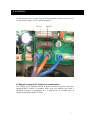
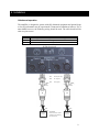
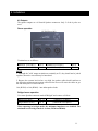
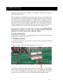
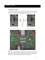
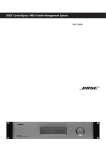
B1500 / B2000 Power Amplifiers
Owner s Guide
Designed for
1. Safety Information
Safety Warning
This unit is fitted with a 3-wire power connector. For safety reasons, the earth lead
should not be disconnected in any circumstance. If ground loops are encountered
consult the section on input connections later in this manual.
Please pay special attention to the AC power considerations part in chapter 4 and
the Maintenance part in chapter 6.
To reduce the risk of fire or electric shock, do not expose the unit to rain or
moisture.
To avoid electrical shock disconnect from the mains supply before removing the
cover. The installation of Bose® Equaliser cards or servicing should be carried
out by qualified personnel only.
Please read this owner s guide
The Model B1500 and B2000 Professional Stereo Power Amplifiers are carefully
engineered to provide excellent sonic performance. This guide will help you set up
and operate your system correctly.
Record your serial number here:
Model B1500 Professional Stereo Power Amplifier: ___________________________
Model B2000 Professional Stereo Power Amplifier: ___________________________
Date of purchase ___________________ Retailer s name ______________________
For ease in obtaining service, we recommend that you keep your purchase receipt, or
a copy of the receipt, in this owner s guide.
2
Contents
1. Safety Information
2. Before you begin
2.1. Unpacking the Amplifier
3. The B1500 and B2000 Professional Power Amplifiers
4. Installation
4.1. Location and general precautions.
4.2. Mechanical considerations
4.3. Thermal considerations
4.4. AC power considerations
4.5. Magnetic leakage and R.F interference considerations
4.6. Inputs
..
4.7. Linking amplifiers.
4.8. Bridged mono operation .
4.9. Outputs
5. Operation.
5.1. Switching on
5.2. Level controls
5.3. Signal indicators
5.4. Limiters
5.5. Temperature control
5.6. Fault indicators
5.7. Bridged LED
6. Faults / Fuses / Maintenance
7. Bose EQ Cards
7.1. B1500 EQ card fitting
.
7.2. B2000 EQ card fitting
7.3. EQ card fitting for bridged mono operation
8. Technical Specification
9. Declaration of Conformity
2
......... 4
.. 5
.
6
6
......... 6
.. 6
7
......... 8
10
...10
.11
.12
.. 12
...12
12
........ 12
.12
12
....13
.14
.14
........... 15
. 16
.. 17
. 18
3
2. Before You Begin
Congratulations on your purchase of a new BOSE® Professional Stereo Power
Amplifier. The product has been designed to provide excellent sonic quality and has
been engineered for reliability.
2.1 Unpacking the amplifier
Carefully unpack your amplifier. Keep the original carton and packing materials for
possible future use. Check for any visible signs of damage. If the amplifier appears
damaged, do not try to use it. Notify the Bose Product Support or your authorised
Bose ProPartner.
4
3. B1500 / B2000 Power Amplifiers
The B1500 or B2000 Amplifier is a no compromise, high quality, class AB power
amplifier.
Fan speed is varied as required to keep the amplifier within its temperature limits.
Signal limiters are included to protect speakers from clipped signals.
The amplifiers include full DC and short circuit protection on the outputs to ensure
trouble-free service in harsher environments.
The B1500 & B2000 amplifiers are a good power match for BOSE mid/high and bass
loudspeaker products, especially in foreground entertainment systems.
The B1500 amplifier is rated at 450 watts per channel 8 ohms and 715 watts per
Channel into 4 ohms and 1025 watts per channel into 2 ohms. In bridged mono
operation, it is rated at 1430 watts into 8 ohms and 2050 watts into 4 ohms.
The B2000 amplifier is rated at 560 watts per channel 8 ohms and 925 watts per
Channel into 4 ohms and 1300 watts per channel into 2 ohms. In bridged mono
operation, it is rated at 1850 watts into 8 ohms and 2600 watts into 4 ohms.
The inputs of each amplifier are high quality, electronically balanced and have high
common-mode rejection for exceptional hum and noise rejection. In addition, both the
B1500 and the B2000 amplifiers are equipped with internal connectors that enable the
use of BOSE Equalisation cards (EQ cards) one for each channel. This allows for
different equalisation for each channel if required (provided the correct equalisation
cards are installed). Equalisation cards are available for the entire range of BOSE
professional loudspeakers that require dedicated product equalisation.
A sample setup might involve one B1500 power amplifier driving two channels of
BOSE 802® III loudspeakers in stereo mode. A second Model B1500 power amplifier
in bridged mono mode could be added to drive a BOSE 502®B bass module.
Alternatively, just one amplifier could be used to drive the BOSE 802® III
loudspeakers on one channel and the BOSE 502®B module on the other channel.
Many configurations are possible. This flexibility can be achieved by installing the
EQ cards for the desired setup.
5
4. Installation
4.1 Location and general precautions
Locate the unit where it will not be exposed to rain or moisture. If fluid or a foreign
object enters the unit, disconnect the power plug. Do not pull by the cord; grasp the
plug firmly. Contact an authorised dealer or service centre.
Locate the unit where it will be protected from heat and allow adequate ventilation.
Place it away from direct heat sources, such as heating vents and radiators. Make sure
the ventilation holes are not covered and air can circulate freely behind, beside, and
above the unit.
4.2 Mechanical considerations
When mounting the amplifier in a rack or enclosure ensure the rear of the unit is
adequately supported. The brackets, which are supplied, fit standard 19-inch (483mm)
rack mounting systems. THE FRONT PANEL IS NOT CAPABLE OF
SUPPORTING THE UNIT ON ITS OWN.
4.3 Thermal considerations
When mounting the amplifier in a rack or enclosure ensure THERE IS ADEQUATE
VENTILATION. The cooling fans suck cool air in through the front and blow hot air
out at the rear of the unit through the ventilating grills. IF THIS AIR IS NOT
ALLOWED TO ESCAPE, OVERHEATING WILL OCCUR. Take care when
mounting other equipment in the same rack.
4.4 AC power considerations
The B1500 and B2000 power amplifiers have been manufactured to comply with
local power supply requirements. Both have been set at a mains voltage of 240Volts.
Be sure to connect your power amplifier to a supply capable of supplying the correct
voltage and adequate current to allow full-power operation of the power amplifier.
The current demand of a power amplifier varies depending on the impedance of the
load, the output level of the power amplifier and content of the program material.
Before connecting the unit to the supply, ensure that the voltage (printed on the rear
panel of the amplifier) is correct and that a mains fuse of the correct type and rating
has been fitted in the fuse holder on the rear panel of the amplifier (The B2000 is
fitted with a circuit breaker and hence does not have a mains fuse on the rear panel).
Mains cabling to both the B1500 and the B2000 should be protected by suitable over
current device.
Note:
To convert the B1500 and B2000 to 220V operation, one should proceed as follows
(see also the following picture):
Locate the violet & brown wires from the mains transformer to the PCB spade
connectors marked up as Live Tx and Spare Tx . Connect the violet wire to Live
6
4. Installation
Tx and the brown wire to Spare Tx for 220Volt operation (Connect brown to Live
Tx and violet to Spare Tx for 240Volt operation ).
Live Tx
Spare Tx
B1500 shown only
.
4.5 Magnetic leakage & R.F Interference considerations
Like all high power amplifiers, B1500 & B2000 should be kept away from other
equipment that is sensitive to magnetic fields. Also, this amplifier may suffer a
substantial reduction in performance if it is subjected to, or mounted close to
equipment that radiates high R.F. fields.
7
4. Installation
4.6 Inputs
The inputs are made via 3-pin XLR connectors, which are electronically balanced and
should be connected via a high grade twin core screened cable, as follows: Balanced operation
Pin No.
1
2
3
Connection
Screen (ground)
Hot (signal +)
Cold (signal -)
B1500 shown only
PIN1 - Screen (see note)
PIN2 - Hot (signal +)
PIN3 - Cold (signal -)
GND
(Shield)
GND
(Shield)
GND
(Shield)
+ +
-
GND
GND
(Shield)
+ +
-
GND
Balanced
Source
Balanced
Source
Channel A
Channel B
NOTE: This amplifier is wired to the latest industry recommendations. PIN1 is
connected directly to the chassis/mains earth. If ground loops (mains hum) are
encountered, remove the screen connection from the other end of the cable and leave
it open circuit. If problems persist, consult your dealer/supplier. DO NOT TAMPER
WITH OR ALTER ANY GROUND (EARTH) CONNECTIONS INSIDE THE
AMPLIFIER.
8
4. Installation
Unbalanced operation
The amplifier is designed to operate with fully balanced equipment and ground loops
or loss of performance may be experienced if connected to unbalanced sources. If it is
unavoidable however, the following wiring should be used. The cable should still be
twin core plus screen.
Pin No.
1
2
3
Connection
Screen (ground) Connect to ground at unbalanced equipment or float
Hot (signal +)
Cold (signal -)
B1500 shown only
PIN1 - Screen (see note)
PIN2 - Hot (signal +)
PIN3 - Cold (signal -)
GND
(Shield)
GND
(Shield)
+ +
+ -
GND
(Shield)
GND
Unbalanced
Source
Channel A
Gnd/Shield
Either connect to source
ground or leave floating
(no connection)
+
GND
(Shield)
GND
Unbalanced
Source
Channel B
9
4. Installation
4.7 Linking amplifiers
Each amplifier channel is provided with a 3-pin XLR connector marked Link which
allows the input signals to be linked to further amplifiers etc. The pin connections are
the same as for the input.
4.8 Bridged mono operation
For bridged mono operation connection should be made to channel A input only. Set
the rear panel bridge switch to the bridged mono position for bridged mono operation.
The output should be taken from the bridged output Speakon connector
When using a B1500 or B2000 in bridged mono with a BOSE® EQ card, only 1 card
should be fitted into the channel A EQ connector socket located inside the amplifier.
For further details see chapter 7: Bose® EQ cards.
10
4. Installation
4.9 Outputs
The speaker outputs are via Neutrik Speakon connectors. Only 2 of the 4 poles are
used.
Stereo operation
B1500 Shown Only
Terminations are as follows:Channel A Live (Hot) +
Pin +1
Channel A Return(Cold) - Pin -1
Channel B Live (Hot) +
Channel B Return(Cold) -
Pin +1
Pin -1
NOTE:
1. Although the "cold" output terminals are nominally at 0V, they should not be joined
together; otherwise cross-talk may be introduced.
2. Because the currents involved are very high, the speaker cables should conform to
the following minimum requirements, otherwise the losses will cause the cables to get
hot and audio power will be reduced:
14A (B1500) or 16A (B2000) - into 4ohm speaker loads
Bridged mono operation
Use centre Speakon connector marked Bridged and connect as follows:
Bridged Live (Hot) +
Bridged Return (Cold) -
Pin +1
Pin -1
(Channel A in phase)
(Channel B out of phase)
When operating in bridged mode, the minimum impedances are doubled. The
minimum load in bridged mode is: 4 ohms (B1500 and B2000).
11
5. Operation
5.1 Switch on
At Switch-on the protection circuit will initially activate whilst the circuits stabilise.
Assuming no faults are detected after a few seconds only the POWER LED (and
SIGNAL indicators if signal is applied) will illuminate.
5.2 Level controls
These are analogue controls allowing precise level settings. Note that in BRIDGED
mode only channel A control is active.
5.3 Signal indicators (blue LED)
These are active from a minimum output level of approximately 1 Watt (B1500) or
10 watts (B2000) and are an indication only of signal presence.
5.4 Limiters (amber LED)
The B1500 & B2000 amplifiers incorporate signal limiters, which are preset to
prevent clipping with high levels of drive. The amber LED's on the front panel
illuminate to indicate operation of the limiters.
5.5 Fault indicator (Audio Protection red LED)
If the outputs are shorted or if DC is present, the protection circuit will disengage the
outputs and the Audio Protection (A/P) LED will illuminate. The amplifier will
continue to be monitored and depending on the type of fault, will either reset after the
fault has been cleared or by switching the mains switch off and then on again after a
few seconds. (See also temperature control above)
Temperature related faults will reset once the unit has cooled sufficiently.
Output short circuits will require manual reset after clearing the fault.
5.6 Bridged (green LED)
This indicates the position of the switch on the rear panel and is illuminated when
bridged mode is selected with the switch pressed in.
5.7 Temperature control
The cooling fans respond to temperature sensors within the unit to maintain a safe
operating temperature. In the event of excessive temperature, the protection circuit
will disable the output. The red Audio-Protect (A/P) LED will indicate this condition
(see fault indicator).
The B1500 has two fans connected permanently with variable speed.
The B2000 has one fan per channel and has a jumper link to enable them from cold.
Normal dynamic signals will not cause the amplifier to overheat unless the
ventilation is inadequate. (See installation section and maintenance section.)
12
6. Faults / Fuses / Maintenance
There are internal secondary (low voltage) fuses on some internal supply rails.
In the event of failure the unit MUST BE DISCONNECTED FROM THE MAINS
SUPPLY BEFORE REMOVING THE UNIT COVER. The fuses should be
replaced with the same type only. THIS SHOULD BE CARRIED OUT BY
QUALIFIED PERSONS ONLY.
WARNING:
If the replaced fuse blows again then there is a serious fault within the unit.
Refer to a service engineer or contact your dealer. NEVER INCREASE THE
RATING OF THE FUSE.
ENSURE THAT ELECTRICAL POWER TO THE UNIT IS DISCONNECTED
BEFORE CARRYING OUT ANY MAINTENANCE.
NOTE:
The filter between the air intake (frontplate) and the frontpanel of the B1500 & B2000
amplifiers should be cleaned or replaced periodically, e.g. 12-24 months. (Filters in
amplifiers located in more 'dirty' atmospheres may require more frequent
maintenance). No special tools are required to remove the filters. The filter should be
'dry' cleaned, using a vacuum cleaner preferably. Running the amplifier without a
filter is not recommended. Replacement filter material is available.
No other regular maintenance is required.
If you have any doubt about carrying out this procedure, refer to a qualified
service engineer or contact your Bose ProPartner.
13
7. BOSE® EQ Cards
The B1500 and B2000 power amplifiers are compatible with the entire range of
BOSE Equalisation Cards.
When configuring a bi-amplified system jumper links allow you to select high pass
filter functionality on certain EQ cards for mid/high loudspeakers. This rolls off the
low frequency to the mid/high loudspeaker providing the low frequency crossover
point to match BOSE bass loudspeakers. An example of this would be BOSE 502®A
Articulated Array on channel A with the HPF link in place and a BOSE 502®B Bass
Module on channel B with no HPF link. Note: When using the BOSE series II-S EQ
cards the HPF selection is made on the EQ card and not on the amplifier board.
In order to fit the EQ Cards you must remove the unit s cover (ENSURE THAT
ELECTRICAL POWER TO THE UNIT IS DISCONNECTED BEFORE
REMOVING THE LID AND FITTING THE EQ CARDS).
For Both B1500 & B2000
Using a TORX T10 screwdriver (not supplied) remove the 12 TORX T10 screws that
retains the cover. Remove the cover.
7.1 B1500 EQ card fitting
Locate the EQ Card sockets. Insert the EQ Card into the socket, noting the orientation
of the mating connector.
Remove the bypass jumper link for the channel, (A = J7 or B = J6)
If you want to activate the high-pass filter function of the EQ Card, you should fit the
jumper that you previously removed from (J7 or J6), to the HPF pins for the channel
(A = J8 or B = J5) linking pins 2 and 3. Note: When using the BOSE series II-S EQ
cards the HPF selection is made on the EQ card and not on the amplifier board.
14
7. BOSE® EQ Cards
7.2 B2000 EQ card fitting
Locate the EQ Card sockets. Insert the EQ Card into the socket, observing the
orientation of the mating connector. Remove the bypass jumper link for the channel
(A = J104 or B = J204) and replace horizontally as shown below:
Front of
Amplifier
Bypass active channel A
EQ card active channel A
Jumper location channel A
Jumper location channel B
Front of
Amplifier
If you want to activate the high-pass filter function of the EQ Card, you need to fit the
jumper (that is supplied within the packaging that comes with the amplifier) to the
link HPF pins for the channel. Note: When using the BOSE series II-S EQ cards the
HPF selection is made on the EQ card and not on the amplifier board.
15
7. BOSE® EQ Cards
7.3 EQ card fitting for bridged mono operation
The Bose EQ card should be fitted into the channel A connector inside the amplifier
and the input signal should be connected to input A. The bridge switch on the rear of
the amplifier should be set to bridge mode. The output is then taken from the bridged
output Speakon socket on the rear of the amplifier.
For Both B1500 & B2000
Re-fit the unit s cover (BEFORE CONNECTING THE ELECTRICAL POWER
TO THE UNIT) using the 12 TORX T10 screws removed earlier.
For further information about BOSE equaliser cards or fitting the equaliser cards into
the B1500 or B2000 power amplifiers please contact your Bose supplier.
16
8. Technical Specification
TECHNICAL SPECIFICATION B1500
POWER OUTPUT:
Continuous output power,
both channels driven:
Power values measured at 230Vac
450 Watts per channel into 8 from
20Hz to 20 kHz, with no more than
0.03% THD
715 Watts per channel into 4 from
20Hz to 20 kHz, with no more than
0.03% THD
1025 Watts per channel into 2 from
20Hz to 20 kHz, with no more than
0.03% THD
Bridged-mono operation:
1430 watts into 8 from 20Hz to 20
kHz, with less than 0.03% THD
2050 watts into 4 from 20Hz to 20
kHz, with less than 0.03% THD
CMRR:
> 90dB
Frequency response:
20Hz to 20 kHz (±0.5dB)
Fusing:
10 Amp Slow-blow
(230V/50Hz)
Input impedance:
20k balanced
Hum & noise
-105dB
Sensitivity:
1.38V rms for rated power into
4 (+5dBu)
Damping factor 1 kHz:
>400 (at 8 )
Gain:
32 dB
Size (H x W x D):
88 mm x 482 mm x 428 mm
THD 4 :
1 kHz <0.008%
20Hz to 20 kHz <0.03%
Net weight:
20 kg
Power requirements:
230VAC/50-60Hz (Europe & UK
Amplifier set at 240Vac)
TECHNICAL SPECIFICATION B2000
230VAC/50-60Hz (Europe & UK
Amplifier set at 240Vac)
POWER OUTPUT:
Continuous output power,
both channels driven:
2600 watts into 4 from 20Hz to 20
kHz, with less than 0.03% THD
Power values measured at 230Vac
Frequency response:
20Hz to 20 kHz (±0.5dB)
560 watts per channel into 8 from
20Hz to 20 kHz, with no more than
0.03% THD
Input impedance:
20k balanced
Fusing:
15 Amp Trip
(230V/50Hz)
Sensitivity:
1.75V rms for rated power into
4 (+7dBu)
Hum & noise
-105dB
925 Watts per channel into 4 from
20Hz to 20 kHz, with no more than
0.03% THD
1300 Watts per channel into 2 from
20Hz to 20 kHz, with no more than
0.03% THD
Bridged-mono operation:
1850 watts into 8 from 20Hz to 20
kHz, with less than 0.03% THD
Gain:
32 dB
THD 4 :
1 kHz <0.008%
20Hz to 20 kHz <0.03%
CMRR:
> 90dB
Damping factor 1 kHz:
>400 (at 8 )
Size (H x W x D):
88 mm x 482 mm x 428 mm
Net weight:
25 kg
Power requirements:
17
9. Declaration of Conformity
DECLARATION OF CONFORMITY
We, the offerer:
Bose Corporation, The Mountain, Framingham, MA 01701-9168 USA
acknowledge our responsibility, that the product:
Kind of equipment: Audio amplifier
Type designation: B1500 Professional Power Amplifier,
B2000 Professional Power Amplifier
in accordance with EMC Directive 89/336/EEC and Article 10(1) of the Directive,
is in compliance with the following norm(s) or document(s):
Technical Regulations: EN 55103-1:1996, EN55103-2:1996
&
in accordance with the Low Voltage Directive 73/23/EEC,
is in compliance with the following norm(s) or document(s):
Technical Regulations: EN/IEC60065:2002 7th Edition
01/07/2006
Bose G.P.
Castleblaney Road Vice President Europe
Carrickmacross
Co Monaghan
Ireland
Nic Merks
Authorized EU representative
How to reach the sales offices in Europe
Austria
Professional Systems Division, Austria
Bose Ges.m.b.H., Business Park Vienna
Wienerbergstrasse 7, 10 O.G.
1100 Wien, Österreich
Telephone: 01-60404340
Fax: 01-604043423
The Netherlands
Professional Systems Division, The Netherlands
Bose B.V., Nijverheidstraat 8
1135 GE Edam, Nederland
Telephone: 0299-390139
Fax: 0299-390109
e-mail: [email protected]
Belgium
Professional Systems Division, Belgium
Bose N.V., Limesweg 2
3700 Tongeren, België
Telephone: 012-390800
Fax: 012-390840
Norway
Professional Systems Division, Norway
Bose Filial till Bose A/S Danmark, Lerkev 58
2209 Kongsvinger, Norge
Telephone: 062-821560
Fax: 062-821569
Denmark
Professional Systems Division, Denmark
Bose Danmark A/S, Industrivej 7
PO Box 14, 2605 Brøndby, Danmark
Telephone: 43437777
Fax: 43437818
Poland
Bose Sp. z o.o.
Galeria Mokotów
ul. Wo oska 12
02-675 Warszawa
Telephone: (22) 852 2928, Fax: (22) 852 2927
e-mail: [email protected]
website: www.bose.pl
France
Professional Systems Division, France
Bose S.A., 12 rue de Témara
78100 Saint Germain en Laye
Telephone: 01-30616363
Fax: 01-30616388
Germany
Professional Systems Division, Germany
Bose GmbH, Max-Planck-Straße 36,
61381 Friedrichsdorf, Deutschland
Telephone: 06172-7104-0
Fax: 06172-7104-19
website: www.bose.de
Ireland
Professional Systems Division, Ireland
Bose GP, Castleblayney Road
Carrickmacross, County Monaghan
Republic Of Ireland
Telephone: 042-9661988,
Fax: 042-9661998
Italy
Professional Systems Division, Italy
Bose SpA, Via della Magliana 876
00148 Roma, Italia
Telephone: 066-5670802, Fax: 066-5680177
e-mail: [email protected]
Switzerland
Professional Systems Division, Switzerland
Bose AG, Hauptstrasse 134
4450 Sissach, Sweiz
Telephone: 061-9757733
Fax: 061-9757744
Spain
Gaplasa S.A.
Avda. Ingeniero Conde de Torroja 25
28022 Madrid, España
Telephone: 91 748 29 60
Fax: 91 329 16 75
e-mail: [email protected]
Sweden
Professional Systems Division, Sweden
Bose, filial till Bose A/S Danmark
Johannefredsgatan 4, 43153 Mölndal, Sverige
Telephone: 031-878850
Fax: 031-274891
United Kingdom
Professional Systems Division, United Kingdom
Bose Ltd., 1 Ambley Green
Gillingham Business Park
Gillingham, Kent ME8 0NJ, England
Telephone: 0870-741-4500, Fax: 0870-741-4545
e-mail: [email protected]
website: www.bose.co.uk