1
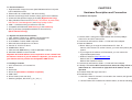
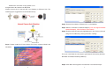
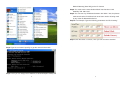
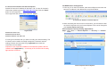
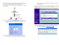
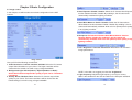
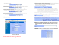
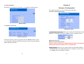
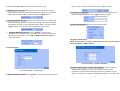
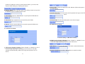
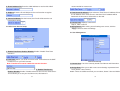
Camera IP LAN - Wireless - USB
BOSSC55
User’s Manual
The information in this document is subject to change without notice.
This document contains materials protected by copyright. All rights are
reserved. No part of this manual may be reproduced or transmitted in any
form, by any means or for purpose without express written consent.
Federal Communications Radio Frequency Interference Statement.
Note: This equipment has been tested and found to comply with the limits
for a Class B digital device, Pursuant to part 15 of the FCC Rules. These
limits are designed to provide reasonable protection against harmful
interference when the equipment is operated in a residential installation.
This equipment generates, uses and can radiate radio frequency energy
and if not installed and used in accordance with the instruction manual may
cause harmful interference to radio communications. However, there is no
guarantee that interference will not occur in a particular installation. If this
equipment does cause harmful interference to radio of television reception,
which can be determined by turning the equipment off or on, the user is
encouraged to try to correct the interference by one or more of the following
measures:
z Reorient or relocate the receiving antenna.
z Increase the separation between the equipment and receiver.
z Connect the equipment into an outlet on a circuit different from that to
which the receiver is connected.
z Consult the dealer or an experienced radio TV technician for help.
Notice :
(1) The changes or modifications not expressly approved by the party
responsible for compliance could void the user authority to operate the
equipment.
(2) Shielded interface cables and AC power adapter, if any must be used in
order to comply with the emission limits.
0
CE DECLARATION
This device complies with CE class B.
*EN55024
EN61000-4-5
EN55022
EN61000-4-2
EN61000-4-6
EN61000-3-2
EN61000-4-3
EN61000-4-8
EN61000-3-3
EN61000-4-4
EN61000-4-11
Printed in Taiwan R.O.C.
All contents are subject to change without notice.
1
All trademarks are the property of their respective owner.
Table of the contents
Chapter 1 Welcome to Wi-Fi Camera Pro/IP Camera Pro
1.1 Introduction
1.2 Product Features
1.3 System and network environment
1.4 Package Contents
Chapter 2 Hardware Description and Connection
2.1 Hardware description
2.2 Quick Start: IP Camera Auto Detection
2.3 Access the IP Camera via Internet Explorer
2.4 WEB Browser Configuration
2.5 IP Address Configuration
2.6 Administrator Configuration
2.7 How to Connect to Internet with ADSL
2.8 WEB Camera (USB Camera) Configuration
2.9 Use the virtual IP to connect with Internet
Chapter 3 Basic Configuration
3.1 Image control
3.2 Basic LAN configuration
3.3 Wireless Setup
3.4 Network Status
3.5 System / Client Log
Chapter 4 Advance Configuration
4.1 Device administrator Setup
4.2 PPPoE Setup
4.3 Dynamic DNS Setup
4.4 FTP Service Setup
4.5 E-Mail Service Setup
4.6 NTP Timer Service Setup
4.7 User Management
Chapter 5 TROUBLESHOOTING
Issue:08/30/2006
Version: A
P/N: 34408000
2
CHAPTER 1
3
3
4
4
4
5
5
6
10
11
13
14
15
16
20
22
22
25
26
28
28
29
29
30
31
32
33
34
35
37
Welcome to Wi-Fi Camera Pro/IP Camera Pro
1.1 Introduction
Today, more people are aware of their personal, home and office security
and are finding solutions to protect themselves. Our Wi-Fi Camera Pro
provides the ideal solution by operating easily with your Internet Explorer
web browser.
Wi-Fi Camera Pro has a built-in high-speed image and network processor,
providing you with a powerful embedded device with many Internet services
such as Email, FTP, DDNS, PPPoE, NTP, User Manager, and Image
Control. The Wi-Fi Camera Pro includes a high quality CMOS sensor with
6 infrared LEDs that provide excellent imaging in dark and low light
situations.
3
1.2 Product Features
1. High Resolution Image Processor (640*480/320x240/176*144) with
built-in MJPEG encoder.
2. Ethernet RJ-45,10/100 Base-T with auto-sensing.
3. Remote view through the IE browser, simply type in the IP address.
4. 6 infrared LEDs provide imaging in the dark.(Night Version only)
5. Many Valuable Internet services: Email, FTP, PPPoE, Dynamic DNS,
NTP service, User Management, and Image quality Control.
6. USB 1.1 Interface making it useful as a web cam.
7. Compatible with Microsoft MSN Messenger and NetMeeting.
8. 802.11g wireless (Compatible with 802.11b Access Point)
(Wi-Fi Camera Pro only).
1.3 System and network environment
1. LAN: 10Base-T Ethernet or 100Base TX Fast Ethernet.
2. More than one fixed IP address is recommended.
3. A 10/100Base-T switch HUB is required.
4. Microsoft Internet Explorer 5.0 or above.
5. Pentium III 1G CPU or above.
6. 64MB RAM or above.
7. VGA card with 8MB Memory or above (800x600 or above).
8. Windows 2000/XP is recommended.
Important: A fixed IP address is not required to access camera from
the Internet. However if your IP address is dynamic, you need to ask
your Internet service provider for the Dynamic DNS service.
1.4 Package Contents
1. Wi-Fi Camera Pro or IP camera Pro
2. Mount
3. Quick start
4. Driver CD (Surveillance software is optional)
5. USB Cable
6. RJ-45 Cable (cross over wire)
7. Switching Adapter, DC 5V/2A (-) Å ( ƔÆ (+)
4
CHAPTER 2
Hardware Description and Connection
2.1 Hardware description
1. Camera switch: Change the mode between PC Camera (USB),IP
Camera Pro and Wi-Fi Camera Pro
2. Connections and Interface: USB 1.1, RJ45 and Power adapter
3. Reset and Default:
a. Reset: When you change the mode between PC Cam, IP
Camera ,Wi-Fi Camera or set the Camera, you must reset (reboot) the
system.
b. If you forget the IP address or ID Password, you can restore the
original default parameters.
c. Default IP address: http://192.168.1.100.
Default User ID: root ,
Default User Password: admin
4. Connections and Interface: USB 1.1, RJ45 and Power adapter
5. A Ready LED: In IP or Wi-Fi Camera mode, when the ready LED is on
(takes about 30 ~ 40 seconds to light) then the IP Camera can be
operated.
5: 6 infrared LEDs with night-vision lens
6.The indicator LED:
a. Link LED : When IP Camera is connected to the network, this light will
be turned on
b. 10/100 T Base LED: Indicates the network status, as well as indicating
5
whether the connection is high speed or not.
2.2 Quick Start: IP Camera Auto Detection
Please connect the IP Camera with your Gateway or Ethernet Hub. The
following figure suggests the recommended set-up:
Step2: Execute the software “IPDetect.exe” on the Desktop
Step3: Select a LAN Device :Network Adapter (It can not support wireless
Network Adapter), Click the button “Auto Detect”
Step4: Find the Internet Camera by highlighting it in the “IPCam List” and
assign the IP address by clicking the button “Setting”
Step1: Please Install the IP Auto Detect Tool (Only supports WinXP and
Win2000).
Then you must follow the next steps to get Network information (Sub Net,
Net Mask and Default Gateway Address):
Step5: Click Start->All Programs->Accessories->Command Prompt
6
7
Default Gateway (Gate Way) to the IP Camera
Step8: You must use the same Subnet Mask” 255.255.255.0 “and
GateWay”192.168.2.254”
Step9: You can use any IP Address between 192.168.2.1-254, but please
make sure that the IP Address has never been used or is being used
by any other IP addressable device.
Step10: For Example: Type the following parameters and click “setting”
Step11 Click the button “Connect”, then you can connect to Camera
Step6 Type the command “ipconfig” to get the network information
Step7: Then you can assign the IP Address, Subnet Mask(NET Mask) and
8
9
2.3 Access the IP Camera via Internet Explorer
Default IP Camera’s IP address is 192.168.1.100. To open IP Camera’s
Home page, please type the http://192.168.1.100 then click the ”Enter”
button on your keyboard.
Then Login with User name: root, Password: admin.
2.4 WEB Browser Configuration
1. From any PC on the local network, start Internet Explorer and enter the
camera’s IP address in the address bar, as pictured below:
IP Camera’s IP Address in Internet Explorer
Login Screen
Default User Name: root
2. When accessing the web server for the first time, you will need to install
an ActiveX component for your Internet Explorer. This can be changed in
your Internet Explorer Security.
Internet Explorer Security Setting: (Appendix B)
Step1 : Click “Tool” => “Internet Options” => “Security” => “Custom
Level”.
Default Password: admin
Default IP address: 192.168.1.100
If it can’t get connected, then you have to modify your network setting. The
IP Camera can be used to manually configure the camera’s network
settings. Please use command “Ping” (Appendix A) to check the
connection for more detail.
Important: If you forget the IP address or ID Password, please click the
“Default” button(Appendix D) on the body of IP Camera until the ready
light has been turned off.
Internet Explorer Internet Options
10
11
3. Please remember these two features must be active “Download
unsigned ActiveX controls” and “Initialize and script controls not
marked as safe” If you want to learn more, please refer to the
troubleshooting section In Chapter 5 : Frequency Ask Questions.
4. Snapshot E-mail: Send the Live Video Screen capture via E-mail, please
refer to the settings about [Configuration] => [Advanced Configuration]
=> [E-mail service Setup].
2.5 IP Address Configuration:
Internet Explorer Security Modify
Step2 : Then, please click “Custom Level” and set the parameters as
follows:
Please click Basic Setup to Link to the Page:
http://192.168.1.100/Eng/BasicSetup.htm
Depending on your network setup, you should see the
following figures:
If there is a fixed IP Address: please set the following
parameters (including Subnet Mask, Gateway IP
Address, Domain Name Service), about the detail, you
can ask for more information from your
Broadband/Cable Internet Service Provider.
ActiveX Security Settings
12
13
2.6 Administrator Configuration
Click Device Admin to Link to the Page:
http://192.168.1.100/Eng/Admin.htm
Important: We use the same default Password with each IP Camera, so
we suggest that you change the password.
Important: Each IP Camera has his own unique Mac Address, so we
suggest you do not change the item ”MAC Address”.
2.7 How to Connect to Internet with ADSL
If you want to connect the IP Camera with Internet and Ethernet at the
same time, you must use the function “ADSL PPPoE”
Step1 : Link to this page: http://192.168.1.100/Eng/BasicSetup.htm, and
select “Get an IP Address by PPPoE”
Step2 : Link to http://192.168.1.100/Eng/PPPoE.htm check the enable
feature and type the ID and Password for your ADSL modem
14
15
Step2 : Please click “Next” to install the USB driver
2.8 WEB Camera (USB Camera) Configuration
Step1 : Install the USB driver on the software CD and click ”SETUP.EXE”
Step3 : Change the switch on the camera to the mode ”Web Camera” and
reset the camera.
Step4 : Connect the IP Camera directly to the computer with USB cable
included. Then click the option “Install the software automatically
(Recommended)”
Setp5 : Select “No, not this time”and click “Next”.
16
17
Step9 : Open Microsoft NetMeeting(c:\program Files\NetMeeting) or MSN
Messenger, then you can control the Image with MSN Messenger
or NetMeeting.
Setp6 : Select “install the software automatically [Recommended]”and
click “Next”.
Setp7 : Click “Continue Anyway”
Step8 : Then you can see the following message:
18
19
2.9: How to use the virtual IP to connect IP Camera and Internet.
If your network Architecture supports the following figure,
You will need to do port and local virtual IP forwarding in the firewall or
gateway setup
following figure is just a example, you need to ask your Internet
Service Provider
Step1 : In this Page “Device administrator Setup”, please enable the
function “Multiport Defaults” and assign a port number for the
IP Cam
Step3 : In the Remote Computer, please open the Internet Explorer,
and input the IP address: http://61.30.13.40:8888
Step2 : Setup your firewall or gateway, and assign a Local Virtual
IP:192.168.1.100 and open a port 8888 for the IP Cam, the
20
21
Chapter 3 Basic Configuration
3.1 Image control
In this chapter, we will introduce some basic configuration for the WiFi
Camera.
4. Auto Exposure: Enable / Disable: Switch the IP Camera Auto Exposure
function between Enable / Disable. By enabling it, the IP Camera will
automatically modulate the lighting conditions.
5. Auto White Balance: Enable / Disable: Switch the IP Camera Auto
White Balance function between Enable / Disable. By enabling it, the IP
Camera will automatically modulate white color for optimal picture quality
in any lighting condition.
6. Sharpness: Switch the IP Camera Auto White Balance function
between Enable / Disable. By enabling it, the IP Camera will
automatically modulate white color for optimal picture quality in any
lighting condition.
7. Hue / Brightness / Contrast / Saturation: Modulate the IP Camera’s
Image performance.
Image Control
Here you’ll find the following control items:
1. Video Resolution: 176*144 / 320*240 / 640*480: Select the IP Camera
output Video Resolution of your choice. The higher resolution will be
clearer than the smaller, but it will occupy a larger bandwidth.
2. Background Light: Normal(indoor) / Special(Outdoor or Dark):
Select the IP Camera output Video quality of your choice. The better
resolutions
3. Quality: Worst / Medium / Best: Select the IP Camera output Video
quality of your choice. The better resolutions will be clearer than the
lowest settings, but it will occupy a larger bandwidth.
22
NOTE: In the dark, we suggest you raise the “brightness”.
7. Light Frequency: Adjust the light frequency to suit your country.
60Hz is the standard for the USA and 50Hz is the European standard.
23
8. Mirror: Adjust the light frequency to suit your country.
60Hz is the standard for the USA and 50Hz is the European
standard.
3.2 Basic LAN configuration
9. Rotate: Adjust the light frequency to suit your country.
60Hz is the standard for the USA and 50Hz is the European
standard.
NOTE: After adjusting these parameters, please click the ”Apply” button to
save your new settings. If you don’t want to keep the new settings, click the
“Undo” button to give up those modifications.
IP Camera Setting – Basic LAN Setup
1. Host Name & Domain Name: If you do not know this one, you can
ignore this item
2. MAC Address: Shows the current MAC address used by the IP Camera.
3. Get an IP address by PPPoE: If “Get an IP Address by PPPoE” is
selected, you must setup the PPPoE configuration. (In order to login to
the ADSL Modem).
4. Get an IP address by DHCP: If your Network is defined with DHCP
assigning the IP address. Then you won’t need to assign the IP address
by yourself manually.
5. Specify an IP address: Please specify your IP Camera II’s IP address
by manually assigning one yourself. Don’t assign the same IP address as
24
25
other Network devices.
1. Wireless opmode: Ad Hoc / Infrastructure: Switch the Wi-Fi Camera
wireless mode between the Ad Hoc mode (point to point), or
Infrastructure mode (Broadcast).
6. Subnet Mask Address: Default Subnet Mask Address is: 255.255.255.0
8~10. Domain Name Server: Your Internet Service provider will provide
you with at least one DNS IP Address.
Ad Hoc : If you want to connect the Wi-Fi camera and PC or notebook
directly, please select this mode. But you must make sure your
notebook includes the Wireless LAN Card (802.11b/g) and you
must set the parameter for 802.11b/g and Ad Hoc.
Infrastructure: If there is a wireless AP ( Access Point), please select this
mode.
2. SSID: SSID works best with the User ID which is used by the WLAN.
3.3 Wireless Setup
3. Encryption Type : Switch Encryption Type.
7. Default Gateway IP Address: Depends on your Internet Service
Provider. Please contact them for further assistance.
6. Key: Assign WEP digital Number Key. The digital numbers must the
same as the WEP Key which was used by the Wireless AP (Access
Point).
7. IP setup: you can use the same parameter, prefers the Basic Setup
Wireless LAN Setup
Note:This function only used by Wi-Fi Camera Pro.
26
27
3.4 Network Status
Chapter 4
Shows the current Ethernet information, we suggest the following figure:
Advance Configuration
This chapter introduces you to the advanced configuration.
4.1 Device administrator Setup
Network Status
3.5 System / Client Log
Administrator Setup
1. Administrator Password: Allows you to modify the Administrator’s login
password. Remember to click the “Apply” button to update and save.
System / Client Log
Shows the System / Client Logs, please click the “Reload” button to load
the newest logs. Displays the details of the [Client Login Time] [IP address]
[MAC Address] information.
Default User ID: root
Default User Password: admin
Caution: Please remember your Administrator password. If forget your
administrator password, please refer to chapter5 Q/A.
4. MAC Address: Allows you to modify the WiFi Camera’s MAC address.
Please input the unique MAC address.(refer to Chapter 2.6). Then click
the “Apply” button to update the setting.
28
29
Please use the MAC address which was printed in the case.
5. Reset Device: Yes / No: Allows you to reset your Wi-Fi Camera and
restart without losing any stored information and settings. To enable this
feature, please select “Yes”, and then click the ”Apply” button.
6. Factory Defaults: Yes / No: Allows you to reset your Wi-Fi Camera and
restart with factory default information and settings. All stored information
and settings will clear. To enable, please select “Yes”, and then click the
“Apply” button. It is the same with the Hardware factory reset.
Then you can connect the IP Camera with an ADSL modem.
2. User Name / Password: Input PPPoE User Name and Password for
automatic login PPPoE then click “Apply” button to update.
3. PPPoE Management: Shows current PPPoE status.
3. Multiport Defaults: Yes / No: Check “Enable” to allow you to
configure the broadband router from WAN side. To access the setting
page from external side, enter ”http://<WAN IP Address>: 8080” in
the web browser
4.3 Dynamic DNS Setup
NOTE: You will have to contact your Internet Service Provider (ISP) to
activate a Dynamic DNS program.
4.2 PPPoE Setup
IP Camera Setting – Dynamic DNS Setup
IP Camera Setting – PPPoE Setup
1. PPPoE: Enable / Disable: Click “Enable” to enable the PPPoE function.
30
1. Dynamic DNS: Enable / Disable (Not Update): Select “Enable” or
“Disable (Not Update)” to use or not to use the Dynamic DNS
mechanism. The ISP will dynamically allocate an IP address to your
router, if you dial up to Internet by ADSL/Cable modem. If you want the
31
dynamic IP address to map to a static Domain Name, you can set the
Dynamic DNS Settings by enabling this feature.
2. Server URL: Define the upload FTP URL address. (Without the path of
the FTP server)
2. Domain Name: Input a domain name in this field you want to map to the
IP address of your broadband/cable router.
3. User & Password: The user name and the password to login to the FTP
server.
3. User Name: Input the “Web Address” of your Dynamic DNS Service
4. Password: Input a password to access the dynamic DNS.
4. Remote Path: The file and folder path to store those images.
5. Server: Input the server address to access the dynamic DNS server.
4.5 E-Mail Service Setup
4.4 FTP Service Setup
IP Camera Setting – E-Mail Service Setup
1. E-Mail service: Enable / Disable: Select “Enable” or “Disable” to use
or not use image capturing to be sent via E-mail service.
IP Camera Setting – FTP Service Setup
2. Mail Server: Input your mail server to send this e-mail (POP3 Server)
1. FTP service: Enable / Disable: Select “Enable” or “Disable” to use or
not use image capturing for uploading to an FTP server. The WiFi
Camera will automatically capture the image and upload to an FTP
Server
32
3. Sender’s Address: Input the e-Mail address to send this e-Mail.
33
4. E-mail address To: Enter the e-Mail address to receive this e-Mail.
5. Subject: Enter the E-mail Subject for the mail receiver recognize.
recommended for Internet use.
4. Time Server IP address: Input reference Time Server IP address. Enter
the IP Address of the Time Server in this field. The IP address will be
listed with the time server information on the web.
6. Interval In Minute: Set the interval, the E-mail will be sent the set
interval time period.
5. Current time: Displays current time.
Sep 01, 2004 13:30:42
6. Apply/Cancel: After making sure all settings are correct, click the
“Apply” button to store the settings.
4.6 NTP Timer Service Setup
4.7 User Management
IP Camera Setting – NTP Time Service Setup
1. Enable Time Zone: Enable / Disable: Enable / Disable Time Zone
reference
2.Time Zone: Select your local Time Zone area. It will reference the GMT
location time for your WiFi Camera.
Note: Time Server must be enabled to use this function.
3. Enable Time Server:
Enable / Disable: Enable / Disable reference time from the Time Server.
This is allows you to set your local time zone, this feature is
34
User Account Setup
1. Current User: List of the currently stored User Names and information.
2. Assign User: Allos you to add a new user and assign a password and
Level (Guest / User / Admin).
Level : There are 3 different levels you can select, Guest / User and Admin.
35
CHAPTER 5
TROUBLESHOOTING
Please check the following chart for a possible solution to a problem. If you
are experiencing a problem, a minor adjustment may eliminate the problem.
Frequently Asked Questions
3. Delete User: Deletes a previously added User account.
IP Camera Installation
Q: What username and password can I use the first time accessing the
IP Camera or after a factory default reset?
A: default User Name = root (all lowercase)
default password = admin (all lowercase)
default IP Address 192.168.1.100
4. Reload: Reloads the list of current registered users.
Q: What should I do if I forget my username and password?
A: Restore the factory default settings by pressing the DEFAULT button
until the ready LED is turned off.
default User Name = root (all lowercase)
default password = admin (all lowercase)
default IP Address 192.168.1.100
Q: Can the IP Camera also work behind the firewall?
A: Yes, you’ll need to do perform port and local virtual IP forwarding in the
setup settings of the firewall. Please refer to your firewall’s user manual or
help files.
36
37
Q: I cannot access the IP Camera from a web browser.
A1: Please use the run command “Ping” (Appendix A) to check the
connection, if the response shown is “Request timed out”, it may be caused
by the setting of the IP Address. Please refer to chapter 2.2.
A2: Check the Ethernet LED of the IP camera. It should blink green and
orange lights. If not, check that both ends of the Ethernet cable are securely
and properly attached..
A3: Our RJ-45 Cable is a cross over wire. Meaning this cable only can be
connected with a switch Hub or connected with the IP Camera being
directly connected to the computer. If you want to connect with an older
Hub, please remember to use a standard RJ-45 Cable.
A4: Confirm that the virtual/local IP address or port [which was used by the
camera (default = 80)] has been forwarded to the camera. Please refer to
your gateway / router’s user manual.
Q: Internet Explorer displays the following message: “Your current
security settings prohibit downloading ActiveX controls”.
A1: Restore the default IE security settings (Medium) or configure the
individual settings to allow downloading and scripts of signed ActiveX
controls. Refer to Appendix B: Internet Explorer Security Settings for
more details.
Q: There are no images available through the web browser?
A1: The ActiveX may be disabled. Please make sure ActiveX has been
enabled in the Internet Options menu. Please see Appendix B: Internet
Explorer Security Settings to correctly configure your Internet Explorer.
Appendix A: Check the Network Connection
Microsoft Windows includes various network information utilities to
determine various network configurations. To determine your IP address
and network settings, please follow the procedures.
1. Click on ”Start” => ”Run” and type in: cmd and then press ”ENTER”
2. Type command: ipconfig and then press ”ENTER”.
3. This will display your network card’s IP address, Subnet Mask, and
Default Gateway. Please remember it, we will use it later.
4. Use the command “Ping” to get the status of the network connection, the
default IP is 192.168.1.100. Please type in the same command windows:
ping XXX.XXX.XXX.XXX. The XXX.XXX.XXX.XXX is your IP Camera’s
IP address. For example: ping 192.168.1.100.
5. If you can see the following report, the connection is successful.
Pinging 192.168.1.100 with 32 bytes of data:
Reply from 192.168.1.100: bytes=32 time<1ms TTL=128
Reply from 192.168.1.100: bytes=32 time<1ms TTL=128
Reply from 192.168.1.100: bytes=32 time<1ms TTL=128
Ping statistics for 192.168.1.100:
Packets: Sent = 4, Received =4, Lost = 0 (0% loss),
Approximate round trip times in mini-second:
Minimum = 0ms, Maximum = 0ms, Average = 0ms
6. If there is no response on this address you’ll see
Pinging 192.168.1.100 with 32 bytes of data:
Request timed out.
Request timed out.
Request timed out.
Ping statistics for 192.168.1.100:
Packets: Sent = 4, Received =0, Lost = 4 (100% loss),
This indicates that the connection is not successful
38
39
Appendix B: Internet Explorer Security Settings
The IP Camera’s web environment Communications using both JavaScript
and ActiveX control technologies. The ActiveX control must be downloaded
from the camera and installed on your PC. There are four things that your
Internet Explorer security settings must allow for the web page to work
correctly.
1.
2.
3.
4.
Download signed ActiveX controls
Run ActiveX control and Plug-ins
Script ActiveX controls marked safe for scripting
Active Scripting (Java Scripts)
All these things are enabled by the default Internet Explorer Security
settings. You can restore the default settings in Internet Explorer by
clicking ”Tool” => ”Internet Options” => ”Security” => ”Default Level”.
Internet Explorer Security Modify
You can also click ”Custom Level” and set the parameter for the following
settings:
ActiveX Security Settings
Internet Explorer Internet Options
40
41
Appendix C: Internet Explorer display error
message or crashes sometime
1. Please remove the Microsoft MSN Tool or MSN Tool Bar
2. Click start->control panel->Add or Remove Programs
Appendix D: Step by step to restore the default
Step by step to restore the default parameter(Wi-Fi Camera and IPCamera3)
Step1: Reboot the Wi-Fi Camera and wait that the indicate Ready LEDs been
turned on
Step2: Even the LED had been turned on, you also need to wait 20 seconds.
Step3: After 20 seconds, you can start to push the Default bottom until the
“READY” LED been turned off
3. Remove the MSN Tool Bar
Default IP address: 192.168.1.100
Default User Name: root
Default Password: admin
42
43
When you need RMA or advanced technical service, please fill in this form
as detailed as possible and FAX or Email it to your dealer or service
representative.
Product S/N:
Name:
TEL No.:
FAX No.:
E-mail address:
Full Address:
Other add-on cards:
Problem description:
44