1
&37
3&WR9LGHR2YHUOD\
23(5$7,210$18$/
DISCLAIMERS
The information in this manual has been carefully checked and
is believed to be accurate. Cypress Technology assumes no
responsibility for any infringements of patents or other rights of third
parties which may result from its use.
Cypress Technology assumes no responsibility for any inaccuracies
that may be contained in this document. Cypress also makes no
commitment to update or to keep current the information contained
in this document.
Cypress Technology reserves the right to make improvements to this
document and/or product at any time and without notice.
COPYRIGHT NOTICE
No part of this document may be reproduced, transmitted,
transcribed, stored in a retrieval system, or any of its part translated
electronic, mechanical, magnetic, optical, chemical, manual, or
Cypress Technology.
© Copyright 2012 by Cypress Technology.
All Rights Reserved.
Version VR1.0 April 2012
TRADEMARK ACKNOWLEDGMENTS
All products or service names mentioned in this document may be
trademarks of the companies with which they are associated.
SAFETY PRECAUTIONS
Please read all instructions before attempting to unpack, install or
operate this equipment and before connecting the power supply.
Please keep the following in mind as you unpack and install this
equipment:
electrical shock and injury to persons.
!
moisture or install this product near water.
Never spill liquid of any kind on or into this product.
Never push an object of any kind into this product through any
openings or empty slots in the unit, as you may damage parts
inside the unit.
Do not attach the power supply cabling to building surfaces.
Use only the supplied power supply unit (PSU). Do not use the PSU
if it is damaged.
Do not allow anything to rest on the power cabling or allow any
weight to be placed upon it or any person walk on it.
To protect the unit from overheating, do not block any vents or
openings in the unit housing that provide ventilation and allow for
"
REVISION HISTORY
VERSION NO.
DATE DD/MM/YY SUMMARY OF CHANGE
VR0
05/02/13
Preliminary Release
VR1
22/04/13
Package Accessories
VR2
02/07/13
Remote Control's PC Key Function
CONTENTS
1. Introduction ............................................ 1
2. Applications ........................................... 1
3. Package Contents ................................ 1
4. System Requirements ............................ 1
5. Features .................................................. 2
6.1 Front Panel ........................................3
6.2 Rear Panel.........................................4
6.3 Remote Control ................................5
6.4 RS-232 Protocols ...............................6
6.5 RS-232 Commands ...........................6
7. OSD Menu and Function List ............... 11
...................................... 13
9. Connection and Installation ............... 14
10. Acronyms .......................................... 15
1. INTRODUCTION
The PC to Video overlay system is designed to overlay PC/
Graphics signal onto Video signal or vise versa. Moreover, it can
convert a variety of VGA sources to Video signal. It is idea for using
in applications like video conference, home theater, business
presentation and lecturing room.
2. APPLICATIONS
Video Conference
Home theater
Business presentation
Lecturing room
3. PACKAGE CONTENTS
PC to Video overlay system
5V DC power supply adaptor
Operation Manual
3.5mm to D-Sub 9 pin Adaptor
D-Sub 15 pin male to D-Sub 15 pin male cable
S-Video cable
Video cable
Remote Control (CR-116 with Battery)
4. SYSTEM REQUIREMENTS
Source equipments such as PC/Video /DVD player with VGA/
Video/S-Video output connector(s)
Displays TV/monitor with VGA/Video/S-Video input connector(s)
1
5. FEATURES
#$%
"&
superimpose Video signal onto VGA source.
Supports VGA to Video conversion
*+8;<=<>=>==;==?=@<E;>?@>=?=@<?;==?@==
Video: NTSC, NTSC4.43, PAL, PAL-M, PAL-N or SECAM
Supports PC & Video picture adjustment
Supports Key adjust and PC aspect
Supports Zoom and Pan functions
#*W!&XY
[;W!>[W!
Cross-platform compatibility for PC, Macintosh and Notebook
Plug-and-Play design, no software driver required
Simultaneously design, no software driver required
Can be adjust from front panel, RS-232 or remote control
Note:
1. The system did not support video format conversion. For example:
NTSC in to NTSC out, PAL in to PAL out or SECAM in to SECAM out.
2. In Overlay mode, suggest the users to preserve the Contrast/
Brightness/Color/Hue in default value.
3. The PC to Video or Video to PC overlay system is designed to
overlay PC/Graphics onto Video signal or vise versa. Simply select
4. Zoom and Pan functions are not supported with Video signal
input is used.
2
6. OPERATION CONTROLS AND FUNCTIONS
The following sections describe the hardware components of the unit.
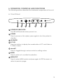
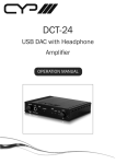
6.1 Front Panel
MENU/EXIT
POWER
1
2
PC KEY
3
4
5
ENTER
6
7
1 POWER LED INDICATOR
The LED will illuminate when power is on.
2 POWER
Press to power on the system, press again to turn the system to
standby.
3 IR SENSOR
4 PC KEY
Press the button to display the combination of PC and Video or
S-Videio screen.
5 Press to toggle through various control or setting values.
6 ENTER
$"
7 MENU/EXIT
Press to enter MENU mode and press again to EXIT the menu or
return to previous page.
3
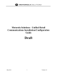
6.2 Rear Panel
PC IN
INPUT
PC OUT
RS-232
S IN
V IN
S IN
OUTPUT
V OUT
S OUT
DC 5V
6
7
V IN
1
2
3
4
5
1 RS-232
Connect 3.5mm phone jack to D-Sub 9pin adaptor to the PC/
Notebook device for RS-232 control.
2 PC INPUT
Connect the input source equipment such as PC/NB for PC signal
input.
3 PC OUTPUT (PASS THROUGH)
Connect the display TV/monitor for PC signal output.
4 V-IN AND S-IN
Switch between Video or S-Video input.
5 VIDEO/S-VIDEO INPUT
Connect the Video/S-Video input port to the source equipment
]*]^^"
6 VIDEO/S-VIDEO OUTPUT
Connect the Video/S-Video output port to the display.
7 DC 5V
Plug the 5V DC power supply into the splitter and connect the
adaptor to AC wall outlet.
4
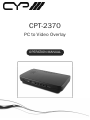
6.3 Remote Control
1 OSD
Press to turn ON/OFF the OSD
on the display.
2 POWER
4
Press to power ON or to
Standby for the system.
3 V IN
Press to select Video input
source. Depending on the S/
V IN switch the output display
will show S/V video.
1
3
6
7
V IN
PC IN
PC KEY
1
2
3
4
5
6
7
8
9
2
5
MENU/EXIT
ZOOM
9
11
POWER
OSD
10
OK
RESET
8
RESET
11
4 PC IN
Press to select PC input source.
5 PC KEY
Press the button to display the
combination of PC and Video
or S-Video screen.
CR-116
6 1~9
When in PC mode, press each key to Zoom the picture to the
"
7 ZOOM
$&`X&xxz&&{*
source.
8 MENU/EXIT
Press to enter MENU mode and press again to EXIT the menu or
return to previously page.
9 a. Press each key to pan the PC picture to different position follow
"
b. To enter the Sub-menu.
10 OK
$&|"
11 RESET
Press once to reset current setting values back to factory default
value.
5
6.4 RS-232 Protocols
Video Scaler
Remote Controller
PIN
]
PIN
]
1
NC
1
NC
2
TXD
2
RXD
3
RXD
3
TXD
4
NC
4
NC
5
GND
5
GND
6
NC
6
NC
7
NC
7
NC
>
NC
>
NC
9
NC
9
NC
Baud Rate: 9600bps
]8>
Parity: None
Stop Bit: 1
Flow Control: None
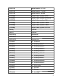
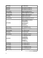
6.5 RS-232 Commands
Command
Description
[POWER1]
power on(normal)
[POWER0]
[KEY0]
Chroma Key--Blue
[KEY1]
Chroma Key--Green
[KEY2]
Chroma Key--Red
[KEY3]
Chroma Key--Black
[OUTPUT0]
output mode--PC
[OUTPUT1]
output mode--VIDEO
6
[OUTPUT2]
output mode--PC KEY
[OUTPUT3]
output mode--CV KEY
[OUTPUT4]
output mode--MIXER
[SYSTEM0]
output video system :NTSC
[SYSTEM1]
output video system :NTSC4.43
[SYSTEM2]
output video system :PAL
[SYSTEM3]
output video system :PALM
[SYSTEM4]
output video system :PALN
[SYSTEM5]
output video system :SECAM
[OSD0]
!
[OSD1]
OSD on
[DISPLAY0]
!
[DISPLAY1]
Display on
[DISPLAY2]
!
[ZOOM0]
"#$
[ZOOM1]
PC ZOOM position 1
[ZOOM2]
PC ZOOM position 2
[ZOOM3]
PC ZOOM position 3
[ZOOM4]
PC ZOOM position 4
[ZOOM5]
PC ZOOM position 5
[ZOOM6]
PC ZOOM position 6
[ZOOM7]
PC ZOOM position 7
[ZOOM8]
PC ZOOM position 8
[ZOOM9]
PC ZOOM position 9
[ZOOMC]
PC PAN center
[ZOOML]
"%&
[ZOOMU]
PC PAN up
[ZOOMR]
PC PAN right
7
[ZOOMD]
PC PAN down
[PANEL0]
Front panel lockout on
[PANEL1]
'*+
[CVCONTx]
video Contrast x=0~63
[CVBRIGHTx]
video Brightness x=0~63
[CVCOLORx]
video Color x=0~63
[CVHUEx]
video Tint x=0~63
[CVDETAILx]
video Sharpness x=0~63
[CVRESET]
Video Adjustment Reset
[CVCONT58]
[CVBRIGHT31]
[CVCOLOR31]
[CVHUE31]
[CVDETAIL10]
[PCCONTx]
PC Contrast x=0~63
[PCBRIGHTx]
PC Brightness x=0~63
[PCCOLORx]
PC Color x=0~63
[PCHUEx]
PC Tint x=0~63
[PCDETAILx]
PC Sharpness x=0~63
[PCRESET]
PC adjustment reset
[PCCONT58]
[PCBRIGHT31]
[PCCOLOR31]
[PCHUE31]
[PCDETAIL10]
[PCHSIZEx]
PC H Size x=0~63
[PCVSIZEx]
PC V Size x=0~63
[PCHPOSx]
PC H Position x=0~63
[PCVPOSx]
PC V Position x=0~63
[PCPHASEx]
PC Phase x=0~63
8
[ASPECTRS]
PC aspect reset
[PCHSIZE31]
[PCVSIZE31]
[PCHPOS31]
[PCVPOS31]
[PCPHASE?]
[KEYPHASEx]
KEY Adjust Phase x=0~63
[KEYLEVELx]
KEY Adjust Level x=0~63
[KEYRESET]
KEY adjustment reset
[KEYPHASE31]
[KEYLEVEL31]
[RMCODEx]
Remote Code adjustment reset
Remote Code x=0~3
9
[STATUS]
Retrieve video scaler all status
[POWER?]
[KEY?]
[OUTPUT?]
[SYSTEM?]
[ZOOM?]
[OSD?]
[DISPLAY?]
[PANEL?]
[RMCODE?]
[PCCONT?]
[PCBRIGHT?]
[PCCOLOR?]
[PCHUE?]
[PCDETAIL?]
[PCHSIZE?]
[PCVSIZE?]
[PCHPOS?]
[PCVPOS?]
[PCPHASE?]
[CVCONT?]
[CVBRIGHT?]
[CVCOLOR?]
[CVHUE?]
[CVDETAIL?]
[KEYPHASE?]
[KEYLEVEL?]
[ZOOMC?]
}#^@~@
carriage return. Zoom functions are for PC input only.
10
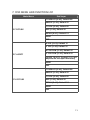
7. OSD MENU AND FUNCTION LIST
Main Menu
2nd Layer
"&,;%,<>@J\!+^
_;`bf,<>@J\!+J{
"|;<>@J\!+J{
PC PICTURE
f}<>@J\!+J{
!,%`|<>@J\!+{<
RESET
EXIT
f`#<>@J\!+J{
`#<>@J\!+J{
f`,`&<>@J\!+J{
PC ASPECT
`,`&<>@J\!+J{
f% <>@J\ !+ {@ depend on the input resolution)
RESET
EXIT
"&,;%,<>@J\!+^
_;`bf,<>@J\!+J{
"|;<>@J\!+J{
CV PICTURE
f}<>@J\!+J{
!,%`|<>@J\!+{<
RESET
EXIT
11
f%<>@J\!+J{
||<>@J\!+J{
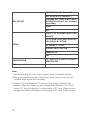
KEY ADJUST
CHROMA KEY: (RED/BLACK/BLUE/
GREEN)*Reset will not change
this setting
RESET
Exit
OUTPUT: PC IN/VIDEO IN/PC KEY/
MIXER*3
CV SYSTEM: NTSC/NTSC4.43/PAL/
PAL-M/PAL-N/ SECAM
SETUP
PC ZOOM: 1 ~9/OFF
DISPLAY: INFO/OFF/ON
REMOTE 0~3
Exit
INFORMATION
PC INPUT/CV INPUT/OUTPUT/
VERSION/EXIT
Exit
Note:
1. Power resetting will turn output display back to default setting.
!"#$#"%&'()##$*"#*#+!
another back signal will be visible.
3. Output PC IN will display PC input source image, Video IN will
+"!#++"*%+!+%-0
")*)##+"!#*5++"*
image and Mixer will display a mix image of PC and Video source.
12
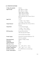
8. SPECIFICATIONS
S-Video Bandwidth
["[{W!
Input Format
;<=<>=>[W!
>==;==>[W!
?=@<E;>>[W!
?@>=?=@<>[W!
?;==?@==;=W!
NTSC, NTSC4.43, PAL, PAL-M, PAL-N,
SECAM
Input Port
?$%
?*?*^E[
?#^*?*^E[
Output Format
NTSC, NTSC4.43, PAL, PAL-M, PAL-N,
SECAM
Output Port
?$%$
?*?*^E[
?#^*?*^E[
ESD Protection
Human Body model:
>*^
± 4kV(contact discharge)
Power Supply
5V/2.6A DC (US/EU Standards, CE/
x%%XY
Dimensions (mm)
@~;?@~]<[W
Weight(g)
400
Chassis Material
Plastic
Silkscreen Color
Black
Operating Temperature
=%
<=%X~@x
?=<x
Storage Temperature
^@=%
;=%X^<x
?<=x
Relative Humidity
@=
=}W^
Power Consumption
4.6 W
13
9. CONNECTION AND INSTALLATION
DVD
PC IN
RS-232
INPUT
PC OUT
S IN
V IN
S IN
OUTPUT
V OUT
S OUT
V IN
PC or Note Book/MAC
14
VGA Monitor
TV (N/P/S)
DC 5V
10. ACRONYMS
ACRONYM
COMPLETE TERM
15
ZZZF\SHXURSHFRP