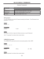
1
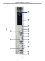
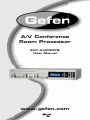
®
A/V Conference
Room Processor
EXT-AVCONFS
User Manual
www.gefen.com
ASKING FOR ASSISTANCE
Technical Support:
Telephone
Fax
(818) 772-9100
(800) 545-6900
(818) 772-9120
Technical Support Hours:
8:00 AM to 5:00 PM Monday thru Friday Pacific Time
Write To:
Gefen, LLC
c/o Customer Service
20600 Nordhoff St
Chatsworth, CA 91311
www.gefen.com
[email protected]
Notice
Gefen, LLC reserves the right to make changes in the hardware, packaging and
any accompanying documentation without prior written notice.
A/V Conference Room Processor
is a trademark of Gefen LLC
HDMI, the
logo, and High-Definition Multimedia Interface are
trademarks or registered trademarks of HDMI Licensing in the United States and
other countries.
Manufactured under license from Dolby Laboratories.
Dolby, Pro Logic, and the double-D symbol
are registered trademarks of Dolby Laboratories.
© 2011 Gefen, LLC, All Rights Reserved
All trademarks are the property of their respective owners.
Rev A1
CONTENTS
1
Introduction
2
Operation Notes
3
Features
4
Front Panel Layout
5
6
7
8
9
Front Panel Descriptions
Back Panel Layout
Back Panel Descriptions
Front Panel Button Layout
Front Panel Button Descriptions
10 IR Remote Control Layout
11
IR Remote Control Descriptions
12
Installing the IR Remote Control Unit
13
IR Remote Control Unit Configuration
14 Connecting the A/V Conference Room Processor
15
Wiring Diagram
16 Front Panel
19 Menu System
27 RS-232 Serial Commands
27
Audio Commands
37
General Commands
39
Video Commands
48 Main Menu System Summary
49
Video Menu Summary
52
Color Menu Summary
54
Output Menu Summary
55
OSD Menu Summary
58
Audio Menu Summary
62
Speaker Menu Summary
66 Mounting Plate Installation
67 Specifications
68 Warranty
INTRODUCTION
Congratulations on your purchase of the A/V Conference Room Processor. Your
complete satisfaction is very important to us.
Gefen
Gefen delivers innovative, progressive computer and electronics add-on solutions
that harness integration, extension, distribution and conversion technologies.
Gefen’s reliable, plug-and-play products supplement cross-platform computer
systems, professional audio/video environments and HDTV systems of all sizes
with hard-working solutions that are easy to install and simple to operate.
The Gefen A/V Conference Room Processor
Integrating multiple audio/video sources in a professional setting has never been
easier. Gefen’s new A/V Conference Room Processor with built-in audio amplifier
connects set top boxes, Blu-ray players, gaming consoles, computers and more.
Video is scaled and output in HDMI format with cinema-quality scaling up to 2K
or 1080p Full HD resolution, supporting large-scale HDTV displays. Multichannel
surround audio (Dolby® or LPCM) is mixed down to two-channel stereo plus support for a powered subwoofer. A built-in two-channel audio amplifier delivers 25
watts per channel from digital and analog sources, ideal for creating high-fidelity
sound in the conference room environment. Two speakers may be connected
directly to the amplifier binding posts for “plug and play” installation in any conference room, educational facility or presentation venue.
How It Works
Connect each video input source and corresponding audio source to connectors
on the front or rear panel. Power up the A/V Conference Room Processor. The
buttons on the front panel are used to select the active A/V source. Use the LCD
menu system to select the scaler output resolution and desired A/V processing
functions. The A/V Conference Room Processor will convert the selected A/V
inputs to HDMI video output with two-channel analog line-level and speaker-level
with powered subwoofer support.
1
OPERATION NOTES
PLEASE READ THESE NOTES BEFORE INSTALLING OR
OPERATING THE A/V CONFERENCE ROOM PROCESSOR
•
The A/V Conference Room Processor has three (3) separate RCA outputs
which are intended to be used with a separate audio amplifier. Up to six
channels of audio can be down-mixed to left, right, and subwoofer.
•
This unit will support the following audio formats:
LPCM (up to 6 channels)
Dolby Digital (AC-3 up to 6 channels)
•
This unit will accept sources that use Deep Color.
2
FEATURES
Features
•
Scales and outputs resolutions up to 1080p, 2K, and 1920x1200
•
Switches and converts various A/V sources to HDMI
•
Dolby Digital™ decoding and processing
•
Advanced EDID Management
•
High performance frame rate conversion engine
•
Auto 3:2 pull-down and 2:2 pull-down detection and recovery
•
Aspect Ratio Control
•
Built-in menu system
•
RS-232 Control
•
Field upgradable firmware
•
Rack-mountable (rack ears included)
Package Includes
•
•
•
•
•
(1) A/V Conference Room Processor
(1) 6 ft. HDMI cable (M-M)
(1) 24 V DC Power Supply
(1) Set of Rack Ears
(1) User Manual
3
1
3
2
4
5
7
6
8
9
11
10
12
Front
13
14
15
FRONT PANEL LAYOUT
4
FRONT PANEL DESCRIPTIONS
1
Analog L/R (RCA) Input
Connect a L/R RCA stereo pair from the Component 1 source to this input.
2
S/PDIF Input
Connect a Coax cable, as part of the Component 1 source, to this input.
3
TOSLINK Input
Connect an Optical cable, as part of the Component 1 source, to this input.
4
Component 1 Input
Connect the red, green, and blue cables from the Component 1 video
source to these inputs.
5
Analog L/R (RCA) Input
Connect a L/R RCA stereo pair, the part of the VGA source, to these inputs.
6
S/PDIF Input
Connect a Coax cable, as part of the VGA source, to this input.
7
Optical (TOSLINK) Input
Connect an Optical cable, as part of the VGA source, to this input.
8
VGA (DB-15) Input
Connect the VGA cable from the VGA video source to this input.
9
Analog L/R (RCA) Input
Connect a L/R RCA stereo pair, the part of the DVI source, to these inputs.
10 S/PDIF Input
Connect a Coax cable, as part of the DVI source, to this input.
11 TOSLINK Input
Connect an Optical cable, as part of the DVI source, to this input.
12 VGA Input
Connect a DVI cable from the DVI video source to this input.
13 HDMI Input
Connect an HDMI cable from the Hi-Def source to this input.
14 Main LCD Display
This display will show important status information and will be used to make
adjustments to features in the Menu System.
15 Front Panel Buttons
Provides push-button control of the A/V Conference Room Processor. See
page 8 for details.
5
1
2
3
4
5
7
6
8
9
Back
10
11
12
13
BACK PANEL LAYOUT
6
BACK PANEL DESCRIPTIONS
1
HDMI Output
Connect an HDMI cable from the A/V Conference Room Processor to an
HDTV display.
2
Analog L/R (RCA) Input
Connect a L/R RCA stereo pair from the Component 2 source to this input.
3
S/PDIF Input
Connect a Coax cable, as part of the Component 2 source, to this input.
4
Component 2 Input
Connect the red, green, and blue cables from the Component 2 video
source to these inputs.
5
Analog L/R (RCA) Input
Connect a L/R RCA stereo pair, the part of the DVI 2 source, to these
inputs.
6
S/PDIF Input
Connect a Coax cable, as part of the DVI 2 source, to this input.
7
TOSLINK Input
Connect an Optical cable, as part of the DVI 2 source, to this input.
8
DVI Input
Connect a DVI cable from the DVI 2 video source to this input.
9
RS-232 Serial Port
This port is used for serial communication using an RS-232 control device.
Access to certain features are only available through the RS-232 interface.
10 Analog L/R (RCA) Output
Connect a L/R RCA stereo pair from this output to a L/R RCA stereo input
pair on the A/V equipment.
11 LFE (Subwoofer) Output
Connect a subwoofer to this output using a single RCA cable.
12 Front Left / Front Right Speaker Terminals
These speaker binding post terminals will accept spade lug, banana
plug, dual banana plug, bare wire, and pin style connectors.
13 24 V DC Power Receptacle
Connect the included 24 V DC power supply to this receptacle.
7
FRONT PANEL BUTTON LAYOUT
The A/V Conference Room Processor uses a series of push buttons, located on
the front panel, for all input selection and feature functions. All status information,
such as the input and output resolutions are always available on the front panel
LCD Screen. User adjustable features, such as color correction and aspect ratio,
can be navigated and adjusted by referencing either the LCD Screen or the OnScreen Display (OSD).
All menu navigation and adjustments are accomplished by using the front panel
buttons. Please review the front panel buttons below.
2
1
3
5
6
4
9
7
8
8
11
12
10
14
13
FRONT PANEL BUTTON DESCRIPTIONS
1
Left Cursor Button
This button is used to navigate the Menu System and change settings
by moving the cursor to the left.
2
Up Button
This button is used to navigate the Menu System and change settings
by moving the cursor up. This button is also used for increasing the
audio volume in the Status Screen (see page 17).
3
Down Button
This button is used to navigate the Menu System and change settings
by moving the cursor down. This button is also used for decreasing the
audio volume in the Status Screen (see page 17).
4
Right Cursor Button
This button is used to navigate the Menu System and change settings
by moving the cursor to the right.
5
Select Button
This button is used to accept and save a current setting in the Menu
System.
6
Menu Button
This button will activate the Menu System which allows changes to
audio output.
7
Exit Button
Used to exit the configuration menu.
8
Comp 2 Button
Selects Component 2 as the A/V input source.
9
Comp 1 Button
Selects Component 1 as the A/V input source.
10 DVI 1 Button
Selects DVI 1 as the A/V input source.
11 DVI 2 Button
Selects DVI 2 as the A/V input source.
12 VGA Button
Selects VGA as the A/V input source.
13 HDMI Button
Selects HDMI as the A/V input source.
14 Mute Button
Mutes the currently selected audio input.
9
IR REMOTE CONTROL LAYOUT
17
15
1
11
2
10
16
12
14
13
3
9
4
5
8
6
7
1
Mute Button
Enables / disables muting of the audio output signal.
2
Video Format Button
Cycles through the available output resolutions. See page 22 for a list of
the available Output Resolutions.
3
Pict Mode Button
Cycles through the different picture modes (Standard, Movie, Vivid, and
User). See page 19 for details.
4
DVI 1 2 Button
Toggles between the DVI 1 and DVI 2 A/V inputs.
5
Comp 1 2 Button
Toggles between the COMP 1 and COMP 2 A/V inputs.
6
HDMI Button
Selects the HDMI video input.
10
IR REMOTE CONTROL DESCRIPTIONS
7
Audio Input Button
Cycles between the available audio inputs for the selected video input.
8
PC VGA
Selects the VGA video input.
9
Exit Button
Exits a menu or sub-menu within the built-in menu system.
10 Menu Button
Places the Conference Room Processor in Menu Mode, allowing
adjustment of scaling, color correction, and other features.
11 Power Button
Used to turn on or turn off the Conference Room Processor.
12 Left Cursor Button
Used to navigate left within the menu system.
13 Down Cursor Button
Used to navigate down within the menu system. This button is also used to
decrease the volume.
14 Right Cursor Button
Used to navigate right within the menu system.
15 Up Cursor Button
Used to navigate up within the menu system. This button is also used to
increase the volume.
16 Enter Button
Used to confirm / save a changes within the built-in menu system.
17 Activity Indicator
This LED will be activated momentarily each time a button is pressed.
11
INSTALLING THE IR REMOTE CONTROL UNIT
Installing the Battery
1.
Remove the battery cover on the back of the IR Remote Control unit.
2.
Insert the included battery into the open battery slot. The positive (+) side of
the battery should be facing up.
3.
Replace the battery cover.
The Remote Control unit ships with two batteries. One battery is required for
operation and the other battery is a spare.
Battery Slot
CAUTION: Risk of explosion if battery is replaced by an incorrect
type. Dispose of used batteries according to the instructions.
12
IR REMOTE CONTROL UNIT CONFIGURATION
Setting the IR Remote Control Channel
In the event that IR commands from other remote controls interfere with the
supplied IR Remote Control unit, changing the IR Remote Control’s IR channel
will fix the problem. The IR Remote Control unit has a bank of DIP switches used
for setting the IR channel.
The DIP switch bank is located underneath the battery cover.
Channel 0:
Default
Channel 1:
1
2
Channel 2:
1
2
1
2
Channel 3:
1
2
Battery compartment of the IR remote
showing the exposed DIP Switch bank
between the battery chambers.
It is important that the IR channel on the Remote Control unit, matches the IR
channel set on the Gefen A/V Conference Room Processor. For example, if
both DIP switches on the IR Remote Control unit are set to IR channel 0 (both
DIP switches down), then the A/V Conference Room Processor must also be
set to IR channel 0. See page 36 on how to change the IR channel on the A/V
Conference Room Processor.
13
CONNECTING THE A/V CONFERENCE ROOM PROCESSOR
How to Connect the A/V Conference Room Processor
1.
2.
Connect video source devices to the A/V Conference Room Processor video
inputs. The following inputs are available:
Front Panel
Back Panel
HDMI
N/A
DVI-I (analog and digital DVI)
DVI-D (digital DVI)
VGA
N/A
Component
Component
Connect audio sources to the A/V Conference Room Processor audio inputs.
The following inputs are available:
Front Panel
Analog L/R
TOSLINK
S/PDIF
N/A
N/A
N/A
DVI-I
●
●
●
VGA
●
●
●
Component
●
●
●
Back Panel
Analog L/R
TOSLINK
S/PDIF
DVI-I
●
●
●
Component
●
N/A
●
HDMI (embedded)
NOTE: All inputs, except for HDMI, are able to accept both analog and
digital audio sources. Therefore, each input has a selector option in the OSD
that will allow the user to select the type of audio used.
3.
Connect an HDMI cable from the A/V Conference Room Processor to an
HDTV display.
4.
Connect the included 24 V DC power supply to the A/V Conference Room
Processor then connect the AC power cord to an available electrical socket.
14
CONNECTING THE A/V CONFERENCE ROOM PROCESSOR
Wiring Diagram for the A/V Conference Room Processor
SUBWOOFER AUDIO (RCA) CABLE
DVI Source
DVI / HDMI Source
DIGITAL AUDIO (TOSLINK)
DIGITAL AUDIO (COAX)
ANALOG AUDIO (RCA)
COMPONENT
SPEAKER
CABLE
CABLE
CABLE
CABLE
CABLE
RS-232
HDMI
VGA
DVI
CABLE
CABLE
CABLE
CABLE
Component Source
VGA Source
Component Source
Speaker
Speaker
Subwoofer
HDMI Display
RS-232
RS
232 Controller
C t ll
Audio Receiver
EXT-AVCONFS
ATTENTION: This product should always be connected to a
grounded electrical socket.
15
FRONT PANEL
Status Screen
The Status Screen displays information regarding the current settings of the
Audio Processor. The Status Screen is also used in conjunction with navigating
the built-in Menu System.
After powering on the Audio Amplifier, the Standby Screen will be displayed:
A/V Input
Displays the selected
A/V input
Input Resolution
Displays the input
video resolution
Audio Gain
Displays the
audio gain (volume)
Output Resolution
Displays the output
video resolution
If no video source is connected to the Conference Room Processor
or if a loss of video signal occurs, then “Loss” will be displayed as
the input resolution on the Status Screen.
Indicates that a lost of
the input video signal has
occurred.
16
FRONT PANEL
Adjusting the Volume
Use the Up Button and Down Button to increase or decrease the audio gain
in the Status Screen. Audio gain can be reduced to a minimum of -60 dB and
to a maximum of +10 dB. Each time these buttons are pressed, the volume is
increased or decreased by 1 dB.
To increase or decrease the audio gain at a faster rate, press and
hold down either of these buttons until the desired volume is
achieved.
Increase
Volume
Decrease
Volume
Current
Volume
Muting
Use the Mute button on the front panel to silence the audio output. To disable the
mute function, press the Mute button again. The ▲ and ▼ buttons (volume)
can also be used to disable muting.
Enable / disable
muting
17
FRONT PANEL
Firmware Version
To display the firmware version of the A/V Conference Room Processor, press
either the ◄ or ► buttons on the front panel:
Pressing the ◄ or ► will cycle between
the Firmware Version screen and the
information on the Status Screen.
Selecting the Input Source
Use the buttons on the front panel to select the input source.
Front Panel
Button
Input
Location
LCD Display
Name
COMP1
Component
Front Panel
Comp1
VGA
VGA
Front Panel
PC
DVI1
DVI-I
Front Panel
DVI1
HDMI
HDMI
Front Panel
HDMI
COMP2
Component
Back Panel
Comp2
DVI2
DVI-I
Back Panel
DVI2
18
MENU SYSTEM
Video Menu
To access the Video Menu, press the Menu button on the front panel.
Use the ▼ or ▲ buttons to highlight the Video Menu icon. Press the Menu
button to enter the Video Menu. Use the ▼ or ▲ buttons to scroll through each
of the parameters. Press the Menu button to change the selected parameter.
Use the ◄ or ► buttons to increase or decrease the values.
Picture Mode
Preset and user configuration settings for different viewing scenarios. Preset settings will not allow user adjustment. Only the USER option will allow customized
video settings. The USER settings are saved.
•
Standard - useful for general content
•
Movie - useful for dimly lit environments
•
Vivid - useful for accentuating colors for a more vibrant image
•
User - user configuration settings
Contrast
Adjusts the Contrast by increments of 1. Minimum value: 1, Maximum value:
100.
Brightness
Adjusts the Brightness by increments of 1. Minimum value: 1, Maximum value:
100.
Hue
Adjusts the Hue by increments of 1. Minimum value: 1, Maximum value: 100.
Saturation
Adjusts the Saturation level by increments of 1 or -1. Minimum value: 1,
Maximum value: 100.
Sharpness
Adjusts the sharpness in increments of 1 on a scale of 1 to 100 (default 50).
19
MENU SYSTEM
Scale
Sets the scaling adjustment. Options are: Full, Overscan, Underscan, Letterbox
U.S. (Underscan), PanScan U.S. (Underscan), Letterbox Full, and PanScan Full.
•
Full
Stretches the image to fill the screen
•
Overscan
Stretches the image to fullscreen and just beyond the border of the display
•
Underscan
Stretches the image to fullscreen and just within the border of the screen
•
Letterbox U.S. (Underscan)
Stretches the image to 16:9 aspect ratio with underscan
•
PanScan U.S. (Underscan)
Stretches the image to 4:3 aspect ratio with underscan
•
Letterbox Full
Stretches the image to 16:9 aspect ratio without underscan
•
PanScan Full
Stretches the image to 4:3 aspect ratio without underscan
NR (Noise Reduction)
Reduces noise artifacts in the picture. This option is only available when the
input signal is 480i or 480p.
H-Position
Specifies the horizontal position of the input signal.
V-Position
Specifies the vertical position of the input signal.
Input
Specifies the input video signal. Options are HDMI, DVI1, DVI2, Component,
and VGA.
Exit
Exits the Video Menu and returns control to the Main Menu.
20
MENU SYSTEM
Color Menu
To access the Output Menu, press the Menu button. Use the ▼ or ▲ buttons
to highlight the Output Menu icon. Press the Menu button to enter the Output
Menu. Use any of the arrow buttons on the front panel to select the desired output resolution. Press the Enter button to enable the selected output resolution.
Select the Exit option to exit the Color Menu and return control to the Main Menu.
Color Tone
•
Normal
Use for general content.
•
Warm
Red-shifts RGB values for a warmer video color.
•
Cool
Blue-shifts RGB values for a cooler video color.
•
User
Allows individual adjustment of Red, Green, and Blue color components.
Red
Adjusts the Red value by increments of 1. Minimum value: 1, Maximum value:
100.
Green
Adjusts the Green value by increments of 1. Minimum value: 1, Maximum value:
100.
Blue
Adjusts the Blue value by increments of 1. Minimum value: 1, Maximum value:
100.
Exit
Exits the Color Menu and returns control to the Main Menu.
21
MENU SYSTEM
Output Menu
To access the Output Menu, press the Menu button. Use the ▼ or ▲ buttons
to highlight the Output Menu icon. Press the Menu button to enter the Output
Menu. Use any of the arrow buttons on the front panel to select the desired output resolution. Press the Enter button to enable the selected output resolution.
Select the Exit option to exit the Color Menu and return control to the Main Menu.
VGA
480i
576i
WXGA
SVGA
480p
576p
WSXGA
XGA
720p60
720p50
WUXGA
SXGA
1080i60
1080i50
UXGA
1080p60
1080p50
1080p-1
1080p-2
1080p-3
Native*
Exit
2K
* The Native option will select the native resolution of the connected display based
on the EDID from the display.
The Output Menu contains three frame rate conversion modes:
•
1080p-1
No frame rate conversion.
•
1080p-2
Converts all frame rates (except 24) to 60.
•
1080p-3
Converts all frame rates (except 24) to 50.
If a resolution that is not supported by the display is selected, then the
on-screen Menu will no longer be visible. To correct this, press the
OUTPUT button on the RMT-SR-IR remote control and cycle through
the output resolutions until a supported mode is displayed.
Exit
Exits the Output Menu and returns control to the Main Menu.
22
MENU SYSTEM
OSD Menu
To access the OSD Menu, press the Menu button. Use the ▼ or ▲ buttons to
highlight the OSD Menu icon. Press the Menu button to enter the OSD Menu.
Use the ◄ or ► buttons to select the desired output resolution. Press the Enter
button to enable the selected output resolution. Use the ◄ or ► buttons to
select the Exit option to exit the Speaker Menu and return control to the Main
Menu.
H-Position (Horizontal Position)
Adjusts the horizontal position on the Menu System on the screen. Minimum value:
1, Maximum value: 100.
V-Position (Vertical Position)
Adjusts the vertical position of the Menu System on the screen. Minimum value: 1,
Maximum value: 100.
Time Out
Adjusts the amount of time (in seconds) before the OSD automatically closes.
Minimum value: 1, Maximum value: 100.
Background
Sets the transparency level of the OSD background. Minimum value: 0, Maximum
value: 8.
Remote Channels
Sets the remote channel for use with the IR Remote Control Unit. Minimum value: 0,
Maximum value: 3.
If the selected Remote Channel in this menu and does not match the
IR Channel set in the RMT-SR-IR remote, the unit will cease to
respond to IR commands from the remote.
Exit
Exits the OSD Menu and returns control to the Main Menu.
23
MENU SYSTEM
Audio Menu
To access the Audio Menu, press the Menu button. Use the ▼ or ▲ buttons to
highlight the Audio Menu icon. Press the Menu button to enter the Audio Menu.
Use the + or - buttons to select the desired output resolution. Press the Enter
button to enable the selected output resolution. Use the + or - buttons to select
the Exit option to exit the Audio Menu and return control to the Main Menu.
DVI1
Selects the audio input for DVI In 1. Options are: Analog, S/PDIF, or TOSLINK.
DVI2
Selects the audio input for DVI In 2. Options are: Analog, S/PDIF, or TOSLINK.
VGA
Selects the audio input for VGA In. Options are: Analog, S/PDIF, or TOSLINK.
Comp1
Selects the audio input for Component In 1. Options are: Analog, S/PDIF, or
TOSLINK.
Comp2
Selects the audio input for Component In 2. Options are: Analog or S/PDIF.
Bass
Allows adjustment of the bass. Minimum value: -12 dB, Maximum value: +12 dB
Treble
Allows adjustment of the treble. Minimum value: -12 dB, Maximum value: +12 dB
DRC (Dynamic Range Control)
Dynamic Range Compression (DRC) is a feature that will apply compression of
loud sounds over a certain threshold while quiet sounds remain unprocessed.
This feature is useful for reducing loud noises that will overpower quieter sounds.
Enhancement
Audio enhancement. Options are: Off, Night, Voice, or Volume
Delay
Sets the audio delay. Use this feature to compensate for any loss of audio sync in
the video. Options are: Off, 40 ms, 110 ms, or 150 ms.
Sound
Used to enable or disable audio muting. Options are: Off or On.
Exit
Exits the Audio Menu and returns control to the Main Menu.
24
MENU SYSTEM
Speakers Menu
To access the Speakers Menu, press the Menu button. Use the ▼ or ▲
buttons to highlight the Speakers Menu icon. Press the Menu button to enter the
Speaker Menu. Use the ◄ or ► buttons to select the desired option. Use the +
or - buttons to select the Exit option to exit the Speaker Menu and return control
to the Main Menu.
Size
Selects the size of the speakers (left / right). Options are: Large or Small.
Subwoofer
Selects the presence or absence of the subwoofer. Options: On or Off. If a
subwoofer is not connected, set this option to Off.
Subwoofer Frequency
Selects the cutoff frequency of the subwoofer. Options are: 50 Hz, 60 Hz, or 90 Hz.
Line Out Mode
Selects how the volume is controlled when the A/V Conference Room Processor
is connected to an external amplifier using RCA (analog) connectors. Options are
Fixed or Pre-Amp. If the volume is to be controlled by the external amplifier, set this
option to Fixed.
HDMI Out Mode
Selects how the volume is controlled when the A/V Conference Room Processor is
connected to an external amplifier. This option differs from the Line Out Mode in that
only the HDMI audio is affected. Options are Fixed or Pre-Amp. If the volume is to
be controlled by the external amplifier, set this option to Fixed.
Distance L
Sets the distance for the left speaker. Minimum value: 0 m, Maximum value: 10 m.
Distance R
Sets the distance for the right speaker. Minimum value: 0 m, Maximum value: 10 m.
Distance Sub
Sets the distance for the subwoofer. Minimum value: 0 m, Maximum value: 10 m.
Level L
Sets the offset volume level for the left speaker. Minimum value: +0 dB, Maximum
value: +10 dB
Level R
Sets the offset volume level for the left speaker. Minimum value: +0 dB, Maximum
value: +10 dB
25
MENU SYSTEM
Level Sub
Sets the offset volume level for the left speaker. Minimum value: +0 dB, Maximum
value: +10 dB
Exit
Exits the Speaker Menu and returns control to the Main Menu.
26
RS-232 SERIAL COMMANDS
54321
12345
9876
6789
Only Pins 2 (RX), 3 (TX), and 5 (Ground) are used on the RS-232 serial interface
RS232 Settings
Bits per second ............................................................................................ 19200
Data bits ............................................................................................................... 8
Parity ............................................................................................................. None
Stop bits ................................................................................................................1
Flow Control .................................................................................................. None
Audio Commands
Command
Description
ADELAY
Sets the audio delay
AENHNCE
Improves the speech intelligibility
AIN
Selects the audio input source
BASS
Increases or decreases the bass
DFL
Sets the distance for the Front Left speaker
DFR
Sets the distance for the Front Right speaker
DRC
Adjusts the Dynamic Range Control
DSB
Sets the distance of the Subwoofer
FLR
Sets the size of the Front Left / Front Right speakers
LFV
Sets the Left Front speaker volume
MUTE
Enables / disables audio muting
RTV
Sets the Right Front speaker volume
SUB
Enables / disables the subwoofer
SUBV
Adjusts the subwoofer volume
SUBX
Sets the crossover frequency
TREB
Increases / decreases the treble
VOL
Increases / decreases the overall output volume
27
RS-232 SERIAL COMMANDS
Command Syntax
The syntax for each command is as follows:
CommandName [space] param1 [space] param2...paramN \r
The command syntax is NOT case sensitive.
ADELAY Command
The ADELAY command sets the audio delay.
Syntax:
ADELAY param1
Parameters:
param1
Value
Value
Meaning
Off
Audio delay off
40
40 ms delay
110
110 ms delay
150
150 ms delay
Notes:
Use ? for param1 to retrieve the current value.
28
RS-232 SERIAL COMMANDS
AENHNCE Command
The AENHNCE command improves the speech intelligibility.
Syntax:
AENHNCE param1
Parameters:
param1
Mode
Mode
Meaning
Off
Enhance mode off
Night
Low volume for night viewing
Voice
Dialog becomes more clear
Volume
Emphasized audio gain
Notes:
Use ? for param1 to retrieve the current value.
AIN Command
The AIN command set the audio input source.
Syntax:
AIN param1
Parameters:
param1
Value
Value
Meaning
LR
RCA input
Coax
S/PDIF input
Opti
TOSLink input
Notes:
Use ? for param1 to retrieve the current value.
29
RS-232 SERIAL COMMANDS
BASS Command
The BASS command sets the bass level.
Syntax:
BASS param1
Parameters:
param1
Level
[-12 ...12]
Notes:
The + or - character can also be used, instead of specifying a value, in order to
increase or decrease the bass level by 1 dB.
Use ? for param1 to retrieve the current value.
Example:
bass +
bass bass 5
// increases the bass level by 1 dB
// decreases the bass level by 1 dB
// sets the bass level to +5 dB
DFL Command
The DFL command sets the distance of the Front Left speaker.
Syntax:
DFL param1
Parameters:
param1
Level
[0 ...10]
Notes:
The + or - character can also be used, instead of specifying a value, in order to
increase or decrease the Front Left distance by 1 foot intervals.
Use ? for param1 to retrieve the current value.
30
RS-232 SERIAL COMMANDS
DFR Command
The DFL command sets the distance of the Front Right speaker.
Syntax:
DFR param1
Parameters:
param1
Level
[0 ...10]
Notes:
The + or - character can also be used, instead of specifying a value, in order to
increase or decrease the Front Right distance by 1 foot intervals.
Use ? for param1 to retrieve the current value.
DRC Command
The DRC command adjusts the Dynamic Range Control.
Syntax:
DRC param1
Parameters:
param1
Value
Value
Meaning
OFF
Turn DRC Off
ON
Turn DRC On
TGL
Toggle DRC
Notes:
Setting param1 to TGL will automatically toggles the current state of the DRC
command. This is the non-implicit form of switching DRC ON or OFF.
Use ? for param1 to retrieve the current value.
31
RS-232 SERIAL COMMANDS
DSB Command
The DSB sets the distance of the Subwoofer.
Syntax:
DSB param1
Parameters:
param1
Level
[0 ...10]
Notes:
The + or - character can also be used, instead of specifying a value, in order to
increase or decrease the Subwoofer distance by 1 foot intervals.
Use ? for param1 to retrieve the current value.
FLR Command
The FLR command sets the size of the Front Left and Front Right speakers.
Syntax:
FLR param1
Parameters:
param1
Value
Value
Meaning
Small
Small Speaker
Large
Large Speaker
Notes:
Use ? for param1 to retrieve the current value.
32
RS-232 SERIAL COMMANDS
LFV Command
The LFV command sets the Front Left speaker volume.
Syntax:
LFV param1
Parameters:
param1
Level
[-10...10]
Notes:
The + or - character can also be used, instead of specifying a value, in order to
increase or decrease the Front Left speaker volume by 1 dB intervals.
Use ? for param1 to retrieve the current value.
MUTE Command
The MUTE command enables or disables audio muting.
Syntax:
MUTE param1
Parameters:
param1
Value
Value
Meaning
OFF
Turn Muting Off
ON
Turn Muting On
TGL
Toggle Muting
Notes:
Setting param1 to TGL will automatically toggles the current state of the muting
command. This is the non-implicit form of enabling or disabling audio muting.
Use ? for param1 to retrieve the current value.
33
RS-232 SERIAL COMMANDS
RTV Command
The RTV command sets the Front Right speaker volume.
Syntax:
RTV param1
Parameters:
param1
Level
[-10...10]
Notes:
The + or - character can also be used, instead of specifying a value, in order to
increase or decrease the Front Right speaker volume by 1 dB intervals.
Use ? for param1 to retrieve the current value.
SUB Command
The SUB command enables or disables the subwoofer. If a subwoofer is not
connected, the subwoofer should be disabled.
Syntax:
SUB param1
Parameters:
param1
Value
Value
Meaning
OFF
Disable the subwoofer
ON
Enable the subwoofer
TGL
Toggle subwoofer state
Notes:
Setting param1 to TGL will automatically toggle the current state of the
subwoofer. This provides a non-implicit form of enabling or disabling the
subwoofer.
Use ? for param1 to retrieve the current value.
34
RS-232 SERIAL COMMANDS
SUBV Command
The SUBV command sets the subwoofer volume.
Syntax:
SUBV param1
Parameters:
param1
Level
[-10...10]
Notes:
The + or - character can also be used, instead of specifying a value, in order to
increase or decrease the subwoofer volume by 1 dB intervals.
Notes:
Use ? for param1 to retrieve the current value.
SUBX Command
The SUBX command adjusts the crossover frequency. This specified value
defines the point, on the frequency spectrum, where are rolled off to the
subwoofer.
Syntax:
SUBX param1
Parameters:
param1
Value
Value
Meaning
50
50 Hz roll-off
60
60 Hz roll-off
90
90 Hz roll-off
Notes:
Use ? for param1 to retrieve the current value.
35
RS-232 SERIAL COMMANDS
TREB Command
The TREB command sets the treble subwoofer volume.
Syntax:
TREB param1
Parameters:
param1
Level
[-12...12]
Notes:
The + or - character can also be used, instead of specifying a value, in order to
increase or decrease the treble level by 1 dB intervals.
Use ? for param1 to retrieve the current value.
VOL Command
The VOL sets the overall output audio signal.
Syntax:
VOL param1
Parameters:
param1
Value
[-81...12]
Notes:
The + or - character can also be used, in place of specifying a value, to increase
or decrease the output volume by 1 dB intervals.
Use ? for param1 to retrieve the current value.
36
RS-232 SERIAL COMMANDS
General Commands
Command
Description
IR
Sets the IR channel
OSDHPOS
Sets the horizontal position of the OSD
OSDVPOS
Sets the vertical position of the OSD
POWER
Turns the Scaler ON or OFF
IR Command
The IR command sets the IR Channel used by the Scaler. The IR channel can
be set to 1, 2, 3, or 4.
Syntax:
IR param1
Parameters:
param1
Level
[1...4]
Notes:
Set param1 to ALL to have the Scaler receive on any IR channel.
Use ? for param1 to retrieve the current value.
OSDHPOS Command
The OSDHPOS command sets the horizontal position of the OSD.
Syntax:
OSDHPOS param1
Parameters:
param1
HPos
[0...100]
Notes:
Use ? for param1 to retrieve the current value.
37
RS-232 SERIAL COMMANDS
OSDVPOS Command
The OSDVPOS command sets the vertical position of the OSD.
Syntax:
OSDVPOS param1
Parameters:
param1
VPos
[0...100]
Notes:
Use ? for param1 to retrieve the current value.
POWER Command
The POWER command turns the Scaler ON or OFF.
Syntax:
OSDVPOS param1
Parameters:
param1
State
Value
Meaning
Off
Power Off
On
Power On
TGL
Toggle Power State
Notes:
Setting param1 to TGL will automatically toggle the current power state. This
provides a non-implicit form of turning the Scaler ON or OFF.
Use ? for param1 to retrieve the current value.
38
RS-232 SERIAL COMMANDS
Video Commands
Command
Description
BLUE
Set the blue color component value
BRTNESS
Sets the brightness value
CLRTMP
Sets the color temperature
CONTRST
Sets the contrast level
GREEN
Sets the green color component value
HUE
Sets the hue
NR
Sets the noise reduction level
OUT
Sets the output resolution
PCHPOS
Adjusts the horizontal position of the output signal
PCVPOS
Adjusts the vertical position of the output signal
PMODE
Sets the picture mode
RED
Sets the red color component value
SATURTN
Sets the saturation level
SHARP
Sets the sharpness level
SIZE
Sets the picture mode
VIN
Sets the video input source
BLUE Command
The BLUE command sets the blue color component value.
Syntax:
BLUE param1
Parameters:
param1
Value
[0...100]
Notes:
The + or - character can also be used, in place of specifying a value, to increase
or decrease the color component value by intervals of 1.
Use ? for param1 to retrieve the current value.
39
RS-232 SERIAL COMMANDS
BRTNESS Command
The BRTNESS sets the brightness level of the output.
Syntax:
BRTNESS param1
Parameters:
param1
Value
[0...100]
Notes:
The + or - character can also be used, in place of specifying a value, to increase
or decrease the brightness value by intervals of 1.
Use ? for param1 to retrieve the current value.
CLRTMP Command
The CLRTMP command sets the color temperature.
Syntax:
CLRTMP param1
Parameters:
param1
Temperature
Temperature
Meaning
normal
Normal color temperature
warm
Warmer color tone (red)
cool
Cooler color tone (blue)
user
User specified
Notes:
Use ? for param1 to retrieve the current value.
40
RS-232 SERIAL COMMANDS
CONTRST Command
The CONTRST sets the contrast level on the output signal.
Syntax:
CONTRST param1
Parameters:
param1
Value
[0...100]
Notes:
The + or - character can also be used, in place of specifying a value, to increase
or decrease the contrast value by intervals of 1.
Use ? for param1 to retrieve the current value.
GREEN Command
The GREEN command sets the green color component value.
Syntax:
GREEN param1
Parameters:
param1
Value
[0...100]
Notes:
The + or - character can also be used, in place of specifying a value, to increase
or decrease the color component value by intervals of 1.
Use ? for param1 to retrieve the current value.
41
RS-232 SERIAL COMMANDS
HUE Command
The HUE sets the color hue level.
Syntax:
HUE param1
Parameters:
param1
Value
[0...100]
Notes:
The + or - character can also be used, in place of specifying a value, to increase
or decrease the color hue by intervals of 1.
Use ? for param1 to retrieve the current value.
NR Command
The NR command sets the noise reduction value.
Syntax:
NR param1
Parameters:
param1
Mode
Mode
Meaning
off
Noise reduction Off
low
Low noise reduction
mid
Medium noise reduction
high
High noise reduction
Notes:
Use ? for param1 to retrieve the current value.
42
RS-232 SERIAL COMMANDS
OUT Command
The OUT command sets the output resolution.
Syntax:
OUT param1
Parameters:
param1
Resolution
Resolution
Meaning
native
Native resolution of display
vga
640 x 480
svga
800 x 600
xga
1024 x 768
sxga
1280 x 1024
uxga
1600 x 1200
480i
640 x 480i / 720 x 480i
480p
640 x 480p / 720 x 480p
720p60
1280 x 720p
1080i60
1920 x 1080i @ 60 Hz
1080p60
1920 x 1080p @ 60 Hz
576i
720 x 576i
576p
720 x 576p
720p50
1280 x 720p @ 50 Hz
1080i50
1920 x 1080i @ 50 Hz
1080p50
1920 x 1080p @ 50 Hz
wxga
1280 x 768
wsxga
1680 x 1050
wuxga
1920 x 1200
1080p24
1920 x 1080p @ 24 Hz
2k60
2048 x 1080 @ 60 Hz
Notes:
Use ? for param1 to retrieve the current value.
43
RS-232 SERIAL COMMANDS
PCHPOS Command
The PCHPOS command sets the horizontal position of the output signal on the
display.
Syntax:
PCHPOS param1
Parameters:
param1
Value
[0...100]
Notes:
The + or - character can also be used, in place of specifying a value, to move the
picture right (+) or left (-) by intervals of 1.
Use ? for param1 to retrieve the current value.
\PCVPOS Command
The PCVPOS command sets the vertical position of the output signal on the
display.
Syntax:
PCVPOS param1
Parameters:
param1
Value
[0...100]
Notes:
The + or - character can also be used, in place of specifying a value, to move the
picture up (+) or down (-) by intervals of 1.
Use ? for param1 to retrieve the current value.
44
RS-232 SERIAL COMMANDS
PMODE Command
The PMODE command loads a predefined color and brightness calibration which
is applied to the output signal.
Syntax:
PMODE param1
Parameters:
param1
Mode
Mode
Meaning
std
Standard picture mode
mov
Movie mode
vivd
Vivid colors mode
user
User defined
Notes:
Use ? for param1 to retrieve the current value.
RED Command
The RED command sets the green color component value.
Syntax:
RED param1
Parameters:
param1
Value
[0...100]
Notes:
The + or - character can also be used, in place of specifying a value, to increase
or decrease the color component value by intervals of 1.
Use ? for param1 to retrieve the current value.
45
RS-232 SERIAL COMMANDS
SATURTN Command
The SATURTN command sets the saturation level of the output signal.
Syntax:
SATURTN param1
Parameters:
param1
Value
[0...100]
Notes:
The + or - character can also be used, in place of specifying a value, to increase
or decrease the saturation value by intervals of 1.
Use ? for param1 to retrieve the current value.
SHARP Command
The SHARP command sets the sharpness level.
Syntax:
SHARP param1
Parameters:
param1
Value
[0...100]
Notes:
The + or - character can also be used, in place of specifying a value, to increase
or decrease the sharpness by intervals of 1.
Use ? for param1 to retrieve the current value.
46
RS-232 SERIAL COMMANDS
SIZE Command
The SIZE command sets the saturation level of the output signal.
Syntax:
SIZE param1
Parameters:
param1
Size
Size
Meaning
full
Full-screen picture mode
ovscan
Overscan mode
unscan
Underscan mode
ltrbox
Letterbox mode (16:9)
pnscan
Pan-and-Scan (4:3)
Notes:
Use ? for param1 to retrieve the current value.
VIN Command
The VIN command sets the active video input source.
Syntax:
VIN param1
Parameters:
param1
Input
Input
Meaning
comp1
Component input 1
comp2
Component input 2
hdmi
HDMI input
dvi1
DVI input 1
dvi2
DVI input 2
vga
VGA input
Notes:
Use ? for param1 to retrieve the current value.
47
MAIN MENU SYSTEM SUMMARY
Menu
▲
▲
Exit
▲
▲
Exit
▲
▲
Exit
▲
▲
Exit
▲
▲
Exit
▲
Exit
▲
48
VIDEO MENU SUMMARY
Status Screen
▲
▲
Exit
Exit
▲
▲
▲
Standard
Movie
Vivid
▲
User
▲
▲
Exit
▲
Min: 0
Max: 100
▲
▲
▲
Exit
▲
Min: 0
Max: 100
49
VIDEO MENU SUMMARY
▲
Exit
▲
▲
Min: 0
▲
Max: 100
▲
▲
▲
Exit
Min: 0
▲
Max: 100
▲
▲
▲
Exit
Min: 0
▲
Max: 100
50
VIDEO MENU SUMMARY
▲
Exit
▲
▲
Full
▲
Overscan
Underscan
LetterboxUS
PanScan U.S.
Letterbox Full
▲
PanScan Full
▲
▲
Exit
HDMI
▲
DVI1
DVI2
PC
COMP1
COMP2
▲
▲
Exit
51
COLOR MENU SUMMARY
Status Screen
▲
▲
Exit
Exit
▲
▲
▲
User
Normal
Warm
▲
Cool
▲
▲
Exit
▲
Min: 0
Max: 100
▲
▲
▲
Exit
▲
Min: 0
Max: 100
52
COLOR MENU SUMMARY
▲
▲
▲
Exit
Min: 0
▲
Max: 100
▲
▲
Exit
53
OUTPUT MENU SUMMARY
Status Screen
▲
▲
Exit
Exit
▲
▲
▲
VGA
▲
SVGA
Menu
54
576p
XGA
720p50
SXGA
1080i50
UXGA
1080p50
1080p-1
1080p-3
480i
NATIVE
480p
WXGA
720p60
WSXGA
1080i60
WUXGA
1080p60
2K
1080p-2
EXIT
576i
OSD MENU SUMMARY
Status Screen
▲
▲
Exit
▲
▲
Exit
▲
Min: 0
Max: 100
▲
▲
▲
Exit
▲
Min: 0
Max: 100
▲
55
OSD MENU SUMMARY
▲
Exit
▲
▲
▲
Min: 0
Max: 100
▲
Exit
▲
▲
▲
Min: 0
Max: 100
▲
▲
▲
Exit
▲
1
2
3
4
56
OSD MENU SUMMARY
▲
▲
Exit
57
AUDIO MENU SUMMARY
Status Screen
▲
▲
Exit
Exit
▲
▲
▲
TOSLINK
Analog
SPDIF
▲
▲
▲
Exit
▲
TOSLINK
Analog
SPDIF
▲
▲
▲
Exit
▲
TOSLINK
Analog
SPDIF
58
AUDIO MENU SUMMARY
▲
▲
▲
Exit
▲
TOSLINK
Analog
S/PDIF
▲
▲
▲
Exit
▲
S/PDIF
Analog
▲
▲
▲
Exit
▲
Min: -12DB
Max: +12DB
59
AUDIO MENU SUMMARY
▲
▲
▲
Exit
▲
Min: -12 dB
Max: +12 dB
▲
▲
▲
Exit
▲
On
Off
▲
▲
▲
Exit
▲
Volume
Off
Night
Voice
60
AUDIO MENU SUMMARY
▲
▲
▲
Exit
▲
Off
40 ms
110 ms
▲
150 ms
▲
▲
Exit
▲
Mute
▲
▲
On
Exit
61
SPEAKER MENU SUMMARY
Status Screen
▲
▲
Exit
Exit
▲
▲
▲
Large
Small
▲
▲
▲
Exit
▲
On
Off
▲
▲
▲
Exit
▲
50 Hz
60 Hz
90 Hz
62
SPEAKER MENU SUMMARY
▲
▲
▲
Exit
Pre-Amp
▲
Fixed
▲
▲
▲
Exit
Min: 0 m
▲
Max: 10 m
▲
▲
▲
Exit
Min: 0 m
▲
Max: 10 m
63
SPEAKER MENU SUMMARY
▲
▲
▲
Exit
Min: 0 m
▲
Max: 10 m
▲
▲
▲
Exit
Min: -10 dB
▲
Max: +10 dB
▲
▲
▲
Exit
Min: -10 dB
▲
Max: +10 dB
64
SPEAKER MENU SUMMARY
▲
▲
Exit
65
MOUNTING PLATE INSTALLATION
Rack mount ears are provided for installation of this unit into a 2U rack mount
space.
1.
2.
3.
4.
Locate the side screws on the unit.
Remove the front 2 screws that are located closest to the front of the unit.
Using the removed screws, screw the rack mounting bracket into the unit.
Repeat the procedure on the opposite side of the unit.
1
Front of unit
Rear of unit
2
3
4
66
SPECIFICATIONS
Maximum Pixel Clock................................................................................165 MHz
Analog Video Bandwidth............................................................................350 MHz
Input Video Signal................................................................................1.2 Volts p-p
Input DDC Signal...........................................................................5 Volts p-p (TTL)
HDMI Input Connector...........................................................Type-A 19-pin, female
HDMI Output Connector........................................................Type-A 19-pin, female
DVI Input Connectors.........................................................(2) DVI-I 29-pin, female
VGA Input Connector........................................................................HD-15, female
Digital Audio Input Connectors...........................................(4) TOSLink, (4) S/PDIF
Analog Audio Input Connectors............................................................(5) L/R RCA
Analog Audio Output Connectors...................................................L/R + LFE, RCA
Speaker Connectors....................................................................L/R Binding Posts
Speaker Output...................................................................25 W per channel RMS
SNR.............................................................................................................> 90 dB
THD..................................................................................< 0.01% @1k at 2V RMS
Frequency Response.....................................................20 Hz - 20 kHz, +/- 0.5 dB
RS-232 Serial Port..............................................................................DB-9, female
Power Supply..............................................................................................24 V DC
Operating Temperature.............................................................................0 ~ 40 °C
Dimensions...............................................16.9” W x 2.6” H x 8” D (2U rack space)
Shipping Weight............................................................................................15 lbs.
67
WARRANTY
Gefen warrants the equipment it manufactures to be free from defects in material
and workmanship.
If equipment fails because of such defects and Gefen is notified within two (2)
years from the date of shipment, Gefen will, at its option, repair or replace the
equipment, provided that the equipment has not been subjected to mechanical,
electrical, or other abuse or modifications. Equipment that fails under conditions
other than those covered will be repaired at the current price of parts and labor in
effect at the time of repair. Such repairs are warranted for ninety (90) days from
the day of reshipment to the Buyer.
This warranty is in lieu of all other warranties expressed or implied, including
without limitation, any implied warranty or merchantability or fitness for any
particular purpose, all of which are expressly disclaimed.
1.
Proof of sale may be required in order to claim warranty.
2.
Customers outside the US are responsible for shipping charges to and from
Gefen.
3.
Copper cables are limited to a 30 day warranty and cables must be in their
original condition.
The information in this manual has been carefully checked and is believed to
be accurate. However, Gefen assumes no responsibility for any inaccuracies
that may be contained in this manual. In no event will Gefen be liable for
direct, indirect, special, incidental, or consequential damages resulting from
any defect or omission in this manual, even if advised of the possibility of such
damages. The technical information contained herein regarding the features and
specifications is subject to change without notice.
For the latest warranty coverage information, refer to the Warranty and Return
Policy under the Support section of the Gefen Web site at www.gefen.com.
PRODUCT REGISTRATION
Please register your product online by visiting the Register Product page
under the Support section of the Gefen Web site.
68
Rev A1
20600 Nordhoff St., Chatsworth CA 91311
1-800-545-6900
818-772-9100
www.gefen.com
Pb
This product uses UL listed power supplies.
fax: 818-772-9120
[email protected]