1
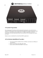
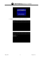
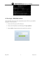
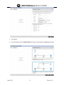
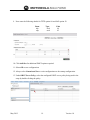
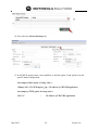
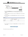
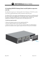
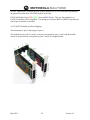
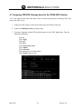
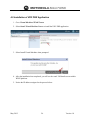
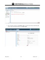
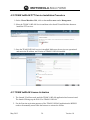
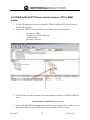
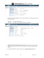
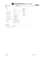
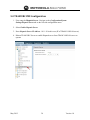
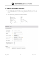
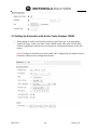
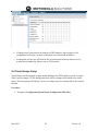
Motorola Solutions - Unified Retail Communications Installation/Configuration Guide Draft May 2012 1 Version 1.0 Contents 1.0 Overview................................................................................................................................... 3 2.0 Physical Characteristics ............................................................................................................ 3 3.0 System Preparation ................................................................................................................... 5 4.0 Lab System Installation Procedure ........................................................................................... 5 4.1 First Console Login............................................................................................................... 7 4.2 First Time IP Address Setup ................................................................................................. 8 4.3 First Login – WiNG Web Interface ...................................................................................... 9 4.4 Initial Setup Wizard ............................................................................................................ 10 4.5 DHCP Server Setup ............................................................................................................ 18 4.6 Installing FXO/FXS Gateway Board onto NX platform expansion card slot .................... 22 4.6.1 Sangoma A200 - FXO FXS Module Installation in NX Chassis..................................... 23 4.7 Assigning FXO/FXS Gateway board to the TEAM URC (Centro) ................................... 25 4.8 Installation of URC PBX Application ................................................................................ 26 4.9 Activate the URC Application (centro) .............................................................................. 27 4.10 TEAM VoWLAN PTT Service Installation Procedure .................................................... 30 4.11 TEAM VoWLAN License Activation .............................................................................. 30 4.12 TEAM VoWLAN PTT Server Activate License – FTP to WSM system ........................ 32 4.13 TEAM VoWLAN PTT Configuration.............................................................................. 34 5.0 TEAM URC PBX Configuration............................................................................................ 38 5.1 Add URC-EWP Handset Subscribers ................................................................................. 39 5.2 Setting Up Subscriber with Audio Codes Deskset 320HD................................................. 40 5.3 Subscriber Class of Service ................................................................................................ 41 5.4 Trunk Groups Setup ............................................................................................................ 42 5.5 Dial Plan Configuration ...................................................................................................... 45 5.6 Routing Rules...................................................................................................................... 46 5.7 Music On Hold.................................................................................................................... 47 May 2012 2 Version 1.0 Unified Retail Communications Installation/Configuration Methodology 1.0 Overview Motorola Solutions Unified Retail Communications (URC) voice platform combines many essential voice and wireless data technologies to enable customers with an all in one solution for wireless control, IP network services, Voice and PBX services as well as Motorola’s unique Radio Link Services (RLS) for Radio integration and embedded PTT functionality. The URC also offers an easy to configure next generation user interface for simplified use and navigation. 2.0 Physical Characteristics The URC appliance consists of a 2U, 19 inch rack mountable chassis that provides all network and communications connectivity via the front panel. The Chassis is known as the NX Chassis. The Common AvaaNX Models are: (see specs below for each model) NX4500 NX4524 – with 24 PoE Ethernet Ports NX6500 NX6524 – with 24 PoE Ethernet Ports May 2012 3 Version 1.0 24 Port PoE The URC voice appliance chassis comes in an NX4500 and NX6500 form factor either in POE (power over Ethernet) or non-POE configurations. The 24 port gigabit Ethernet switch provides power for APs as well as IP Phones that shall be connected to the system. 4 Port USB Ports Note: An Radio interface unit for RLS can be connected the USB port # 4 only. Note: Use to load Operating System 4 Port Expansion Slots Supports expansions slots for PSTN and Network interface connections such FXO (trunk Line), FXS (Station Line) and T1/E1 digital TDM trunk connections to the PSTN or other PBX systems. Integrated System LED Lights: 4 LEDs on the front for quick system check on operation status: System 1 System 2 Fan Temp May 2012 4 Version 1.0 3.0 System Preparation Once obtaining the NX platform and all its appropriate licensing, the system will need to be installed. The following procedure includes system installation and setup procedures from initial procurement of operating system and applications. The following procedure is for BETA systems only and customer purchased systems may be different as OS and applications shall be pre-loaded. Obtain the source installation file to load OS and WING Applications 4.0 Lab System Installation Procedure 1. Insert the appropriate installation file on a USB drive and inmsert into USB port 1 on the NX box. 2. Select F3 on startup to select Boot Drive Menu. 3. Select load from USB FLASH DRIVE on the menu May 2012 5 Version 1.0 4. Follow the screens for installation steps performed May 2012 6 Version 1.0 4.1 First Console Login Once the system has been installed. Connect the console serial port of the NX chassis. You will login for the first time and change the administrator password for security. 1. Login as admin/motorola 2. Change admin password May 2012 7 Version 1.0 4.2 First Time IP Address Setup 1. Type en (short for enable to get to command mode) 2. Type config to get to configuration mode 3. Type self - to configure the local machine 4. Type interface vlan 1 5. Type ip address 10.1.1.1/24 6. Type commit - to write changes to db 7. Type write mem - to save to startup config 8. Type exit May 2012 8 Version 1.0 4.3 First Login – WiNG Web Interface After the IP address has beenset in the command line interface.The New system shall be manageable via the web interface. 1. Connect to the NX system via IP web browser. 2. Connect to the NX platform via the following GUI. https://ipaddress/ 3. Login as admin with password previously created in the console set. May 2012 9 Version 1.0 4.4 Initial Setup Wizard Once you login to the URC platform via the web browser for the first time you will be prompted to use the initial setup wizard to help pre-configure the WING and network applications to be used on this installation. 1. Select Start Wizard 2. Once Logged in for the first time. Select Initial Setup Wizard (NX….) 3. Enter the System Information such as administrator password/location/Time Zone and Country Code Specification 4. Next Select Enable HTTP HTTPS Telnet or SSH for remote management access. May 2012 10 Version 1.0 5. Click Next 6. For the topology, Select Bridge Mode for Network functionality. Highlighted in blue May 2012 11 Version 1.0 7. Then Click Next. 8. Next Enter the LAN configuration for the NX system. 9. For this setup, the DHCP server will used and range applied as 10.1.1.100 to 10.1.1.150. 10. The WAN interface will not be used in this setup. Select Next to go to next screen. May 2012 12 Version 1.0 11. Select Add WLAN. 12. Enter the WLAN credentials as desired. In this example it is set to: May 2012 SSID = training2 WPA2 encryption with PSK Authentication Passcode = motorola 13 Version 1.0 13. Select OK. 14. Enter Next to save the WLAN configuration. 15. On the AP discpovery screen. Enter a hostname for the AP if desired. APs are auto discovery when pre-connected to the platform. May 2012 14 Version 1.0 16. Select Next 17. Enter the Date and Time details for the system. 18. Enter NTP configuration if used. May 2012 15 Version 1.0 19. Click Finish to save configuration 20. Review your configuration and edit as desired. May 2012 16 Version 1.0 21. This sets up the initial configuration for the WLAN and network parameters. May 2012 17 Version 1.0 4.5 DHCP Server Setup In order to utilize the DHCP services on the NX platform. The following steps will be needed to be accomplished on the DHCP server configuration on the URC NX platform. The following steps are sample configuration performed in lab. 1. Login to the CLI interface via putty or terminal emulation program. 2. Login as admin/password previously set in the initial setup of the system. 3. Enter the following commands to determine the MAC address of the URC PBX services and TEAM Mobile Extensions (PTT) service. For TEAM URC (PBX) = show virtual-machine configuration team-centro For TEAM Mobile Extensions (PTT) = show virtual configuration team-vowlan 4. Next using a web browser, Login to the WING GUI as admin/password. 5. To setup DHCP configuration. Select the 1– Configuration / 2- Services / 3 - DHCP Server Policy 6. Next select the default-vlan-1 DHCP Pool. 7. Click the Global Settings tab on the top menu to enter additional DHCP options. In this example the tftp (option 66) and the oap (option 43) will be used. The TFTP service will be used for IP desksets to download binary files and the oap option will be used for wireless handset binaries/configuration downloads. 8. Select ADD ROW to enter DHCP option details. May 2012 18 Version 1.0 9. Next enter the following details for TFTP option 66 and OAP option 43: Name tftp oap Type ascii ascii Code 66 43 10. Click Add Row for additional DHCP options required. 11. Select OK to save configurations 12. Always select Commit and Save to write configurations to the startup configuration. 13. Under DHCP Server Policy, select the configured DHCP server policy being used in the setup by double clicking the policy. May 2012 19 Version 1.0 14. Next select the Advanced Settings tab. 15. In the DHCP options values, select Add Row to add the option 43 and option 66 in this specific subnet configuration. An example of OAP option 43 string value = 1%https://10.1.1.21:5070/oap/sac_pkg - IP address of URC PBX application An example of TFTP option 66 string value = 10.1.1.21 May 2012 - IP Address of URC PBX Application 20 Version 1.0 16. Next Select Static Bindings tab to set a reserved static IP address for the URC application and TEAM VoWLAN service with their appropriate dedicated MAC addresses 17. Then select ADD to Enter the hardware address for the URC server. Previously obtained in CLI access. 18. Next Select ADD to Enter the TEAM VoWLAN hardware address. Previously obtained in CLI access. 19. After Configuration is complete, select Commit and Save to write changes to memory for future restarts. This concludes the setup of your DHCP server. May 2012 21 Version 1.0 4.6 Installing FXO/FXS Gateway Board onto NX platform expansion card slot The NX platform supports up to 4 add-on modules for such functions as FXO, FXS as well as T1/E1 Gateway termination boards for PSTN connection to the URC system. The Motorola URC system supports internal Sangoma gateway boards to be installed internally into the NX chassis 4 port expansion slots. The following example configuration will be based on istallation of Sangoma FXO/FXS A200 series combination gateway boards. The configuration will include 2 FXS (stations) and 2 FXO (trunks) ports for use. To install an expansion module: 1. Remove the expansion card cover for the expansion module bay. 2. Insert the expansion module into the expansion module bay. 3. Tighten the retention screws on the sides of the expansion module. The following figure represents the installation of the expansion module for the NX-4524 and NX-6524 models: May 2012 22 Version 1.0 4.6.1 Sangoma A200 - FXO FXS Module Installation in NX Chassis Slide the modules into the main board until you feel the modules click home properly. You should be able to read the designation FXO or FXS on the outside of the card (Remora) after installation. NB: If you should make a mistake and install the modules the wrong way round, the modules will not work, but they will not be damaged. Notes on Sangoma Boards: The Sangoma A200 card with FXS modules, or A200 cards connected via backplane bus, need much more power than a regular PCI bus can provide. In order for an FXS module or multiple cards to work properly, a 4 pin computer power cable must be plugged in to the main card itself. This is the same power cable, male connector, that one would connect to a hard driver or a cdrom. Any regular computer power supply should provide more than enough power, however for best and most reliable performance, bigger the power supply the better (eg: 450W) A SINGLE A200 with no Remora and only FXO modules (i.e.pnly 4 ports FXO) does not need to be connected to computer power supply! All other combinations DO, including any FXO combination that has more than 4 FXO ports! The external power cable should be used by default on all systems, if possible. FXO modules are RED in color FXS modules are GREEN in color An A200 Analog card can be outfitted with any combination of the two. All FXO or FXS or one May 2012 23 Version 1.0 of each. Furthermore, each RJ4 pin port is either mapped to FXO or FXS module depending on the physical location of the FXO/FXS module on the card. FXO/FXS Modules have RED/GREEN face and BLUE back. This way the installation of FXO/FSX modules will be simplified. The analog port will glow RED or GREEN depending on which type of modules is installed. 4.6.2 FXO/FXS Module and Ports Mapping The bottom port is port 1 and top port is port 4. The module closest to the 12v molex connector corresponds to ports 1 and 2 and the module closest to the pci brackets corresponds to ports 3 and 4. See diagram below. May 2012 24 Version 1.0 4.7 Assigning FXO/FXS Gateway board to the TEAM URC (Centro) Note: You will also notice that code name Centro is used in many aspectrs of naming. This is the same as the URC server. 1. Login to the NX chassis via the serial console port in the front of the unit. 2. Login in as admin/password previously setup 3. To setup a Sangoma Analog GW board and assign it to the URC Application. Type the following commands. Type en Type config Type self Type slot 1 Type assign team-centro Type commit Type write mem Type exit (get out of config mode) Type reload (restart server) May 2012 25 Version 1.0 4.8 Installation of URC PBX Application 1. Go to Virtual Machines/TEAM Centro. 2. Select Install Virtual Machine Button to install the URC PBX application. 3. Select Install Virtual Machine when prompted. 4. After the installation has completed, you will see the result VM details screen within WING platform. 5. Notice the IP address assigned to the process below. May 2012 26 Version 1.0 4.9 Activate the URC Application (centro) 1. Navigate to Virtual Machines/TEAM Centro, select Launch UI. 2. On the first launch, reset the admin password as desired. The password must include a Capital letter as well as a number. Example = Password1. May 2012 27 Version 1.0 3. Next, Select Apply. 4. Select System Configuration/Licensing 5. Select the appropriate License File to upload for activation. Then click Select File to browse to upload from PC. Note: License Obtained by Motorola support services or ordering services. 6. Click ACTIVATE on the bottom left to activate the URC application. May 2012 28 Version 1.0 7. Once Activated, navigate to the Statistics Tab on top menu, then click on the Health and System Tab to show that the URC is in activate state. May 2012 29 Version 1.0 4.10 TEAM VoWLAN PTT Service Installation Procedure 1. On the Virtual Machines Tab, click on the nx65xx menu under Management. 2. Select the TEAM VoWLAN Service and then select Install Virtual Machine button to install the PTT services. 3. Once the TEAM VoWLAN service is installed. Make sure the services are operational and notice the IP address, and Version of TEAM VoWLAN installed. 4.11 TEAM VoWLAN License Activation 1. The Launch UI will not work until the TEAM VoWLAN application has been activated. The launch UI brings up the Web UI to TEAM VoWLAN. 2. For the first time activation purposes of the TEAM VoWLAN application the WEBUI needs to be manually entered into the browser to activate the license. May 2012 30 Version 1.0 Sample = http:// TEAM VoWLAN IP Address/webui/WSMApp.html 3. Once the TEAM VoWLAN Web UI is launched properly, the login screen will appear. The default user account for TEAM VoWLAN will be: userID = admin password = motorola 4. It will then ask you to change the password for the admin account. 5. Next change the admin password. Password criteria must include a Capital Letter and at least one Number For example = Password1 May 2012 31 Version 1.0 4.12 TEAM VoWLAN PTT Server Activate License – FTP to WSM system 1. Use an FTP application or client to upload the TEAM VoWLAN PTT server license to the NX/URC platform. 2. Login to the TEAM VoWLAN/WSM server IP address previously assigned Using secure FTPs IP Address of TEAM VoWLAN userID =ftpuser password = ind3adn 3. FTP the license.sig and license.xml file into the following directory on TEAM VoWLAN Server: /usr/deployment/activation/wsm_lic directory 4. Once the TEAM VoWLAN application is activated, next navigate from a web browser in the TEAM VoWLAN Server GUI, to the Activate TEAM VoWLAN screen. May 2012 32 Version 1.0 Located within the Operations Tab/Device/Activate TEAM VoWLAN. 5. Enter the appropriate TEAM VoWLAN activation key information as provided by your license file. 6. Click Execute to activate the license. The Activation = Done should be applied if correct license file May 2012 33 Version 1.0 4.13 TEAM VoWLAN PTT Configuration 1. In the TEAM VoWLAN application. Some basic configuration is required to setup the WSM environment. 2. Login as admin, navigate to the Configuration Tab and Select WSM Policy to configure the system setup. 3. Then select System on the Configuration Menu. 4. Enter the following parameters as minimum configuration for initial setup. SIP Address of Record Domain Name: Dispatch Service: Group Call Service: Text Messaging: team.mot.com yes yes yes 5. Next select the External Services screen. 6. Enter the following parameters as minimum initial configuration. Primary AAA Server hostname: Primary AAA Server Port: May 2012 10.1.1.20 (WSM IP Address) 1812 (default) 34 Version 1.0 7. Navigate to the WLAN Handsets screen on the menu. Enter the following parameters for initial configuration: Time Zone: PBX Type: set to your local timezone “No PBX” (when using TEAM URC internal PBX) 8. Add TEAM VoWLAN Subscribers for PTT services. This will be done for wireless handsets that require PTT services for each subscriber. This will not be applied for IP desksets. 9. In the TEAM VoWLAN webUI, Navigate to the Configuration/Subscribers tab May 2012 35 Version 1.0 10. Click on “Add” on the lower right hand corner to add PTT subscribers. 11. Set the following subscriber parameters to setup mobile extensions for PTT TEAM VoWLAN services. This is required for EWP and Motorola Handsets that require PTT services. User ID: Password: Enterprise Extension: Associates Name: Text Messaging Service Call Forwarding Service Sim Ringing Service FMC Mode Dispatch Service Emergency Call Service Group Call Service Talk Groups: 3000 pass 3000 xxxxxxxxxx Active Active Active VoWLAN Mode (wifi only device) Active Active Active 1 12. Once configured, click OK to save your subscriber configuration. The subscribers that you created will now be listed under the Configuration/Subscribers list. May 2012 36 Version 1.0 May 2012 37 Version 1.0 5.0 TEAM URC PBX Configuration 1. First setup the Dispatch Server. Navigate to the Configuration/System Settings/Dispatch Server tab on the left side configuration menu. 2. Select Enable Dispatch Server 3. Enter Dispatch Server IP Address: 10.1.1.20 in this case (IP of TEAM VoWLAN server) 4. Reboot TEAM URC Server to enable Dispatch server from TEAM VoWLAN server to operate May 2012 38 Version 1.0 5.1 Add URC-EWP Handset Subscribers 1. For each subscriber within the URC system, a subscriber will need to be created. For each TEAM VoWLAN user as well as analog and SIP based desksets will need to be created. 2. Enter the following parameters for each user subscriber: Extension: Extension Type: Name: Class of Service: SIP Phone Type: Codecs: Register with Centro: May 2012 3500 SIP user name Class 00 Motorola EWP G729, uLaw (G711) yes 39 Version 1.0 5.2 Setting Up Subscriber with Audio Codes Deskset 320HD 1. When adding an audio codes DeskSet, make sure the Phone type is the appropriate AudioCodes type, in this case Audio Codes 320HD model. Also make sure the MAC address is populated so that the set can download its configuration binaries on the first reboot. Note: if changes to the deskset are made within URC configuration, the handset must be rebooted to obtain its new configuration binaries. May 2012 40 Version 1.0 5.3 Subscriber Class of Service 1. For each subscriber on the system a default Class of Service 00. There are 11 CoS groups available in the URC configuration server. 2. Navigate to Subscribers configuration screen. 3. Set the configuration for the Class of Service to Class00. 4. Next select the Subscribers/Service Class/Class of Service. 5. Select the Class00 and enable the appropriate CoS features that you want to enable for the subscribers. May 2012 41 Version 1.0 6. If changes have been made to the deskset or EWP handsets, and a change of CoS configuration will require a reboot of the phone set to download its binaries. 7. On the phone set, the user will then be able to activate/deactivate the feature service, weather this is handled by feature code or TUI interface. 5.4 Trunk Groups Setup Trunk Groups will be required to setup outside dialing to the PSTN public network or central office. In this example, 2 FXO analog trunk lines will be configured and added to the trunk group. The trunk group will bind the 2 access as a single entity for routing calls to the external network. Procedure: 1. Navigate to Configuration/System/Trunk Configuration/FXO Lines. May 2012 42 Version 1.0 2. For each FXO line that is assigned to the URC server configuration, a phone number will need to be assigned to the physical trunk port. In this example, the FXO channel 3 and 4 are being used and allocated to the PBX system. 3. Select the each FXO line to be used in this trunk group and enter a unique phone number for each line needed. This number will be used for incoming routing as well as DN identification of that analog trunk line. 4. Next select Trunk Groups under System Configuration tab 5. Select ADD on the lower right hand corner of the Trunk Groups screen to create the trunk group for these FXO lines. 6. Enter the Trunk Group Name: May 2012 43 Version 1.0 7. Add the FXO trunk priorities to route calls on this 8. Click OK to save the configuration of this trunk group. May 2012 44 Version 1.0 5.5 Dial Plan Configuration The Dial Plan is used to configure the telephone number ranges to be supported by Centro. Each number range tells Centro whether or not to take calls made to phone numbers lying within the defined Number Range. If a dialed or received telephone number does not lie within a Number Range, Centro will not know how to handle the call, and the call will fail. Centro supports three types of number ranges: PSTN: This Type identifies number ranges which pertain to outgoing calls to the PSTN. Public: This Type identifies number ranges which apply to incoming calls. This is usually the range of publically routable numbers which have been allocated to the enterprise by the public Telco provider. 1. To configure the Extension Dial Plan click on “Configuration”, “System”, then expand “System Configuration”. 2. Select Dial Plan and click “Add”. 3. Fill in the following parameters: a. Description: Outbound ten digit dialing Type: pstn b. Number Range: [2-9]XXXXXXXXX c. Prefix: 9 (represents dialing 9 to get an outside line) May 2012 45 Version 1.0 4. Click “OK” when finished. Notice the Navigation window now contains another frame. The green plus sign and the red minus sign on the bottom allow you to add and delete dial plans. 5.6 Routing Rules 1. A routing rule will map the dial patterns to the the appropriate trunk group for call routing purposes. In this example, the long distance dial pattern will be associated to a Route Rule as well as the Trunk Group used for these call routes. 2. Enter the following parameters: Route Name: Outbound Dial Rule Dial Pattern Rule: Long Distance - previously created Trunk Group: AnalogTG – previously created May 2012 46 Version 1.0 3. OK to save the configuration. If correctly configured, this will allow for 11 digit calls to be sent out the AnalogTG which includes 2 FXO ports for 2 simultaneous calls to be made out this new trunk group. 5.7 Music On Hold The URC PBX server will provide Music on Hold functionality. When a user goes on hold, the wav file that is uploaded to the server will be played to the on-hold user. Procedure: 1. A wav audio file must be created or existing the following format = PCM, 8KHz, 16 bit, mono. If the file is not in the correct format, the on hold music will not play. 2. To upload the MoH file, navigate to the Configuration/System/MOH Configuration. May 2012 47 Version 1.0 3. Click Add to upload a wav file to the URC server. 4. Click on the Select File Button to browse and upload a wav file from your PC/Laptop. For feature configuration refer to the Centro_Configuration_Menu_Guide_v1.5_WING document. May 2012 48 Version 1.0