1
sockets and rocker faces and pressed-in bronze
bearings.
They are drilled -for lubrication.
Pushrods are constructed of steel tubes and pressedin, hardened, forged steel ball ends, which are
center drilled for oil passages. The pushrod
housings are beaded steel tubes. The bead at the
cylinder end retains a packing ring between two
washers. The bead at the crankcase end retains a
heavy spring, washer, packing ring and second
washer.
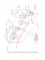
2-10. FUNCTIONAL SYSTEMS.
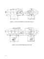
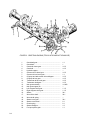
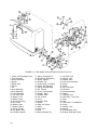
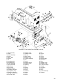
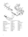
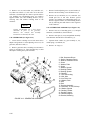
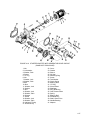
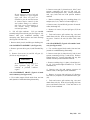
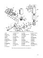
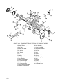
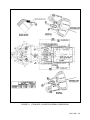
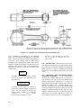
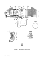
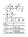
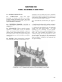
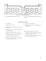
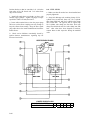
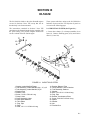
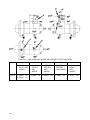
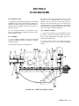
2-11. GEAR TRAIN- SANDCAST CRANKCASE (See Figure 2-2). When starting the engine,
torque is transmitted from the starter (16) through
adapter components (17 through 22) to crankshaft
gear (1). As wormwheel (20) is turned, spring
mounted on its hub is tightened to grip knurled
drum of shaftgear (22). This design eliminates
wear and stress encountered in direct drive starter
systems. After engine is started, spring returns to
its normal position, thus disengaging starter. The
shaftgear (22) is now used to transmit torque from
the crankshaft gear to the generator drive pulley
(16, Figure 4-16).
a. Torque from the crankshaft (2) is transmitted by
the crankshaft gear (1) directly to the idler gear (12)
and camshaft gear (3).
b. The idler gear, rotating in a counterclockwise
direction, drives magneto drive gears (14 and 15).
Optional accessories mounted on crankcase upper
rear are driven by internal splines of magneto drive
gears.
c. The fuel pump drive gear is driven by the
camshaft cluster gear. The splined end of the oil
pump and tachometer drive gear (8) mates with
internal splines of the camshaft gear and transmits
torque to the oil pump driven gear (9) and the
tachometer drive gear (10). The governor drive
bevel gear (6) on the front of the camshaft drives
the governor driven bevel gear (7).
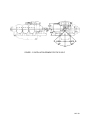
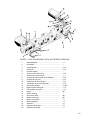
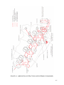
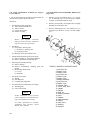
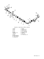
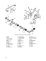
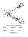
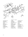
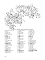
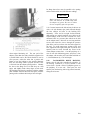
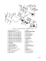
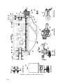
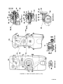
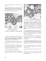
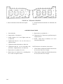
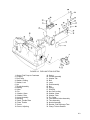
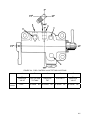
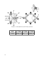
2-12. GEAR TRAIN -PERMOLD CRANKCASE
(See Figure 2-3).
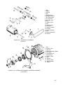
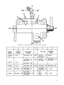
a. When starting engine, torque is transmitted from
the starter (15) through adapter components (16
through 20) to crankshaft gear (1). As worm-wheel
(19) is turned, spring mounted on its hub is
tightened to grip knurled drum of shaftgear (20).
After engine is started, spring returns to its normal
position, thus disengaging starter.
Torque is
transmitted to the alternator by a face gear (23)
mounted on the crankshaft.
b. Torque from the crankshaft (2) is transmitted by
the crankshaft gear (1) directly to the idler gear (12)
and the camshaft gear (3).
c. The idler gear, rotating in a counterclockwise
direction, drives the magneto drive gears (13, 14).
Optional accessories mounted on the crankcase
upper rear are driven by internal splines of magneto
drive gears.
d. The fuel pump coupling is driven directly from
the crankshaft gear (1). The splined end of the oil
pump and tachometer drive gear (8) mates with the
internal splines of the camshaft gear and transmits
torque to the oil pump driven gear (9) and the
tachometer drive gear (11). The governor drive
bevel gear (6) is keyed to the camshaft (4) and
meshes with and drives the governor driven bevel
gear (7).
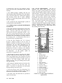
2-13.
LUBRICATION
SYSTEM
SANDCAST CRANKCASE.
FOR
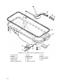
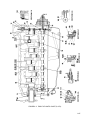
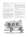
a. The engine driven, gear type oil pump draws oil
from the sump through the oil suction tube and
crankcase oil passage. From the gear chamber oil is
directed to the oil filter chamber and to the
tachometer drive gear. A filter by-pass valve is
incorporated in the pump housing in the event that
the filter becomes clogged.
b. After leaving the pump oil is directed through
passages to the right crankcase oil gallery. Right
side lifters, guides and valve mechanisms are
lubricated by passages leading off this gallery. An
oil temperature control valve is located at the front
end of the right gallery to regulate oil temperature
within specific limits.
When oil reaches a
temperature high enough to require cooling, the oil
temperature control valve expands and blocks
passage, directing oil to the oil cooler. From the oil
temperature control valve cavity oil is directed to
the camshaft passage. A groove around the front of
the camshaft directs oil to the front camshaft
bearing and left crankcase oil gallery .
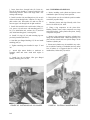
c. Lubricating oil is directed to the governor drive
gear and the propeller governor through pass- ages
off the left main gallery. Oil is channeled through a
discharge port to the crankshaft oil transfer collar,
which directs it to the crankshaft interior.
2-3