1
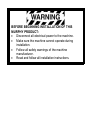
PowerView Model PV101-C User’s Guide Version 3.2 2013-04-08 00-02-0796 Catalog Section 78 Table of Contents Introduction ............................................................................... 1 Engine and Transmission Parameters .................................................................... 2 Faceplate Features ................................................................................................. 3 Navigation and Keypad Functions .......................................................................... 4 First Time Start Up ................................................................... 8 Main Menu Options ................................................................11 Go to 1-Up Display/Go to 4-Up Display ................................................................ 11 DPF Regen* .......................................................................................................... 11 Selecting a Language ........................................................................................... 13 Stored Codes ........................................................................................................ 14 Engine Configuration............................................................................................. 14 Setup 1-Up Display ............................................................................................... 14 Setup 4-Up Display ............................................................................................... 17 Service Reminders ................................................................................................ 20 Select Units ........................................................................................................... 22 Backlight Adjustment ............................................................................................. 22 Contrast Adjustment .............................................................................................. 22 Utilities Menu ..........................................................................23 Gage Data ............................................................................................................. 23 Remove All Gages ................................................................................................ 23 Software Version ................................................................................................... 23 Fault Conversion ................................................................................................... 24 Analog Input .......................................................................................................... 25 Engine Speed Control ........................................................................................... 25 OEM Menu ...............................................................................27 MODBUS Setup ................................................................................................. 27 CANBUS Data Rate .............................................................................................. 28 Select Engine ECU ............................................................................................... 29 Set Source Address .............................................................................................. 30 Restore All Defaults .............................................................................................. 30 Clear Machine Hours ............................................................................................ 30 Set Machine Hours ................................................................................................ 30 Fuel Setpoints ....................................................................................................... 31 DPF Regen Menu ON/OFF ................................................................................... 31 ENG SPD CTRL Menu ON/OFF ........................................................................... 32 Faults and Warnings..............................................................33 Auxiliary Gage Fault .............................................................................................. 34 Active Fault Codes ................................................................................................ 34 Derate / Shutdown Codes ..................................................................................... 35 Acknowledging Fault Codes ................................................................................. 36 Troubleshooting .....................................................................37 Additional Contact Information ...........................................42 In order to consistently bring you the highest quality, full featured products, we reserve the right to change our specifications and designs at any time. The latest version of this manual can be found at www.fwmurphy.com. Warranty - A limited warranty on materials and workmanship is given with this Enovation Controls product. A copy of the warranty may be viewed or printed by going to www.fwmurphy.com/warranty BEFORE BEGINNING INSTALLATION OF THIS MURPHY PRODUCT: • Disconnect all electrical power to the machine. • Make sure the machine cannot operate during installation. • Follow all safety warnings of the machine manufacturer. • Read and follow all installation instructions. Introduction Congratulations on purchasing your PowerView display, a multifunction tool that provides a window into the many parameters and service codes of modern electronic engines and transmissions. This guide is intended to help you set up your PowerView display and identify navigation basics and product features. The display’s simple navigation and powerful features allow you to quickly master the product. Additional information can be found on our website at www.fwmurphy.com/pv101/. 00-02-0796 -1- 2013-04-08 Engine and Transmission Parameters The following are some of the engine and transmission parameters which can be displayed in standard or metric units as well as in English, Spanish, French, Italian or German languages (when applicable, consult engine or transmission manufacturer for SAE J1939 supported parameters): • • • • • • • • • • Engine RPM Engine hours System voltage Percent engine load at current RPM Coolant temperature Oil pressure Fuel economy Throttle position Engine manifold air temperature Current fuel consumption 00-02-0796 -2- • • • • • • Transmission oil pressure Transmission oil temperature Transmission gear position Engine configuration parameters Active fault codes Stored fault codes 2013-04-08 Faceplate Features 00-02-0796 -3- 2013-04-08 Navigation and Keypad Functions The keypad on the PowerView display is a capacitive touch sensing system. There are no mechanical switches to wear or stick. The keys on the keypad perform the following functions: Menu – Enter or exit menu screens. Left Arrow – Scroll the screen or move the parameter selection to the left or upward. Right Arrow – Scroll the screen and move the parameter selection to the right or downward. Enter Key – Select a menu or parameter or hide/view an active fault code. 00-02-0796 -4- 2013-04-08 Basic Navigation 1. When Menu is pressed, the Main menu items display. 2. Press the Arrow Keys to move the selection bar to other menu items. 00-02-0796 -5- 2013-04-08 3. Certain menus have multiple pages. Scrolling to the top or bottom item on the current page reveals other menu items on additional pages. 00-02-0796 -6- 2013-04-08 4. When the desired item is highlighted by the cursor, pressing Enter selects that item and displays the corresponding screen. 00-02-0796 -7- 2013-04-08 1. First Time Start Up When power is first applied to the display, the Murphy logo is displayed. NOTE: Expect a 20-minute warm up for the display at temperatures of -29oC/-20oF. 00-02-0796 -8- 2013-04-08 2. If the Engine ECU is broadcasting a ‘Wait to Start' message, this screen will be shown. Engine manufacturers typically recommend against starting the engine while this message is broadcasted from the ECU. Once the ECU stops broadcasting this message, this screen will no longer be displayed. 00-02-0796 -9- 2013-04-08 3. Once the engine has started, the single engine parameter is displayed with the engine RPM. Touching the Right Arrow Key displays the coolant temperature. The screen can be changed to other parameters by touching Menu. 00-02-0796 - 10 - 2013-04-08 Main Menu Options This section describes the features listed on the Main menu of the PowerView. These menu options display whenever you touch Menu. The Arrow Keys allow you to scroll through items. Enter selects the highlighted option. Go to 1-Up Display/Go to 4-Up Display If you want to go to a different display, touch Enter. The alternate view is displayed. DPF Regen* *Murphy products are compliant with requirements for U.S. EPA Emission Standard ‒ Tier 4 Interim and EU Emissions Standard ‒ Stage IIIB for diesel engines. These engines when fitted with a DPF (Diesel Particulate Filter) can self-clean the filter of particulates. This self-cleaning is known as Regeneration. PowerView offers 3-CAN options when DPF REGEN is enabled and available in the engine ECU. For more information, find document # 1110836 on the Murphy Web site (www.fwmurphy.com). Unless selected in the OEM Menu, DPF REGEN does not display in the Main Menu. When available, the following options are presented: 00-02-0796 - 11 - 2013-04-08 1. AUTO DPF REGEN – This is the factory default. Select and PowerView sends a CAN message to the ECU to perform DPF Regeneration (regen) automatically whenever needed. 2. REQUEST DPF REGEN – Select this and a second screen, REQUEST DIESEL PARTICULATE FILTER REGEN, displays. Use this to force a regen when autoregen is not due or is inhibited by PowerView. Touch YES (Enter) and PowerView sends a request for a regen every second for 10 seconds. If the engine does not respond, PowerView defaults back to Auto DPF Regen. You may send the request again or exit without sending a request by touching CANCEL (Menu). You return to the Main menu. 3. INHIBIT DPF REGEN – In cases where regen cannot be performed due to restrictions, select this to eliminate the possibility of a regen occurring. The inhibit lamp displays when the engine ECU responds to this inhibit request from PowerView. Once this option is selected, it remains in place through power cycles. When inhibit is no longer needed, you can select a different option. 00-02-0796 - 12 - 2013-04-08 The following ISO symbols indicate regen status. In each case, the symbol displays when the parameter’s lamp status is broadcast from the ECU back to the PowerView. DPF Regen ISO Symbols Icon PGN SPN Description 64892 3697 High Exhaust Temperature (HEST) lamp indicates regeneration in process. 64892 3703 DPF Particulate Filter Restricted lamp indicates a Regen is needed. 64892 3698 DPF Inhibit lamp indicates an inhibited Regen status. Selecting a Language From LANGUAGES, you may select ENGLISH, ESPANOL, FRANCAIS, ITALIANO, or DEUTSCH. An asterisk to the right of the language indicates it is selected. 00-02-0796 - 13 - 2013-04-08 Stored Codes Select this and PowerView requests and displays stored fault codes from the engine ECU. If the engine does not support this function, a “Timeout ECU Not Responding” message displays. Engine Configuration This allows you to scroll through and view the engine’s configuration data. If the engine does not support this function, a “No Engine Configuration Data” message displays. Setup 1-Up Display Press Menu and use the Arrow Keys to highlight SETUP 1-UP DISPLAY, then press Enter. Three options are available for modification of the 1-Up display: 1. Use Defaults – This option contains a set of engine parameters: Engine Hours, Engine RPM, System Voltage, Battery Voltage, % Engine Load at Current RPM, Coolant Temperature, and Oil Pressure. 00-02-0796 - 14 - 2013-04-08 To select USE DEFAULTS, highlight the option and press Enter. A message indicating “RESTORED TO DEFAULTS” is displayed. 2. Custom Setup – In this option, select the parameters and order in which they will be displayed. The list is long; continue to scroll until you have seen all available parameters. To select Custom Setup, highlight and press Enter. A list of engine parameters displays. NOTE: The PV101 must see the parameter being broadcast over J1939 in order to select the parameter from the list. To select a parameter, use the Arrow Keys to scroll and highlight the parameter, then press Enter. Selected parameters are indicated by a number to the right of it. The numbers represent the order in which the parameters will be displayed. To deselect a parameter and remove it from the list of displayed parameters, highlight the parameter and touch Enter. 00-02-0796 - 15 - 2013-04-08 Continue to scroll and select additional parameters for the CUSTOM 1-UP DISPLAY. Touch Menu at any time to return to the CUSTOM SETUP menu. 3. Automatic Scan – (Default is OFF) Selecting the AUTOMATIC SCAN ON function will cause the 1-up display to scroll through the selected set of parameters one at a time. Once the Use Defaults, Custom Setup and Automatic Scan functions have been set, touch Menu once to return to the Main menu, or twice to display the 1-up display screen. 00-02-0796 - 16 - 2013-04-08 Setup 4-Up Display There are two 4-up display screens available. Each option can place parameter data into one of four areas on the screen known as quadrants. ▪ Factory defaults for the first 4-up display include coolant temperature, engine speed, oil pressure, and battery voltage. ▪ Factory defaults for the second 4-up display include DEF (diesel exhaust fluid) Level, DPF (diesel particulate filter) active regen status, exhaust filter inlet temperature, and exhaust filter outlet temperature. You can customize each 4-up display with the parameter you define for each quadrant. 1. Touch Menu and use the Arrow Keys to highlight SETUP 4-UP DISPLAY, and touch Enter. 2. To select USE DEFAULTS, highlight the option and press Enter. A message indicating “RESTORED TO DEFAULTS” is displayed. 3. To select CUSTOM SETUP, highlight the option and press Enter. The 4-up display appears. 00-02-0796 - 17 - 2013-04-08 4. Use the Arrow Keys to switch between the two 4-up displays. 5. To edit a 4-up display, touch Enter while that 4-up displays on screen. 6. Use the Arrow Keys to select which quadrant to edit. 7. Once you select a quadrant, press Enter and you move to a list of parameters. NOTE: The PowerView must see the parameter being broadcast over J1939 in order to select the parameter from the list. 8. The parameter highlighted is the selected parameter for the screen. The number to the right of the parameter indicates in which quadrant it displays. 00-02-0796 - 18 - 2013-04-08 1 = upper left quadrant 3 = upper right quadrant 2 = lower left quadrant 4 = lower right quadrant 9. Use the Arrow Keys to highlight the new parameter to be placed in the selected quadrant. Touch Enter. 10. Press Menu to return to the SETUP 4-UP CUSTOM SETUP screen. 11. The parameter in the selected quadrant has changed to the parameter selected in the previous screen. 12. Repeat the parameter selection process until you fill all quadrants. 00-02-0796 - 19 - 2013-04-08 Service Reminders SERVICE REMINDERS permit you to RESET REMINDERS or MODIFY REMINDERS for changing engine oil, air filters, and hydraulic oil or for servicing the engine and/or machine. NOTE: Service Reminders are internal reminders within PowerView. Once a Service Reminder is active, warnings will show SPN 916 and FMI 17. Check PowerView Service Reminders prior to calling Technical Support. 1. Use the Arrow Keys to highlight Service Reminders and touch Enter. 2. The Service Reminders options display. Use the Arrow Keys to select either Reset Reminders or Modify Reminders, and then touch Enter. 3. If you select Reset Reminders, use the Arrow Keys to highlight the Reminder you wish to edit. Touch Enter. 4. The Reminder name appears at the top of the screen. The action (ON or OFF) displays mid-screen, and two choices display at screen bottom. Touch Menu to Cancel the action. Touch Enter to choose Reset. 00-02-0796 - 20 - 2013-04-08 5. If you select Modify Reminders, use the Arrow Keys to highlight the Reminder to modify and touch Enter. 6. The Reminder name appears at top screen. The hour value displays mid-screen and allows you to set the number of hours to elapse before a Reminder prompts. Bottom screen shows Cancel and Save. Touch Cancel to discard changes and return to Reminders list. 7. Use the right Arrow Key to increment the highlighted number. Use the left Arrow Key to move to the next number space. 8. Touch Save. The Modify Service Reminder screen displays. Touch YES to save or NO to return to the Reminders list. 9. A modified Reminder displays a (+) at right of Reminder name when successfully completed. Follow the above steps to modify other Reminders. When finished, touch Menu to return to the Main Menu. 00-02-0796 - 21 - 2013-04-08 Select Units From SELECT UNITS, you may select how information is displayed: ▪ ENGLISH for Imperial units (PSI, °F) ▪ METRIC KPA ▪ METRIC BAR for IS units (kPa, Bar, °C). Backlight Adjustment ADJUST BACKLIGHT – Use the Arrow Keys to brighten or darken the backlight intensity. Contrast Adjustment ADJUST CONTRAST – Use the Arrow Keys to lighten or darken the text and graphics. 00-02-0796 - 22 - 2013-04-08 Utilities Menu UTILITIES is the last item on the Main Menu. The Utilities menu provides troubleshooting features and other information about the PowerView configuration. Gage Data View data for optional connected PVA gages. When Slave Active is enabled, gage data is not available. Remove All Gages Reset the gage memory on the PowerView. When Slave Active is enabled, this function is not available. Software Version This screen lists Configuration, Firmware, Languages, and Bootloader versions for this PowerView unit. You may need this information if requesting assistance from Technical Support. 00-02-0796 - 23 - 2013-04-08 Fault Conversion View/Edit the J1939 fault code version. Use the Arrow Keys to move between Versions, and then touch Enter to select a version. NOTE: There are four methods for converting fault codes. The PowerView always looks for J1939-Version 4. However, PowerView can be set to read one of three other J1939 versions, if Version 4 is not used/unavailable. Most ECU’s use Version 4, so adjustment of this menu option is rarely required. Upon receiving an unrecognizable fault, change to a different J1939 Version in the list. If the fault SPN does not change when the version is changed, the ECU generating the fault is using Fault Conversion Method 4. If the SPN number does change, but is still unrecognizable, try changing to another unused J1939 Version and continue to check the SPN number. 00-02-0796 - 24 - 2013-04-08 Analog Input With Analog Input highlighted, press Enter. You can select between two settings: 1) BACKLIGHT DIMMER, this is in factory default upon first use. The unit accepts an optional backlighting dimmer (0-1k Ω potentiometer). 2) FUEL LEVEL, touch Enter to reach SET LOW FUEL LEVEL screen. Then, touch Enter to reach LOW FUEL % screen. Use the right Arrow Key to increase, and left Arrow Key to decrease the percentage of remaining fuel at which to send a warning. The default is 20%. NOTE: The PowerView accepts optional Murphy fuel sender (recommend Model ES2F) for fuel level information. A custom setup for a non-Murphy fuel sender is available. For more information, see FUEL SETPOINTS, page 31 (OEM Menu). Engine Speed Control This option must be ON in the OEM Menu for functionality to be available from the Utilities Menu. 00-02-0796 - 25 - 2013-04-08 1) From the Engine Speed Control screen, touch Enter to reach the Speed Control screen. 2) To change the setting of the engine speed via TSC1; use the right Arrow Key to increase or left Arrow key to decrease the throttle setting. 3) Once the target speed is reached, select ENABLE (Enter) to turn ON the TSC1 throttling control. (Use Disable to turn throttling control OFF and discard changes). NOTE: Once enabled Engine Speed Control will stay enabled even through power cycles. To turn OFF, you must disable the feature from the SPEED CTRL screen. 00-02-0796 - 26 - 2013-04-08 OEM Menu The OEM menu is the last item on the Utilities menu. You must have a password to access the OEM menu. Once in the OEM Menu, select an item by highlighting it and touch Enter to reach additional screens. ENTER PASSWORD screen – Enter 3482 in the numeric spaces provided. Start at the furthest left numeric value and use the Left Arrow Key to increment the number and the Right Arrow Key to move to the next numeric position. If the Murphy standard key does not work, contact the OEM from whom the engine or machine was purchased. If you have access, the password is user changeable via the PV101-C Config Tool application. The following items are in the OEM Menu. MODBUS Setup To set the MODBUS, highlight MODBUS SETUP and touch Enter. 00-02-0796 - 27 - 2013-04-08 1) There are four selections: Use Factory Defaults, Serial Port Setup, Slave Address Setup, and Master Active/Slave Active. You can toggle between Slave Active (which is SCADA/remote Modbus master) and Master Active (which is Auxiliary gages). Highlight your selection and touch Enter. 2) If in Slave Active, select SERIAL PORT SETUP and touch Enter. 3) Scroll through the Serial Port Setup list and make selections for BAUD RATE, PARITY, DATA BITS, and STOP BITS to configure the serial port parameters for your Modbus slave application. CANBUS Data Rate Touch Enter to reach the six CANBUS data rates. Use the Arrow Keys to highlight your choice and touch Enter to make the selection. 00-02-0796 - 28 - 2013-04-08 Select Engine ECU Highlight Select Engine ECU and touch Enter. 1) The message “LISTEN TO ECU: ALL” displays as the default setting. This message indicates the PV101 is listening to all devices on the network. 2) To change the setting to a specific address, press the Arrow Keys to scroll through the selections (0253, and ALL). 3) Once the target address displays, press Enter. 4) A confirmation screen displays; selecting NO (Menu) returns to the SELECT ENGINE ECU screen. Selecting YES (Enter) stores the selected address and returns to the OEM menu. 00-02-0796 - 29 - 2013-04-08 Set Source Address Allows setting the source claim address for the PowerView on the CAN Network. Options are Auto Claim or 0 to 253. Restore All Defaults PowerView automatically resets after the restore defaults is complete. RESTORING ALL FACTORY DEFAULTS displays when this is selected. Clear Machine Hours Use this to clear machine hours internal to PowerView outside of ECU hours. Set Machine Hours Machine hours calculate internally when the RPM is greater than 50 and the engine is not broadcasting hours. Use this if you want to track hours for just the machine. 00-02-0796 - 30 - 2013-04-08 Fuel Setpoints Highlight and press Enter to select Fuel Setpoints. 1) Press Enter to turn Fuel Setpoints ON or OFF. 2) Choose Set Empty Setpoint, Set Fuel Setpoint, Show Fuel Setpoints, Clear Fuel Setpoints, or choose to set ¼, ½ and ¾ fuel points. Fuel Setpoints must be ON to work with a non-Murphy fuel sender. Modifying fuel setpoints is a complex process. To configure for a Murphy Fuel Sender or program for a nonMurphy Sender, find document #1110833, PowerView – Model PV101-C V3.2 Fuel Sender Calibration on the FW Murphy Web site at www.fwmurphy.com/pv101. DPF Regen Menu ON/OFF Highlight and touch Enter to turn this option ON or OFF. Turn this option ON to have it available in the Main menu or OFF for no availability in the Main menu. 00-02-0796 - 31 - 2013-04-08 ENG SPD CTRL Menu ON/OFF This option must be ON in the OEM Menu for functionality to be available in the Utilities Menu. Highlight and touch Enter. The Speed Control can be Enabled (ON) or Disabled (OFF). 00-02-0796 - 32 - 2013-04-08 Faults and Warnings The PowerView provides two means for detecting faults and warnings: visual LEDs on the casing (Amber in the upper left corner, and Red in the upper right corner) and fault indicators on the display. Visual Indication • Amber LED (Warning) • Red LED (Derate / Shutdown) Fault Indicators 00-02-0796 - 33 - 2013-04-08 Auxiliary Gage Fault Murphy PVA Gages can be attached to the PowerView. If an auxiliary gage should fail, the 1-up or 4-up display will be replaced with a fault message: GAGE NOT RESPONDING. NOTE: A fault can only be cleared by correcting the cause of the condition (See Troubleshooting in this document). Active Fault Codes When the PowerView receives a fault code from an engine, the 1-up or 4-up display is replaced with the active fault codes message. See following fault example: 00-02-0796 - 34 - 2013-04-08 Example: Active Fault Code screen Derate / Shutdown Codes When the PowerView receives a severe fault code from an engine control unit the 1-up or 4-up display is replaced with the SHUTDOWN message. 00-02-0796 - 35 - 2013-04-08 Acknowledging Fault Codes 1. To acknowledge and hide the fault and return to the 1-up or 4-up display, touch Enter. The display will return to the 1-up or 4-up display, but the display will contain the warning or shutdown icon. 2. Touch Enter to redisplay the hidden fault. Touch Enter once again hides the fault and returns the screen to the 1-up or 4-up display. 00-02-0796 - 36 - 2013-04-08 Troubleshooting WAIT TO START PREHEATING is displayed The ECU is broadcasting a 'Wait to Start' message. Engine manufacturers typically recommend against starting the engine while the ECU is broadcasting this message. Once the ECU stops broadcasting this message, this screen will no longer be displayed on the PowerView. CANBUS FAILURE is displayed The PowerView has not received any valid J1939 CAN messages for at least 30 seconds. Check wiring, CANBUS, termination resistors, and Engine ECU address in the OEM Menu. TIMEOUT ECU NOT RESPONDING is displayed The PowerView sent a request to the ECU for Stored Fault Code (DM2) information, and the ECU did not respond to the request. This message on the PowerView indicates the ECU may not support Stored Fault Code (DM2) functionality over J1939. 00-02-0796 - 37 - 2013-04-08 NO STORED CODES is displayed The PowerView sent a request to the ECU for Stored Fault Code (DM2) information. The ECU responded: There are zero stored codes. NO GAGE DATA is displayed The PowerView has no record of gages connected to the RS485 bus. NO DATA is displayed in place of a parameter value The PowerView has not received data for the selected parameter for at least 5 seconds. NOT SUPPORTED is displayed in place of a parameter value This means the data received for this parameter is not valid or not supported. 00-02-0796 - 38 - 2013-04-08 DATA ERROR is displayed in place of a parameter value The ECU is sending a message that there is a data error with this parameter. Alternatively, (PV101 only) FUEL LEVEL has been selected for display, ANALOG INPUT has been set to FUEL LEVEL, but no Murphy Fuel Sender has been connected to the analog input. One of the 4-UP quadrants is empty No parameter has been selected for display in this quadrant. Display is not readable, either very dim or very dark The LCD contrast may have been over or under adjusted. Press and hold the MENU key for approximately 5 seconds. This will reset the LCD contrast setting to factory default. PVA Gages not working When PVA Gages are connected and do not seem to work, go to the Utilities menu and select Remove all Gages. 00-02-0796 - 39 - 2013-04-08 IMPORTANT! Before returning your PV101 for Warranty, please call our Technical Support team to further troubleshoot any issues. +1 (918) 317-4100 00-02-0796 - 40 - 2013-04-08 NOTES 00-02-0796 - 41 - 2013-04-08 NOTES NOTES Murphy, the Murphy logo, and PowerView are registered and/or common law trademarks of Enovation Controls, LLC. This document, including textual matter and illustrations, is copyright protected by Enovation Controls, with all rights reserved. © 2013 Enovation Controls, LLC. Other third party product or trade names referenced herein are the property of their respective owners and are used for identification purposes only. Additional Contact Information ENOVATION CONTROLS – CORPORATE HQ ENOVATION CONTROLS – SAN ANTONIO OFFICE FW MURPHY, LTD. MURPHY ECONTROLS TECHNOLOGIES (HANGZHOU) CO, LTD. 5311 S. 122nd East Ave. Tulsa, OK 74146 USA Phone: +1 918 317 4100 FAX: +1 918 317 4266 [email protected] Web: www.fwmurphy.com Church Rd Laverstock Salisbury SP1 1QZ UK Phone: +44 1722 410055 FAX: +44 1722 410088 [email protected] Web: www.fwmurphy.co.uk 5757 Farinon Drive San Antonio, TX 78249 USA Phone: +1 210 495 9772 FAX: +1 210 495 9791 [email protected] Web: www.econtrols.com 77 23RD Street Hangzhou Economic & Technological Development Area Hangzhou, Zhejiang 310018 China Phone: +86 571 8788 6060 FAX: +86 571 8684 8878 [email protected] Web: www.fwmurphy.com/company_ch INDIA SALES AND SUPPORT Phone: +91 91581 37633 [email protected] Web: www.fwmurphy.com MURPHY INDUSTRIAL PANEL DIVISION 5311 S. 122nd East Ave. Tulsa, OK 74146 USA Phone:+1 918 317 4100 FAX: +1 918 317 4124 [email protected] Web: www.fwmurphy.com LATIN AMERICA & CARIBBEAN SALES AND SUPPORT Phone: +1 918 317 2500 [email protected] Web: www.fwmurphy.com www.fwmurphy.com/PV101