1
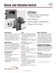
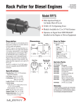
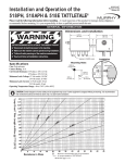
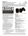
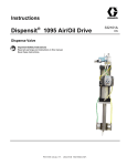
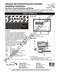
MDTM-8907N
Revised 10-07
Section 10
(00-02-0165)
Instructions for Installation and Operation
Model Series MDTM89,
Dual Temperature SWICHGAGE®
Please read the following information before installing. A visual inspection before mounting for any damage during shipping is
recommended. General information and installation instructions are intended for all MDTM89 Series models.
GENERAL INFORMATION
WARNING
BEFORE BEGINNING INSTALLATION OF THIS MURPHY PRODUCT
✔
✔
✔
✔
Disconnect all electrical power to the machine.
Make sure the machine cannot operate during installation.
Follow all safety warnings of the machine manufacturer.
Read and follow all installation instructions.
†
††
Description
Murphy's model MDTM89 is an electronic, dual-temperature monitor. It monitors two thermocouples, displays the temperature of the
thermocouple selected, and has adjustable trip points for each input.
A toggle switch provides for selection of the thermocouple to be displayed and/or the temperature trip point to be checked/adjusted. If
either trip point is reached, the associated output “turns on” and can
be used as a control signal, or to initiate alarms and/or shutdown.
Specifications
Power Requirements (Operating Voltages):
MDTM89-A: 100 to 350†† VDC, CD ignition, negative
ground (FET outputs).
MDTM89-B: 100 to 350†† VDC, CD ignition, negative or
positive ground (SCR outputs).
MDTM89-C: 12 to 24† VDC, negative ground, 15 milliwatts
(FET outputs).
MDTM89-D: 120 VAC (MDTM89-C with 120 V isolation module #IT-1)
(FET outputs.) Model NOT approved by CSA or Factory Mutual.
Power Consumption: CD ignition: 350 µa @ 100V;
120 VAC: 0.6 watts; 24 VDC: 0.5 watts.
Outputs: Model B: output turns on above trip point; output turns off
when power is switched off; two (2) isolated SCR outputs, 0.5 amp
@ 250 VDC.
Models A, C and D: output turns on above trip point; output turns off
below trip point; two (2) isolated FET outputs, 0.5 amp @ 250 VDC.
Ambient Cold Junction Compensation Range:
32 to 122°F (1°C from 0 to 50°C).
Operating Temperature: -4 to 158°F (-20 to 70°C).
Storage Temperature: -40 to 300°F (-40 to 150°C).
Case: Die cast aluminum.
Reset Differential: FET models: Decreases 3 Degrees (°F or °C).
SCR model: turn input power off to reset.
Measurement Range: Monitor Range 0-1999°F or °C (specify “F” or
“C” in part number).
Accuracy: With J-type thermocouple: from 150-1200°F (66°-649°C)
±1.5% of reading. With K-type thermocouple: from 400-2000°F
(204-1076°C) ±1.5% of reading. At calibration temperature.
Laboratory Approvals: CSA† and Factory Mutual†† approved for
Class I, Division 2, Group D, hazardous locations).
Thermocouple Lead Length: 150 ohm lead resistance affects monitor accuracy less than 1°.
Trip Point Accuracy: ±3°F (±2°C) of reading.
Trip Point Adjustment Range: 0-1999 Degrees.
MDTM89 Interface Capabilities
Model
Power Source
Rating
LCDT
S1400
MARK II and IV
TATTLETALE®
CD Ign., 120 VAC, 12/24 VDC
120 VAC or 12/24 VDC
CD Ignition, pos. or neg. grnd
CD Ign., 120 VAC, 12/24 VDC
Cl.I, Div.1, Gr.D, Haz. areas*
Cl.I, Div.1, Gr.D, Haz. areas*
Cl.I, Div.2, Gr.D, Haz. areas**
Non-Hazardous areas
*An isolation barrier is needed between the MDTM89 and an Annunciator rated for
Class I, Division 1, Group D, Hazardous Areas.
**When used with approved ignition. Contact Murphy for details.
†
When used with approved ignitions or 12-24 VDC. Contact Murphy for details.
Approved for CD ignition, 80–250 VDC.
††
MDTM-8907N page 1 of 4
MOUNTING DIMENSIONS
Mount the MDTM89 temperature SWICHGAGE® in a place where it
will be protected from rain and splashing water. A minimum distance of
12 in. (305 mm) from any ignition coils or coil leads should be maintained. The MDTM89 flush mount case is intended for mounting in a flat
panel .032 in. (1 mm) to .125 in. (3 mm) thick.
Front View
4-3/4 in.
(121 mm)
Back View
Side View
4-1/4 in.
(108 mm)
First, cut a 4-3/4 in. (121 mm) diameter hole and three 1/4 in. (6 mm)
diameter fastening holes as shown below. Insert the SWICHGAGE®
from the back side of the panel. Using the three 10-24 screws, included
with the SWICHGAGE®, secure to the panel.
Screw for
Equipment Ground
Mounting Hole Pattern
Remove Jumper(s)
to Install
Thermocouple
4-3/4 in.
(121 mm)
TC1
TC2
5-1/2 in.
(140 mm)
120
120
1/4 in.
(6 mm)
typical
diameter
2-39/64 in. radius
(66 mm)
4 in.
(102 mm)
WIRING AND ADJUSTMENT INFORMATION
CAUTION: Perform the wiring operation with the power source “OFF”. Make sure the voltage and current requirements are
within the SWICHGAGE® ratings. Keep all high voltage wiring, such as spark plug wires away from THERMOCOUPLES
AND EXTENSION WIRING. Before wiring determine the voltage and polarity for the application.
One Thermocouple Only
Even though the MDTM89 is a dual temperature monitor, it will monitor
and display one temperature with equal results.
When monitoring one temperature, always jumper the unused thermocouple terminals on the back of the MDTM89 with a short length of wire.
The unused channel will display approximate ambient temperature.
Table 1. Thermocouple Extension Wire Color Code
Thermocouple Thermocouple
Type
Extension Wire
Color Code/Material
Positive Lead
Negative Lead
J
Jx
White/Iron
Red/Constantan
K
Kx
Yellow/Chromel
Red/Alumel
Open Thermocouple Input
An open thermocouple input forces the monitor into upscale overrange.
The monitor indicates an overrange by displaying the numeral “1” in the
left most digit of the display. An overrange will turn on the trip point output, for the respective thermocouple.
MDTM89 Wiring and Adjustment
Instructions
Table 2. Thermocouple Extension Wire Loop
Resistance in Ohms per Foot at 68°F
Size
AWG No.
Type “J”
14
.07
.146
16
.137
.230
18
.222
.374
20
.357
.586
24
.878
1.490
A. Using Thermocouple Extension Wire
1. After thermocouple installation, connect the thermocouple leads to
the MDTM89 according to the instructions.
IMPORTANT: Use correct wire for the thermocouple selected.
USE ONLY THERMOCOUPLE EXTENSION WIRE.
2. If the thermocouple leads are not long enough you will need to use
shielded thermocouple extension wire. The thermocouple extension
wires, from your thermocouple lead wires to the terminals of the
MDTM89, must be of the same material as the thermocouple lead
wires. (See Table 1.)
Type “K”
Thermocouple lead length: 150 ohm lead resistance affects monitor accuracy less than 1°.
MDTM-8907N page 2 of 4
WIRING AND ADJUSTMENT INFORMATION
CAUTION: The use of non thermocouple wire will cause
inaccurate temperature sensing and erratic operation.
3. When connecting the thermocouple extension wire to your thermocouple leads, twist the wire connections, then install wire nuts,
such as ceramic type, which have no metal insert.
DO NOT SOLDER.
To prevent problems of interference from electrical noise, DO NOT
route thermocouple wires in the same conduit or within 12 inches
(304 mm) of ignition wires or alternating current conductors.
Metallic-overbraided, thermocouple wire is recommended. It provides electrical shielding as well as protection against wear and
abrasion.
B. Connecting Thermocouple Wires (ungrounded thermocouple)
1. Remove factory installed jumpers or shunts from TC1 and TC2
terminals before connecting thermocouple(s).
2. Connect the thermocouple leads to the thermocouples. Observe
lead polarity. See Table 1 for thermocouple extension lead color
code and thermocouple polarity.
NOTE: Before continuing to the next step, decide which thermocouple
is to be identified as TC1 and which is to be identified as TC2.
A wire marker should be installed on each end of the thermocouple lead to identify TC1 and TC2.
3. Connect the positive lead of thermocouple TC1 to the positive (+)
terminal of terminal strip TC1.
4. Connect the negative lead of thermocouple TC1 to the negative (-)
terminal of terminal strip TC1.
5. Connect the positive lead of thermocouple TC2 to the positive (+)
terminal of terminal strip TC2.
6. Connect the negative lead of thermocouple TC2 to the negative (-)
terminal of terminal strip TC2.
C. Connecting Output Wires
Wire the SWICHGAGE® trip point outputs as shown in the typical
wiring diagrams on the back of this page.
D. Connecting Power Wires
1. Determine the voltage and the polarity of the input power before
attempting to connect the power leads to the MDTM89.
2. On CD ignitions, connect the shutdown lead to the MDTM89
ignition input as shown in the diagrams below.
Operation Test
NOTE: Perform the Operation Test after the MDTM89 is installed and wired
appropriately.
1. a. Rotate the trip point potentiometers TC1 and TC2 clockwise until an
audible click is heard or detente is felt. These are 12-turn
potentiometers.
b. Start the engine or power up the monitor.
2. a. Set the display selector switch to the TC1 position to display the TC1
temperature.
b. Next depress and hold the “Push to Read” trip point push button to
display the TP1 setting.
c. Rotate the TC1 trip point potentiometer counterclockwise until the
display reading is equal to the temperature reading observed in
step 2. a.
d. Trip point TP1 will turn on and trip the shutdown device or alarm;
verify by observation.
e. Rotate the trip point potentiometer TC1 clockwise several turns to
turn off TP1.
f. Reset alarm or shutdown device.
3. a. Set the display selector switch to the TC2 position to display the TC2
temperature.
b. Next, depress and hold the “Push to Read” trip point push button to
display the TP2 setting.
c. Rotate the TC2 trip point potentiometer counterclockwise until the
display reading is equal to the temperature reading observed in
step 3.-a.
d. Trip point TP2 will turn on and trip the shutdown device or alarm;
verify by observation.
e. Rotate trip point potentiometer TC2 clockwise several turns to turn
off TP2.
f. Reset alarm or shutdown device.
TRIP POINT ADJUSTMENT INFORMATION
Trip Point Adjustments
Face Plate Diagram
1. Power up the temperature monitor by turning on power or by
starting engine.
2. Set the display selector switch to the TC1 position.
3. Depress the “Push to Read” trip point push button to read trip point.
4. Rotate the trip point potentiometer TC1 until the display indicates
the desired trip point temperature for TC1.
5. Set the display selector switch to TC2 position.
6. Depress the “Push to Read” trip point push button to read the
trip point.
7. Rotate the trip point potentiometer TC2 until the display indicates
the desired trip point temperature for TC2.
A. Trip point/display
toggle switch.
B. Readout digital
display.
C. Trip point
potentiometers.
D. Push to read trip
point button.
B
C
A
D
DETAIL
12 turn
potentiometers
MDTM-8907N page 3 of 4
TYPICAL WIRING DIAGRAMS
Thermocouple
TC1 Input
See Table 1 for
wire color code.
12/24
VDC
12/24
TC1
NC
TC2
NEG
12/24 VDC Power
TP1
TP2
Load
Thermocouple
TC2 Input
Load
See Table 1 for
wire color code.
Power
Source
Power
Source
Thermocouple
TC1 Input
See Table 1 for
wire color code.
120 VAC/24 VDC
Isolation
Module
H
120 VAC
N
12/24
ISOLATION
MODULE
24 VDC
TC1
NC
TC2
NEG
120 VAC Power
TP1
Option NOT approved by
CSA or Factory Mutual
TP2
Load
Thermocouple
TC2 Input
Load
See Table 1 for
wire color code.
Power
Source
CD
Ignition
Power
Source
Thermocouple
TC1 Input
Negative
Ground
See Table 1 for
wire color code.
100-150 VDC
150-350 VDC
100-150
150-350
TC1
TC2
NEG
CD Ignition—Negative Ground
TP1
TP2
Load
Thermocouple
TC2 Input
Load
See Table 1 for
wire color code.
Power
Source
Power
Source
TPI
Typical TTD Hook-up
Warranty
A limited warranty on materials and workmanship is given with this FW Murphy product.
A copy of the warranty may be viewed or printed by going to www.fwmurphy.com/support/warranty.htm
FW MURPHY
CONTROL SYSTEMS & SERVICES DIVISION
COMPUTRONIC CONTROLS, LTD
P.O. Box 470248
Tulsa, Oklahoma 74147 USA
+1.918.317.4100 Fax: +1.918.317.4266
E-mail: [email protected]
P.O. Box 1819
Rosenberg, Texas 77471 USA
Phone: 281.633.4500 Fax: 281.633.4588
E-mail: [email protected]
Web site: www.fwmurphy.com
41 - 43 Railway Terrance Nechells
Birmingham B7 5NG UK
Phone: +44.1213.278500 Fax: +44.1213.278501
E-mail: [email protected]
Web site: www.computroniccontrols.com
FRANK W. MURPHY, LTD
FW MURPHY INSTRUMENTS (HANGZHOU) CO. LTD
Church Rd Laverstock
Salisbury SP1 1QZ UK
Phone: +44.1722.41005 Fax: +44.1722.410088
E-mail: [email protected]
Web site: www.fwmurphy.co.uk
77 23rd Street
Hangzhou Economic & Technological Development Area
Hangzhou, Zhejiang, 310018, China
Phone: +86.571.8684.8886 Fax: +86.571.8684.8878
INDUSTRIAL PANEL DIVISION
Fax: 918.317.4124
E-mail: [email protected]
MURPHY POWER IGNITION
Web site: www.murphy-pi.com
fwmurphy.com
www.
Printed in U.S.A.
0889795
In order to consistently bring you the highest quality, full featured products, we reserve the right to change our specifications and designs at any time.
MDTM-8907N page 4 of 4