1
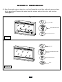
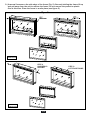
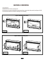
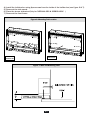
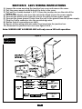
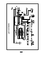
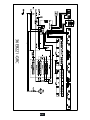
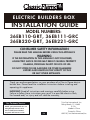
ELECTRIC BUILDERS BOX
Electric Builder Box
INSTALLATION GUIDE
MODEL NUMBERS:
36EB110-GRT, 36EB111-GRC
36EB220-GRT, 36EB221-GRC
CONSUMER SAFETY INFORMATION
PLEASE READ THIS MANUAL BEFORE USING THIS APPLIANCE
WARNING
IF THE INFORMATION IN THIS MANUAL IS NOT FOLLOWED,
AN ELECTRIC SHOCK OR FIRE MAY RESULT CAUSING PROPERTY
DAMAGE, PERSONAL INJURY OR LOSS OF LIFE.
DO NOT STORE OR USE GASOLINE OR OTHER FLAMMABLE
VAPORS AND LIQUIDS IN THE VICINITY OF THIS
OR ANY OTHER APPLIANCE.
Thank you and congratulations on your purchase of a Classic Flame electric
builder box. Please read the installation instructions before installing and
operating this appliance.
IMPORTANT: Read all instructions and warnings carefully before using.
Failure to follow these instructions may result in a possible electric shock,
fire hazard and/ or injury and will void the warranty.
For Customer Service:
E-Mail: [email protected]
In English Call: 866-661-1218
In French Call: 866-374-9203
In Spanish Call: 866-661-1218
E-1
Twin-Star International, Inc.
Delray Beach, FL 33445
U.S.A.
Made in China
Printed in China
©2010,Twin-StarInternational,Inc.
LISTINGS AND CODE APPROVALS
THE BUILDERS BOX SERIES HAS BEEN TESTED AND APPROVED IN ACCORDANCE WITH
CSA AND UL STANDARDS FOR FIXED AND LOCATION DEDICATED ELECTRIC ROOM HEATERS.
MODEL SPECIFICATIONS
VOLTAGE
MODEL NUMBER
DESCRIPTION
36EB110-GRT
36” TRADITIONAL
120
36EB220-GRT
36” TRADITIONAL
208/240
36EB111-GRC
36” CONTEMPORARY
120
36EB221-GRC
36” CONTEMPORARY
208/240
RATED POWER
WATTS
1440
2100/2800
1440
2100/2800
BTU
AMPS
4400
12
6700/8900 10.1/11.7
4400
12
6700/8900 10.1/11.7
WARNING
THE INSTALLATION OF THE BUILDER BOX MUST COMPLY WITH THE APPLICABLE
LOCAL AND / OR NATIONAL ELECTRICAL CODES AND UTILITY REQUIREMENTS.
THIS INSTALLATION SHOULD BE ENTRUSTED TO ONLY QUALIFIED
PERSONNNEL WHERE REQUIRED BY LAW.
INSTALLATION OVERVIEW
(Please read all instructions and user manual before installation)
Section 1.) Prepare product for installation.
Section 2.) Rough in framing following the recommended dimensions.
Section 3.) Recommended power supply wire specifications.
Section 4.) Mount the unit.
Section 5.) 120V wiring instructions.
Section 6.) 208/240V wiring instructions.
Section 7.) Function check.
Section 8.) Finish wall construction.
Section 9.) Electrical wiring diagram.
E-2
SECTION 1: PREPARATION
1.) Open the master carton, stone box , and wall mounted control box and make sure you have
all the parts listed. Remove the parts from the cartons and put them in a safe location
( see figure 1.)
Figure 1
3
Sign Wire
DOWN
UP
FLAME
TIMRER
Control Box with bracket
HEAT
SLEEP
FLAME
EMBERS
Remote Control
36EB110-GRT
36EB220-GRT
Sign Wire
DOWN
UP
FLAME
TIMRER
DOWN
UP
LIGHT EFFECTS
Control Box with bracket
HEAT
SLEEP
FLAME
DOWN
LIGHTS
UP
LIGHTS
AUTO
Remote Control
Stones
36EB111-GRC
36EB221-GRC
E-3
2.) Unscrew 2 screws on the side edge of the frame (Fig. 2). Securely holding the frame lift up
and pull away from the unit to remove the frame. Do not remove the protective plastic
film at this time. Place the frame in a safe place( see figure 2.)
Figure 2
3
36EB110-GRT
36EB220-GRT
STEP 1
UNSCREW 2
SCREWS
36EB111-GRC
36EB221-GRC
E-4
STEP 2
LIFT FRONT PANEL
SECTION
2: FRAMING
Section 1: Framing
This fireplace is a zero clearance design. No combustibles can be placed on the top surface
of the fireplace. Combustibles may be installed to the edge of the unit. Insulation and vapor
barrier should be placed a minimum of 2 inches from the unit. Build the framing according
to the specifications shown in the below table & figure 3.
MODEL
36EB110-GRT
36EB220-GRT
36EB111-GRC
36EB221-GRC
A
B
8”
35”
C
23.8”
D
24”
E
18”
F
G
H
36”
33.5”
34.7”
I
J
23.6”
7.8”
K
L
M
51”
36”
36”
Framing Specification: Figure 3
H
L
D
E
G
I
K
F
J
Section 3: Recommended Power Supply Wire
Specifications
For 36EB110-GRT & 36EB111-GRC installations use three non-metallic
sheathed cables with ground wire for the power supply. Use the appropriate wires to
meet local and national electrical codes for rated power consumption.
For 36EB220-GRT & 36EB221-GRC installations use four non-metallic
sheathed cables with ground wire for the incoming power supply. Use the appropriate
wires to meet local and national electrical codes for rated power consumption.
Recommended Wire and Fusing Requirements
Use appropriate wire to meet local and national electrical codes for rated power
consumption. All wire gauges should be 12 gauge solid wires with a dedicated 15 amp
breaker for 120 volts. For 208/240 volts Builders Box models use two dedicated
15 amp breakers.
Allow at least 8 in of service cable for connecting power supply wire to junction box on
fireplace insert when installing before finishing wall. Allow up to 4 feet of service cable
for connecting power supply wire to junction box on fireplace insert after finishing wall.
The control box is supplied with a six meter long cable.
E-5
M
SECTION 4: MOUNTING
Install Method:
1.) Remove front frame (see figure 2).
2.) Remove the screws holding side panels and then remove the side panels (see figure 4 & 5).
3.) Insert the builders box into the opening in the framing.
Figure 4: Mounting Tab Location
36EB111-GRC
36EB221-GRC
36EB110-GRT
36EB220-GRT
Figure 5: Wall and Mounting Tabs
36EB110-GRT
36EB220-GRT
36EB111-GRC
36EB221-GRC
E-6
4.) Install the builders box using 4pcs screws from the inside of the builder box (see figure 6 & 7).
5.) Remount the side panels.
6.) Place the stones as desired.(Only for 36EB111-GRC & 36EB221-GRC )
7.) Remount the front frame.
Figure 6: Mounting Tab Location
Place sto
nes here.
36EB110-GRT
36EB220-GRT
36EB111-GRC
36EB221-GRC
Figure 7: Wall and Mounting Tabs
E-7
SECTION 5: 120V WIRING INSTRUCTIONS
1.) Loosen the screw securing the junction box cover and remove the cover.
2.) Pull the power supply wires through the hole in the cover.
3.) Pull out the 4 wires marked L, N, G, S from the junction box on the side of the
builder box.
4.) Connect the black L wire from the unit to the black L from the power supply.
5.) Connect the white N wire from the unit to the white N from power supply.
6.) Connect the green ground G wire from the unit to the ground from the power supply.
7.) Plug the S wire connector into the provided sign wire.
8.) Ensure that all connections are tight.
9.) Secure all the wiring with wire-caps, then insert into the junction box.
10.) Remount the junction box cover (see figure 8 & 9.)
Note: 36EB110-GRT & 36EB111-GRC will only run on 120 volt operation.
Figure 8
120 V
Configration
CONTROL
E-8
SECTION 5: 208/240V WIRING INSTRUCTIONS
1.) Loosen the screw securing the junction box cover and remove the cover.
2.) Pull the power supply wires through the hole in the cover.
3.) Pull out the 5 wires marked L1, L2, N, G, S from the junction box on the side of the
builder box.
4.) Connect the black L1 wire and red L2 from the unit to the two dedicated 15 amp
lines from the power supply.
5.) Connect the white N wire from the unit to the white N from power supply.
6.) Connect the green ground G wire from the unit to the ground from the power supply.
7.) Plug the S wire connector into the provided sign wire.
8.) Ensure that all connections are tight.
9.) Secure all the wiring with wire-caps, then insert into the junction box.
10.) Remount the junction box cover (see figure 8 & 9.)
Note: 36EB220-GRT & 36EB221-GRC will only run on 208/240 volt operation.
Figure 9
208/240 V
Configration
CONTROL
E-9
SECTION 6: INSTALL CONTROL BOX
1. Mount the control box bracket to the wall using provided screws.
2. Connect control panel wire to extension cable.
3. Insert the control box to the bracket and finish the control box installation.
Figure 10
1
2
3
E-10
SECTION 6: CHECK & TEST
1.) Recheck that all the wiring works. Check that all connections are tight and correct to the
manual.
2.) Switch on the power supply to the unit.
3.) Press the POWER button on the control box.
4.) Using the wall controls test all the functions to ensure they are working correctly.
If any functions do not work recheck the wiring using sections 4 and 5 of this guide.
5.) Use the remote control to operate the unit, check all the functions.
6.)Finish wall construction work.
Caution: When the wiring is complete a thorough
“testing cycle” must be performed to check the
operation of the unit PRIOR to the wall / area being
closed up, tiled, and/or bricked.
E-11
SECTION 10: WIRING SCHEMATIC
36EB110-GRT
E-12
36EB220-GRT
E-13
36EB111-GRC
E-14
36EB221-GRC
E-15