1
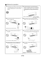
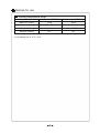
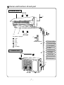
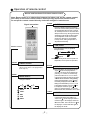
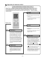
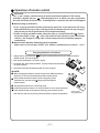
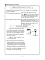
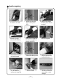
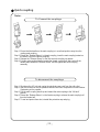
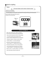
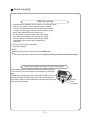
Installation and Operation Manual Room Air Conditioners R410A Split Type DC INVERTER QUICK COUPLING SERIES ECO906SQ ECO1206SQ t t t t Please read this installation manual completely before installing the product. When the power cord is damaged, replacement work shall be performed by authorized personnel only. Installation work must be performed in accordance with the national wiring standards by authorized personnel only. Contact the authorised service technician for repair or maintenance of this unit. Register your air conditioner Model information can be found on the CE label. Please register your product online at www.ecoair.org. For your future convenience, record the model information below. ____________________________________ MODEL NUMBER ____________________________________ SERIAL NUMBER ____________________________________ PURCHASE DATE Congratulations! You have purchased the very latest in room air conditioner technology. Your new EcoAir high efficiency room air conditioner will give you many years of dependable service. Many features have been built into your EcoAir air conditioner to assure quiet operation, the best circulation of cool, dry air, functional controls, and the most economical operation. CONTENTS Operation and maintenance ■Warning: Before operating your unit .............................................................. 1 ■BS Plug Wiring................................................................................................ 2 ■Operation and maintenance-notices .... for operation ........................................ 3 ■Notices for operation...................................................................................... 4 ■Notices for use ........................................................................................... 5 ■Names and functions of each part ................................................................ 7 ■Operation of remote control........................................................................... 8 ■Emergency operation.................................................................................... 13 ■Clean and care............................................................................................. 14 ■Troubleshooting............................................................................................. 16 Installation service ■Notices for installation................................................................................... 19 ■Installation dimention diagram...................................................................... 21 ■Ready your tools........................................................................................... 22 ■Install indoor unit.......................................................................................... 24 ■Install outdoor unit....................................................................................... ■Quick coupling............................................................................................... 27 ■Check after installation and test operation................................................... ■Circuit diagram.............................................................................................. ■Installation and Maintenance of Healthy Filter............................................. ■Service & Warranty...................................................................................... 32 28 33 34 35 You must not dispose this appliance as unsorted waste or with you domestic household waste. Please observe local regulation for disposal. Most Local authorities have specific collection systems for appliances where disposal are free of charge to the end user. WARNING: Before operating your unit WARNING Make sure the wiring is adequate for your unit. Before you install or relocate this unit, be sure that the amperage rating of the circuit breaker complies with the amp rating listed in Figure 1. Electrical Shock Hazard Always consult a qualified electrician regarding the power supply to the appliance. DO NOT use an extension cord. The cord provided will carry the proper amount of electrical power to the unit; an extension cord will not. Do not use plug adapters. Do not use an extension cord. Do not remove ground prong. Make sure that the Power Supply is compatible with the air conditioner. Always plug into a grounded 3 prong outlet. Failure to follow these instructions can result in death, fire, or electrical shock. Safety Precautions Input Rated Amp Model Power Supply Up to 12,000 Btu/h (3.5kW) Input Rated Amp (Switch/Fuse) 13A 18,000 Btu/h (5kW) 220-240V ~ 50Hz More than 18,000 Btu/h (5kW) Note : The supply voltage can not be less than the rate voltage of the air conditioner. 20A 32A Warning t t t t t t t t t t Installations must comply with the national wiring standards and conform to local authority regulations. Incorrect installation could cause injury due to fire, electric shock, the unit falling or leakage of water. Consult the dealer from whom you purchased the unit or a suitably qualified installer. Do not modify or attempt the air conditioner without permission or instruction from the manufacturer. Install the unit securely and ensure location of installation can bear the weight of the air conditioner. Do not install or operate the air conditioner in areas where harmful or flammable gas are present. Any maintenance on the air conditioner must only be carried out after disconnecting from the electric mains supply. Any repairs must be carried out by a suitably qualified engineer. Ensure the air conditioner is connected to an earthed power supply of the correct rating. Do not unplug the air conditioner whilst in operation. Always use the control panel to start and stop the air conditioner. Do not obstruct or cover the inlet and outlet grilles. Do not use the air conditioner in a wet room, such as bathroom. Do not allow spray or pour water over directly onto the air conditioner. Always handle the air conditioner with dry hands. For the best cooling performance and highest energy efficiency Keep the filter clean Make sure that your air conditioner is always in top performing condition by cleaning the filter regularly. Instructions for removing and cleaning the filter can be found on page 12. Provide good air flow Make sure the airflow to and from the unit is clear. Airflow is critical to good operation. It is important for both indoor and outdoor units. Unit placement If your air conditioner can be placed in a window or wall that is shaded by a tree or another building, the unit will operate even more efficiently. Using drapes or blinds on the sunny side of the dwelling will also add to your unit’s efficiency. Insulation Good insulation will be a big help in maintaining desirable comfort levels. Doors should have weather stripping. Be sure to caulk around doors and windows. Note: if you switch from Cool mode to Fan Only, and switch back to COOL mode, there is a three minute delay before the compressor comes back on. 1 BS Plug Wiring (For models up to 12000 Btu) Wiring Instructions: Should it be necessary to change the plug please note the wires in the mains lead are coloured in accordance with the following code : BLUE - NEUTRAL BROWN – LIVE GREEN AND YELLOW - EARTH As the colours of the wires in the mains lead of this appliance may not correspond with the coloured markings identifying the terminals in your plug, proceed as follows: 1. The BLUE wire is the NEUTRAL and must be connected to the terminal which is marked with the letter N or coloured BLACK. 2. The BROWN wire is the LIVE and must be connected to the terminal which is marked with the letter L or coloured RED. 3. The GREEN/YELLOW is the EARTH and must be connected to the terminal which is marked with the letter E or or coloured GREEN OR GREEN/YELLOW. 4. Always ensure that the cord grip is positioned and fastened correctly. If a 13A (BS 1363) fused plug is used it must be fitted with a 13A fuse. If in doubt consult a qualified electrician. Wiring for a 13 Amp Plug (BS1363) Please note. The Earth Terminal is marked with the letter E or 2 Earth Symbol. Operation and maintenance-notices for operation ȝ Earth: The ground ȝBe sure to pull out the power ȝ Select the most appropriate tembe connected! plug when not using the air conditioner for a long time. perature. Keep room cooer than outside about 5 degree. If not, please ask the qualified personnel to install. Furthermore, don't connect each wire to the gas pipe, water pipe, drainage pipe or any other improper places. ȝ Don't leave windows and doors open for a long time while operating the air conditioner. It can decrease the air conditioning capacity. ȝ Please note whether the installed stand is firm enough or not. If it is damaged, it may lead to the fall of the unit and cause the injury. Otherwise, the accumulated dust may cause fire or electric shock. ȝ Don't block the air intake or outlet vents of both the outdoor and indoor units. It can decrease the air conditioning capacity or cause a malfunction. ȝ Don't step on the top of the outdoor unit or place something on it. As falling off the outdoor unit can be dangerous. It can preclude the electricity wasted. ȝ Keep combustible spray away from the units more than 1m. It can cause afire or explosion. ȝ Don't attempt to repair the air conditioner by yourself. The wrong repair will lead to an electric shock or fire, so you should contact the service center to repair. Notices for operation ★If the supply cord is damaged, it must be replaced ★The airflow direction can be adjusted appropriately. At operating, adjust the vertical airflow direction by adjusting the louvers of upward/downward direction. And then, hold two ends of left and right louver to adjust the horizontal airflow. by the manufacturer or its service agent or a similarly qualified person in order to avoid a hazard. Louver of left/right direction ★ Don't insert your hands or stick into the air Louver of upward/ downward direction. ★ Don't blow the wind to animals and plants intake or outlet vents. directly. It can cause a bad influence to them. Otherwise it will cause accident. ★ Don't apply the cold wind to the body for a ★ Don't use the air conditioner for other purposes, long time. such as drying clothes, preserving foods, etc. It can cause the health problems. ★ Splashing water on the air conditioner can ★ Don't place a space heater near the air cause an electric shock and malfunction. conditioner. Or CO toxicosis may occur for incomplete burning. 4 Notices for use Working principle and special functions for cooling Principle: The air conditioner transfers heat from the indoor area to the outdoor area, thus reducing the indoor room temperature, using heat pump technology. Anti-freezing function: In COOL mode under low ambient temperature, frost will form on the heat exchanger. When the indoor heat exchanger temperature decreases to below 0℃, the indoor unit microcomputer will stop the compressor from running. This is normal and is important to protect the compressor and prolongs the life of the air conditioner. Working principle and special functions for heating Principle: * The air conditioner transfers heat from outdoor area to the indoor area, thus increasing * the indoor room temperature using heat pump heating technology. In extreme cold temperature, the condenser will require defrosting regularly. You may need to use alternative heating equipment. Defrosting: * When outdoor temperature is low but high humidity, frost will form on outdoor unit that will affect the heating, resulting in the auto defrost function where the heating will stop for 8-10mins. * During the auto defrosting, the fans of indoor and outdoor unit will stop. * During the defrosting, the indoor indicator flashes, the outdoor unit may emit * vapour. This is normal and is not a malfunction. Once defrosting is completed, the heating will recover automatically. Anti-cool wind function: In the “Heat” mode, the indoor fan operation will be delayed to prevent cold air being expelled for additional comfort. It is apparent during the start of the heating mode, upon completion of the Auto Defrosting and heating during very low temperature. It is normal for the indoor unit to expel low air flow and the louver to rotate to a certain position: 1. 2. In “Heat” mode, upon starting, the compressor running is delayed. In “Heat” mode, upon reaching the set temperature, the compressor stops running for about 1 min. 5 Notices for use Working temperature range o Indoor side DB/WB( C) Maximum cooling o Outdoor side DB/WB( C) 48/30 Minimum cooling 35/24 21/15 Maximum heating 24/--- 21/15.5 Minimum heating 20/--- -15/- 21/- The operating temperature range (outdoor temperature) for the cooling is 21 ℃~ 48℃ and for the heating unit is -15 ℃~ 48℃. 6 Names and functions of each part Indoor unit Air in Ń Ł Ň ņ ń Ņ Air out The pattern in displayer˖ ł ˖Cool Wireless remote control ˖Dry ˖Fan Ł Power cable ł Remote control ˖Heat ˖Run Ń Front panel ˖Se t temp. ń Filter Ņ Guide louver Outdoor unit ņ Wall pipe Air in Ň Bind tape ň Connection wire ʼn Drainage pipe ň ʼn Air out Operation of remote control Names and functions of wireless remote control Note: Ensure there is no obstruction between the indoor unit and the remote control; Don't drop or throw the remote control; Don't spill any liquid onto remote control. Do not put the remote control directly under the sunlight or heated areas. SLEEP Signal transmitter SLEEP button ƽ Press this button, Sleep On and Sleep Off can be selected. After powered on,Sleep Off is defaulted. After the unit is turned off, the Sleep function is canceled. After Sleep function set up, the signal of Sleep will display. In this mode, the time of timer can be adjusted. Under Fan and Auto modes, this function is not available. In sleep mode, setting temperature is adjusted automatically. FAN FAN button Remote control ƽ Press this button once, fan speed will change as below: Low fan Middle fan High fan Note:Under the Dry mode, the fan speed isn't adjustable, low fan speed is imperative, ON/OFF ON/OFF button CLOCK ƽ Press this button to power on and off . (This clears the timer or sleeping function previously set). MODE CLOCK button ƽ Press this button, the clock can be set up, signal blink and display.Within 5 seconds, the value can be adjusted by pressing + or - button, if continuously press this button for 2 seconds above, in every 0.5 seconds, the value on ten place of Minute will be increased 1. During blinking, repress the Clock button, signal will be constantly displayed and it denotes the setting succeeded. After powered on, 12:00 is defaulted to display and signal will be displayed. If there is signal be displayed that denotes the current time value is Clock value, otherwise is Timer value. MODE button ƽ Press this button, the running mode will change as follows. AUTO LIGHT COOL DRY LIGHT button ƽ Press this button to select LIGHT on or off FAN in the display. When the LIGHT on is set,the icon will be displayed and the HEAT indicator light in the displayer will be on. When the LIGHT off is set, the icon will be displayed and the indicator light on the display will be off. Operation of remote control Names and functions of wireless remote control Notice: This is a general use remote controller, it could be used for the air conditioners with multifunction; For some function, which the model dosen't have, if press the corresponding button on the remote controller that the unit will keep the original running status. + + button ƽ Press the + button to increase the setting temp by 1℃. Press the button continuously to accelerate the change in the temperature (range 16~30℃). Remote control - - button ƽ Press the - button to decrease the setting BLOW temp by 1℃. BLOW button Press the button continuously to accelerate the change in the temperature (range 16~30℃). ƽ Press this button, can turn on or turn off the drying.In Cool and Dehumidifying mode, press this button and will display "BLOW", at this time the Blow is turned on. If repress this button,"BLOW" will be concealed, at this time the Blow function is turned off. After powered on, Blow OFF is defaulted. When operating the ON/OFF button, or switching mode to Cool or Dehumidifying mode,the Blow function will keep the original status. If unit is turned off, Blow OFF only can be set up and send the signal. In Auto, Fan as well as Heat mode, Blow function can not be set up and there is no "BLOW" displaying. TURBO TEMP TEMP button ƽ After powered on, the setting temperature displaying is defaulted, (according to customers requirements to display, if there is no requirement that will default to display the presetting temperature and there is no icon displayed on wireless remote control). Press this button, (When displaying ) , will display presetting temperature; (when displaying TURBO button ) will display indoor ambient temperature, current displaying status will not be ƽ Set turbo on or off (the characters of turbo will appear or disappear ) by pressing this key under cooling or heating mode. Once energized, the unit will be return to non turbo mode. This function can not be set under auto, dehumidify or fan mode. Use the turbo mode to increase the fan speed. changed. If current displays indoor ambient temperature, if received the other remote control signal, it will display presetting temperature, 5s later, will back to display the ambient temperature. Operation of remote control Names and functions of wireless remote control Notice: This is a general use remote controller, it could be used for the air conditioners with multifunction; For some function, which the model dosen't have, if press the corresponding button on the remote controller that the unit will keep the original running status. TIMER ON TIMER ON BUTTON ƽ Remote control SWING UP AND DOWN BUTTON ƽ ƽ ƽ TIMER OFF Press this button, to set up swing angle, The unit is defaulted to the Simple Swing which circularly changes as below: Mode. TIMER OFF BUTTON ƽ Press this button to activate or deactivate the up and down swing function. ƽ When unit is turned off, synchronously to switch between the Simple Swing Mode and Stationary Swing Mode. blinks 2 seconds. In Stationary swing mode, press this button, the angle for Up and down swing as show in below: OFF ƽ Once press this key to enter into TIMER OFF setup, in which case the TIMER OFF icon will blink. The method of setting is the same as for TIMER ON. press "+" and Up and down swing buttons, ƽ Timer On setting: Signal “ON” will blink and display, signal will conceal, the numerical section will become the timer on setting status. During 5 seconds blink, by pressing ˇ or ˉ button to adjust the time value of numerical section, every press of that button, the value will be increased or decreased 1 minute. Hold pressing ˇ or ˉbutton, 2 seconds later, it quickly change, the way of change is: During the initial 2.5 seconds, ten numbers change in the one place of minute, then the one place is constant, ten numbers change in the tens place of minute at 2.5 seconds speed and carry. During 5s blink, press the Timer button, the timer setting succeeds. The Timer On has been set up, repress the timer On button, the Timer On will be canceled. Before setting the Timer, please adjust the Clock to the current actual time. When up and down swing louver mode is selected, the swing louver will immediately stop at current position when switched off. Operation of remote control Guide for operation- General operation 1. Press ON/OFF button to start the unit after powering the main unit on. (Note: The big -guide louver and small-guide louver will close automatically during Power on). 2. Press MODE button to select desired running mode. 3. Press +/ - button to set the desired temperature. (You cannot set the temperature in AUTO mode, it is preset) 4. Press FAN button to set fan speed, (AUTO FAN, LOW, MID or HIGH). 5. Pressing button, to set swing mode. Guide for operation- Optional operation 1. Press SLEEP button, set the sleep mode. 2. Press TIMER ON and TIMER OFF button, to set the scheduled timer on or timer off. 3. Press light button to control display light on or off. 4. Press turbo button to set this function on or off. . Introduction for special function ȝ About blow function This function indicates that moisture on evaporator of indoor unit will be blowed after the unit is stopped to avoid mould. 1. Having set blow function on: After turning off the unit by pressing ON/OFF button indoor fan will continue running for about 10 min. at low speed. In this period, press blow button to stop indoor fan directly. 2. Having set blow function off: After turning off the unit by pressing ON/OFF button, the complete unit will be off directly. ȝ About AUTO RUN When AUTO RUN mode is selected, the setting temperature will not be displayed on the LCD, the unit will be in accordance with the room temp. automatically to select the suitable running method and to make ambient comfortable. ȝ About turbo function If start this function, the unit will run at super-high fan speed to cool or heat quickly so that the ambient temp. approachs the preset temp. as soon as possible. Operation of remote control ȝ About lock Press + and - buttons simultaneously to lock or unlock the keyboard. If the remote controller is locked, the icon will be displayed on it, in which case, press any button, the mark will flicker for three times. If the keyboard is unlocked, the mark will disappear. ȝ About swing up and down 1. Press swing up and down button continuously more than 2s,the main unit will swing back and forth from up to down, and then loosen the button, the unit will stop swinging and present position of guide louver will be kept immediately. 2. Under swing up and down mode, when the status is switched from off to , if press this button again 2s later, status will switch off status directly; if press the button within 2s, the change of swing status will also depend on the circulation sequence stated above. ȝ About switch between Fahrenheit and Centigrade Under status of unit off, press MODE and - buttons simultaneously to switch ćanḑ Changing batteries and notices Slightly to press the place with , along the arrowhead direction to push the back cover of remote control. (As show in figure) Take out the old batteries. (As show in figure) Insert two new AAA 1.5V dry batteries, and pay attention to the polarity. (As show in figure) Attach the back cover of remote control. (As show in figure) ȝ NOTE: ƽ When changing the batteries, do not use the old or different batteries, otherwise, it can cause the malfunction of the remote control. ƽ If the remote control will not be used for a long time, please take them out, and don't let the leakage liquid damage the remote control. ƽ The operation should be in its receiving range. ƽ It should be placed at where is 1m away from the TV set or stereo sound sets. ƽ If the remote control cannot operate normally, please take them out, after 30s later and reinsert, if they cannot normally run, please change them. Sketch map for changing batteries Emergency operation Displayer indicator light control of indoor unit It's a special selective button for the users, who are not accustomed to light at sleeping. Ș Ș Get the displayer indicator light on: When setting the light function, the mark display on the remote controller screen by pressing this button. In which case,the dissplayer indicator light will be on if the AC receives this signal. Get the displayer indicator light off: If cancel the light function,the mark will disapper on the remote controller screen by pressing this button. In which case, the displayer indicator light will be off if the AC receives this signal. Emergency operation If the wireless remote control is lost or broken, please use the manual switch button. At this time, the unit will run at the Auto mode, but the temperature and fan speed cannot be changed. The operation was shown as below: Manual switch To open the panel, the manual switch is on the displayer box. Ș Turn on the unit: At unit turned off, press the button,the unit will run at Auto mode immediately.The microcomputer will accord to the indoor temperature to select (Cooling, Heating, Fan) and obtain the comfortable effect. Ș Turn off the unit: At unit turned on, press the button, the unit will stop working. Clean and care Caution ● ● ● Turn power off and pull out the power plug before cleaning air conditioner, or it may cause electric shock. Never sprinkle water on the indoor unit and the outdoor unit for cleaning because it can cause an electric shock. Volatile liquid (e.g. thinner or gasoline) will damage the air conditioner. (So wipe the units with a dry soft cloth, or a cloth slightly moistened with water or cleanser.) Clean the front panel When cleaning the front panel, please dip the cloth into the water temperature of 45đ below, then to dry the cloth and wipe the dirty part. Note: Please do not to immerse the front panel in water, due to there are microcomputer components and circuit diagrams on the front panel. Clean the air filter (Recommended once every three months) NOTE: If dust is much more around the air conditioner, the air filters should be cleaned many times. After taking off the filter, don't touch the fin of indoor unit, in order to avoid hurt your fingers. Ś Take down the air filter At the slot of surface panel to open an angle, pull the air filter downward and take it out, please see the Fig a, b. D E ś Clean the air filter To clean the dust adhering to the filters, you can either use a vacuum cleaner, or wash them with warm water the water with the neutral detergent should below 45 degree) ,and dry it in the shade. NOTE: Never use water above 45đ to clean, or it can cause deformation or discoloration. Never parch it by fire, or can cause a fire or deformation. Ŝ Insert the air filter Reinsert the filters along the direction of arrowhead, and then to cover the cover and clasp it. Clean and care Check before use ŚBe sure that nothing obstructs the air outlet and intake vents. śCheck that ground wire is properly connected or not. (Important) ŜCheck that the batteries of the remote control changed if remote is not working. ŝCheck that the installation stand of the outdoor unit is damaged or not. If damaged, please contact the dealer. Maintain after use ŚTurn main power off. śClean the filter, clean the indoor and outdoor units’ panels. ŜClear dust and obstructions from the outdoor unit. ŝRepaint the rubiginous place on the outdoor unit to prevent it from spreading. Ş Adopt a special shield to cover the outdoor unit, avoid the rain water and dust from entering the unit where possible. Troubleshooting CAUTION Don't attempt to repair the air conditioner by yourself, it can cause an electric shock or fire. Please check the following items before asking for repair, it can save your time and money. Phenomenon Troubleshooting Not operate immediately when the air conditioner is restarted. Once the air conditioner is stopped, it will not operate in approximately 3 minutes to protect itself. ƽ Waiting There's unusual smell blowing from the outlet after operation is started. ƽ The unit has no peculiar smell by itself. If it does smell, it is due to the smell accumulated in the ambient air in the room. ƽ Solution method: Cleaning the filter. If problem persists, obtain a maintenance service from your installer. Sound of water flow can be heard during the operation. ƽ In COOL mode, sometimes the mist is emitted from the air outlet vent. ƽ Creaking noise duting starting or stopping the unit. ƽ ƽ The air conditioner is started, when it is running the compressor started or stopped running, or the unit is stopped, sometimes there is swoosh or gurgle, the sound is due to refrigerant flowing and is not a malfunction. When the indoor temperature and humidity are very high, this is normal. This is caused when the room air is cooled down. After running for a while the indoor temperature and humidity will be under control and the mist will . stop. This is caused by slight expansion of the panels due to the changes of temperature. This is normal and is not a malfunction. Troubleshooting Phenomenon Troubleshooting ƽ Has the power been shut down? The unit is not running ƽ Is power connected properly? ƽ Is the circuit protection device tripped off or not? ƽ Is voltage higher or lower? (Tested by professionals) Breaking off ƽ Is the TIMER correctly used? Cooling (Heating) efficiency is not good. ƽ Is Temp. setting suitable? ƽ Were inlet and outlet vents obstructed? ƽ Is filter dirty? ƽ Are the windows and doors closed? ƽ Did Fan speed set at low speed? ƽ Is there any heat sources in the room? Remote control is not available . ƽ The unit is interfered by abnormal or frequent functions switchover occasionally the controller cannot operate. At this time, you need to pull out of the plug, and reinsert it. ƽ Is it in its receiving range? Or obstructed? To check the voltage in remote control inside is charged, otherwise to replace the batteries. ƽ Whether the wireless remote control is damaged. If water leakage in the room. ƽ The air humidity is on the high side. ƽ Condensing water over flowed. ƽ The connection position of indoor unit drainage pipe is loosed. If water leakage in outdoor unit. ƽ When the unit is running in COOL mode, the pipe and connection of pipe would be condensed due to the water cooled down. ƽ When the unit is running in Auto Defrosting mode the ice thawed and flowed out. ƽ When the unit is running in HEAT mode, the water adhered on heat exchanger dripped off. Noise from indoor unit emitted. ƽ The sound of fan or compressor relay is switching on or off. ƽ When the defrosting is started or stop running, it will sound. That is due to the refrigerant flowed to the reverse direction. Troubleshooting Phenomenon No air delivery from indoor unit. Troubleshooting ƽ In HEAT mode, when the indoor temperature is very low, air delivery will be delayed for up to 5 minutes. ƽ In HEAT mode, when the outdoor temperature is low or high humidity, frost may from on the outdoor heat exchanger. This will require defrosing before air delivery. The defrosing can take up to 20 minutes. ƽ During the defrosting, water and vapor is produced so condensation will occur. ƽ In dehumidifying mode, indoor fan will stop, in order to avaoid condensed water to be vaporized again. The air delivery is delayed during this action. Moisture on air outlet vent. ƽ If unit is running under the high humidity for a long time, the moisture will be condensed on the air outlet grill and drip off. Immediately stop all operations and plug out, contact the dealer in following situations. There is harsh sound during operation. The terrible odors emitted during operation. Water is leaking in the room. Air switch or protection switch often breaks. Water Spillage into unit. There is an abnormal heat in power supply cord and power plug. Stop running and pull out of the plug. Notices for installation Important Notices When removing the unit to the other place, please firstly contact with the authorized Maintenance Center in the local area. Basic Requirements For Installation Position Install in the following place may cause malfunction. If it is unavoidable contact with service center please: ƽ Place where strong heat sources, vapors, flammable gas or volatile object are emitted. ƽ Place where high-frequency waves are generated by radio equipment, welders and medical equipment. ƽ Place where a lot of salinities such as coast exists. ƽ Place where the oil (machine oil) is contained in the air. ƽ Place where a sulfured gas such as the hot spring zones is generated. ƽ Other place with special circumstance. Indoor Unit Installation Position Selection The air inlet and outlet vent should be far from the obstruction, make sure that the air can be blown through the whole room. Select a position where the condensing water can be easily drained out, and the place is easily connected for outdoor unit. Select a location where the children can not reach. Can select the place where is strong enough to withstand the full weight and vibration of the unit. And will not increase the noise. Be sure to leave enough space to allow access for routine maintenance. The height of the installed location should be 250cm or more from the floor. Select a place about 1m or more away from TVset or any other electric appliances. Select a place where the filter can be easily taken out. Make sure that the indoor unit installation should correspond with installation dimension diagram requirements. Do not use the unit in the immediate surroundings of a laundry a bath a shower or a swimming pool. Outdoor Unit Installation Position Selection Select a location from which noise and outflow air emitted by unit will not inconvenience neighbors, animals, plants. Select a location where there should be sufficient ventilation. Select a location where there should be no obstructions cover the inlet and outlet vent. The location should be able to withstand the full weight and vibration of the outdoor unit and permit safe installation. Select a dry place, but do not expose under the direct sunlight or strong wind. Make sure that the outdoor unit installation dimension should accord with installation dimension diagram, convenient for maintenance, repair. Select a place where it is out of reach for the children. Select a place where will not block the passage. Notices for installation Safety Requirements For Electric Appliances 1. The power supply should be used the rated voltage and AC exclusive circuit, the power cable diameter should be satisfied. 2. Don't drag the power cable emphatically. 3. It should be reliably earthed, and it should be connected to the special earth device, the installation work should be operated by the professional. The air switch must have the functions of magnetic tripping and heat tripping, in order to protect the short circuit and overloading. 4. The min. distance from the unit and combustive surface is 1.5m. 5. The appliance shall be installed in accordance with national wiring regulations. 6. An all-pole disconnection switch having a contact separation of at least 3mm in all poles should be connected in fixed wiring. Note: ● Make sure that the Live wire or Zero line as well as the earth wire in the family power socket can not be wrong connected, there should be reliable and no short circuit in the diagram. ● wrong connection may cause fire. Earthing requirements 1. Air conditioner is type I electric appliance, thus please do conduct reliable earthing measure. 2. The yellow-green two-color wire in air conditioner is earthing wire and cannot be used for other propose. It cannot be cut off and be fix it by screw, otherwise it would cause electric shock. 3. The earth resistance should accord to the National Criterion. 4. The user power must offer the reliable earthing terminal. Please don't connect the earthing wire with the following place: ķ Tap water pipe. ĸ Gas pipe. Ĺ Contamination pipe. ĺ Other places that professional personnel consider them unreliable. 5. The model and rating values for fuses according the silk print on fuse cover or related PCB board. Installation dimension diagram Installation dimension diagram Space to the ceiling Above Space to the wall Above Above Space to the wall Above Air outlet side Above Space to the floor The dimensions of the space necessary for correct installation of the appliance including the minimum permissible distances to adjacent structures Space to the obstruction Above Ș Air inlet side Ab e ov Above Space to the wall Space to the wall Above ve bo A Air outlet side Ready your tools Ready for the following tools: Electric SDS drill. (If you use an ordinary drill you will need an SDS adaptor) Hammer Screwdrivers. Posidrive or crosshead Tape measure Prepare hole cutter Spirit level Number 14 (7mm) masonary drill Pencil and chalk 1.5 inch number 10 screws. roundhead slotted Small stepladder 7mm wallplugs Protective glasses and mask Pipe and cable detector 4 inch plastic ties (pack) Ready your tools Ready for the following tools: 2 inch Pipe clips Circuit breaker when drilling inside and out Garden gloves when lifting the outdoor unit Dustsheets Foam Filler Silicone sealer and gun Install indoor unit 1. Check the area for any hidden wires or pipes. 2. Mark the righthand backplate screw position. 3. Remove the backplate and drill a 7mm hole. 4. Tap home a 7mm wallplug. 5. Screw the backplate to the wall using 1.5 inch number 10 screws. 6. Check level, mark the other holes and swing the backplate away. 7. Drill the rest of the holes and tap in wallplugs 8. Fix the backplate to the wall. 9. Mark the hole centre make sure the 3.5 inch cutter will clear the backplate. 10. Drill the hole at a slight downward angle. When you feel the pilot drill exit the outside wall stop 11. Finish the hole from the outside to keep it clean 12. Feed the cord and drain hose carefully through the wall Install indoor unit 13. Undo the power lead and break out the plastic lead tab. 14. Hook the indoor unit onto the top of the backplate. 15. Lock the bottom of the unit onto the base of the backplace. Notes: Install the rear panel 1. Always mount the rear panel horizontally. Due to the water tray of indoor unit has been adopted the both-way drainage design, the outlet of water tray should be adjusted slightly down when installing, that is taking the outlet of the water tray as the center of a circle, the included angle between the evaporator and level should be 0 or more, that is good for condensing water drainage. 2.Fix the rear panel on the wall with screws. (Where is pre-covered with plastic granula) 3.Be sure that the rear panel has been fixed firmly enough to withstand the weight of an adult of 60kg, further more, the weight should be evenly shared by each screw. Wall Space to the wall PP above Mark on the middle of it Gradienter Wall Space to the wall PP above Right Left º PP (Rear piping hole) Install the piping hole 0DNHWKHSLSLQJKROHɎLQWKHZDOODWDVOLJKWdownward slant to the outdoor side. 2.Insert the piping-hole sleeve into the hole to prevent the connecting piping and wiring from being damaged when passing through the hole. Indoor Outdoor Wall pipe Seal pad Ø Install indoor unit NOTE: Install the indoor unit ƽThe piping can lead out from left Gas side pipe When routing the piping and wiring from the left External connection electric wire Liquid side piping Tailing 2 Tailing 1 Gas side piping of the indoor unit, cut off the tailings Liquid side insulation Piping insulation Finally wrap it from the chassis if necessary (Show in Fig.1) Fig.1 Water drainage pipe with tape ŁCut off the tailings 1 when routing the wiring only; łCut off the tailings 1 and tailings 2 when routing Left rear both the wiring and piping. Take out the piping from body case, wrap the piping Left electric wire, water pipe with tape and pull them Right through the piping hole (As show in Fig.2) Fig.2 Mounting Right rear Hange the mounting slots of the indoor unit on the baord Fixing hook upper tabs of the rear panel and check if it is firm Mounting enough.(As show in Fig.3) plate The height of the installed location should be .2.5 m or more from the floor. Fig.3 Install outdoor unit 1. Gently bend the pipe at right angles to the wall. 2. Mark a vericle chalk line on the wall using a spirit level. 4. Mark the four unit fixing holes on the floor. 5. Remove the unit. Drill the 7mm holes and tap in the wallplugs. 3. Mark a chalk line on the floor to line up the outside unit with the connecting cord Notes: Install the water drainage pipe 1.For well draining, the drain hose should be placed at a downward slant 2.Do not wrench or bend the drain hose or flood its end by water. 3.When the long drainage hose passing through indoor, should wrap the insulation materials. Wrenched Bent Flooded Quick coupling 1. Push the drain hose onto the indoor unit outlet. 2. Remove the raincover from the side (Indoor Unit). 3. Slide the lug towards left side (1) from female coupling. 4. Push the male coupling connector (2) right inside female coupling. 5. Close the retaining clip (4), make sure the fingers of the clip are engaged on the back of the lug. 6. Push the electrical snap connector together. 7. Connect the 3 wires to the terminal board. 8. Clip on the raincover and fasten the retaining screw. 9. Fold the excess cord back on itseld and clip it with plastic ties. 10. Screw down the unit. You will need four washers (not supplied). 11. Fix the cord and drain hose to the wall. 12. Switch on at the mains, run test and check for any coolant or water leakage. Quick coupling Notes: To Connect the couplings Step 1: Ensure that the handle on the male coupling is in a reclined position away from the mating male coupling. Step 2: Retract the “Release Sleeve” on female coupling, insert the male coupling located on the indoor unit into the female coupling. Step 3: Release the "Release Sleeve" to the lock the male coupling into places. Step 4: Fold the male coupling handle towards the female coupling half and push until the handle seals behind the "Release Sleeve" and flat against the entire coupling assembly. To disconnect the couplings Step 1: Shut down the A/C unit and unplug the electrical power cord from the wall outlet. Step 2: Wait five minutes for the line pressure between the indoor compressor unit and outdoor Condensing unit to equalize. Step 3: Pull the male coupling handle up and toward the male coupling to the “full back” position. Step 4: Retract the “Release Sleeve” on the female coupling to release the male coupling half from the female half. Step 5: To seal and protect from dust, reinstall the protective cap and plug. Quick coupling Notes: Connect indoor and outdoor electric wires 1.Open the surface panel. 2.Remove the wiring cover. 3.Route the power connection cord and signal control wire (for cooling and heating unit only) from the back of the indoor unit and pull it toward the front through the wiring hole for connection. 4.Reassemble the clampand wiring cover. 5.Recover the surface panel. 1 %8 %. %1 <(*1 Electric heating belt When outdoor ambient sensor malfunction happened, both of the electric heating belts stop working, otherwise, it will run at the following control:.When Toutdoor ambient =-5. and the compressor doesn't started, that the compressor electric heating belt starts to work; Otherwise if compressor started or compressor doesn't start but Toutdoor ambient>-2. , the electric heating belt Electric heating belt will not work. Compressor doesn't start and -5.< T outdoor ambient =-2., compressor electric heating belt keeps the original state.. W hen Toutdoor ambient= 3., the condenser electric heating belt work; Otherwise, if Toutdoor ambient>6 ., the condenser electric heating belt will not work. 3.<Toutdoor ambient=6., the condenser electric heating belt will keep the original state. Quick coupling Electric wiring Disassemble the handle on the outdoor unit right side plate. Take off wire clamp. Connect and fix power connect cord (for cooling and heating unit,connect and fix power connect cord and signal control wire)to terminal of line bank. Wiring should fit that of indoor unit. Fix the power connection cable with wire clamp, (for cooling and heating unit, use the wire clamp to fix the power connection cable and the signal control wire), then connect the corresponding connector. Ensure wire has been fixed well. Install the handle. NOTE: Ș Wrong wiring may cause spare parts malfunction. Ș After the cable fixed, make sure there should be a free space between the connections. Condensate drainage of outdoor unit (Only for heating) The condensate and defrosting water formd during heating in the outdoor unit can be properly discharged by drainage pipe . Installation method:set the drain connection in Ø 25 hole of the chassis has been installed and then connect drainage pipe with drain nozzle,so that condensate and defrosting waer can be properly discharged Chassis Drain connection Check after installation and test operation Check after installation Items to be checked Possible malfunction Has it been fixed firmly? The unit may drop, shake or emit noise. Have you done the refrigerant leakage test? It may cause insufficient cooling(heating) capacity Is heat insulation sufficient? It may cause condensation and dripping. Is water drainage well? It may cause condensation and dripping. Is the voltage in accordance with the rated voltage marked on the nameplate? Is the electric wiring and piping connection installed correctly and securely? Has the unit been connected to a secure earth connection? It may cause electric malfunction or damage the part. It may cause electric malfunction or damage the part. It may cause electrical leakage. Is the power cord specified? It may cause electric malfunction or damage the part. Is the inlet and outlet been covered? It may cause insufficient cooling(heating) capacity. Has the length of connection pipes and refrigerant capacity been recorded? The refrigerant capacity is not accurate. Test Operation Before test operation Do not switch on power before installation isfinished completely. Electric wiring must be connected correctly and securely. All the impurities such as scraps and thrums must be cleared from the unit. Test operation method Switch on power, press "ON/OFF" button on the wireless remote control to start the operation. Press MODE button, to select the COOL, HEAT, FAN to check whether the operation is normal or not. Circuit diagram Indoor Unit Outdoor Unit 33 Installation and Maintenance of Healthy Filter Installation Instructions 1. Forcibly pull the panel for a specific angle from the two ends of the front panel according to the arrow direction. Then pull the air filter downwards to remove it. (See Fig.a) Fig. a 2. Mount the healthy filter onto the air filter,(as shown in Fig.b). If the air filter cannot be installed, please mount the healthy filter on the front case. (as shown in Fig.c) Fig. b Air filter Healthy filter Healthy filter Fig. c 3. Mount the air filter properly along the arrow direction in Fig.d, and then close the panel cover. Fig. d Cleaning and Maintenance Take out the healthy filter before cleaning and reinstall it after cleaning according to the installation instruction. Pay special attention to that silver ion filter can't be cleaned with water, while active carbon, photocatalyst, low temperature conversion (LTC) catalyst, formaldehyde eliminator, catechin or mite killing filter can, but can't with brush or hard things. Dry it in the shade or sun after cleaning, but not by wiping. Service Life The healthy filter commonly has its usage lifetime for one year under normal condition. As for silver ion filter, it is invalid when its surface becomes black (green). Ș This supplementary instruction is provided for reference to the unit with healthy filter. If the graphics provided herein is different from the physical goods, the latter one shall prevail. The quantity of healthy filters shall be based on the actual delivery. ONE (1) YEAR LIMITED WARRANTY SAVE THIS WARRANTY INFORMATION EcoAir guarantees this product free from defects in materials and workmanship for a period of one (1) year from the date of purchase, limited to parts only. Faults arising from a faulty installation is specifically excluded. This unit must be operated under conditions as recommended, at voltages indicated on the unit. Any attempts made to service or modify the unit by unqualified technician, will render this WARRANTY VOID. The actual product may differ slightly from the illustration. This warranty is in addition to, and does not affect, your statutory rights. For after sales needs, please visit www.ecoair.org/service [email protected] or contact +44 845 474 3574 or email We recommend that you note the details of your purchase below and retain your original proof of purchase receipt with this manual. Keep these documents safe in the event of a warranty claim. Date of purchase: _____________________________ Purchased from (Dealer Name): _____________________________ Retailer name: _____________________________ Model number: _____________________________ Serial number: _____________________________ Date of installation: _____________________________ Copyright Reserved