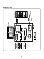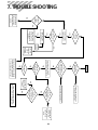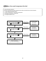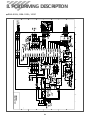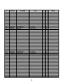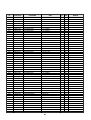
1
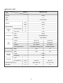
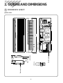
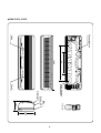
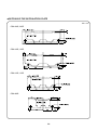
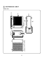
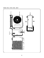
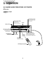
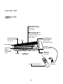
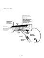
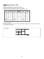
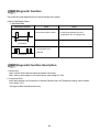
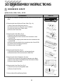
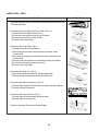
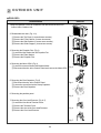
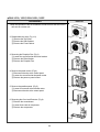
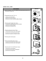
Manual de servicio
Split Acondicionador de Aire
Modelo:
DSA-095L
DSA-125L,125P
DSA-185L,185P
DSA-245L,245P
Aviso:
En este manual,algunas partes pueden cambiar sin previo aviso en la lista
de partes si usted necesita la ultima informacion por favor dirigirse a
PPL(Parts Price List)Centro de informacion de
servicio(http.//svc.dwe.co.kr).
http;//svc.dwe.co.kr
Dic 2005
Contents
CONTENTS
1. Specifications..........................................................................................................2
2. Outline and Dimensions .........................................................................................6
3. Operation ..............................................................................................................14
4. Wiring Diagram.....................................................................................................25
5. Control Block Diagram .........................................................................................28
6. Electric Circuit Diagram........................................................................................31
7. Trouble Shooting ..................................................................................................33
8. PCB Driving Description.......................................................................................39
9. Key Components of Electronic Circuit.................................................................63
10. Disassembly Instructions .....................................................................................66
1) Indoor Unit ........................................................................................................66
2) Outdoor Unit .....................................................................................................70
3) Exploded Diagram (Indoor Unit)......................................................................73
4) Exploded Diagram (Outdoor Unit)...................................................................81
5) Control Box Assembly......................................................................................89
1. SPECIFICATIONS
◆DSA-095L
MODEL
DSA-095L
ITEM
Function
Cooling
Class
T1
Power
AC 230V/ 60Hz
Capacity
KJ/h
9,000
Btu/h
8,531
l/h
1.1
Running Current
A
3.6
Power Input
W
800
Dehumidification
Electrical
Data
Type
Rotary
Model
QK125KB✳ (LGE)
Compressor
Capacitor
Fan
Motor
25µF / 400VAC
Indoor Unit
Outdoor Unit
Type
Cross flow fan
Propeller fan
Capacitor
1.0µF 400VAC
2.0µF 400VAC
YDK-8-4A(Xiang Ming)
YDK-35-6A(Xiang Ming)
Motor Model Number
Sound Level (Hi)
dB(A)
39
48
Fan Speed (Hi)
RPM
1,350
880
Refrigerant
(R22)
Connection
Control
Charge Q'ty
g
680
Type
OD (Liquid/Suction)
Dimensions (W x H x D)
Net Weight
Capillary
Flare
in(mm)
1/4 (6.35)
3/8 (9.52)
mm
750 x 245 x 179
654 x 549 x 256
kg
7.0
34
2
◆DSA-125L, 125P
MODEL
DSA-125L, 125P
ITEM
Function
Cooling
Class
T1
Power
AC 230V/ 60Hz
Capacity
KJ/h
12,500
Btu/h
11,848
l/h
1.35
Running Current
A
4.7
Power Input
W
1,010
Dehumidification
Electrical
Data
Compressor
Type
Rotary
Model
QK156KA✳ (LGE)
Capacitor
35µF/ 370VAC
Division
Fan
Motor
Indoor Unit
Outdoor Unit
Type
Cross flow fan
Propeller fan
Capacitor
1.2µF 400VAC
3µF 400VAC
RP-13B(Welling)
YDK-50-6A(Xiang Ming)
Motor Model Number
Sound Level (Hi)
dB(A)
42
52
Fan Speed (Hi)
RPM
1,300
870
Refrigerant
(R22)
Connection
Control
Charge Q'ty
g
1,000
Type
OD (Liquid/Suction)
Dimensions (W x H x D)
Net Weight
Capillary
Flare
in(mm)
1/4 (6.35)
mm
815 x 285 x 195
kg
9.2
3
3/8 (9.52)
800 x 615 x 320
50
◆DSA-185L, 185P
MODEL
DSA-185L, 185P
ITEM
Function
Cooling
Class
T1
Power
AC 230V/ 60Hz
KJ/h
17,500
Btu/h
16,588
l/h
2.0
Running Current
A
7.2
Power Input
W
1,620
Capacity
Dehumidification
Electrical
Data
Compressor
Type
Rotary
Model
QJ250KA✳ (LGE)
Capacitor
35µF/ 370VAC
Division
Fan
Motor
Indoor Unit
Outdoor Unit
Type
Cross flow fan
Propeller fan
Capacitor
1.2µF 400VAC
3µF 400VAC
YDK-20-4A(Xiang Ming)
YDK-50-6A(Xiang Ming)
Motor Model Number
Sound Level (Hi)
dB(A)
48.1
56
Fan Speed (Hi)
RPM
1,370
870
Refrigerant
(R-22)
Control
Charge Q'ty
Capillary
g
1,070
Type
Flare
Connection
OD (Liquid/Suction)
Dimensions (W x H x D)
Net Weight
in(mm)
1/4 (6.35)
1/2 (12.7)
mm
1035 x 322 x 205
800 x 615 x 320
kg
11.7
50
4
◆DSA-245L, 245P
MODEL
DSA-245L, 245P
ITEM
Function
Cooling
Class
T1
Power
AC 230V/ 60Hz
KJ/h
23,500
Btu/h
22,275
l/h
2.7
Running Current
A
10.0
Power Input
W
2,220
Capacity
Dehumidification
Electrical
Data
Compressor
Type
Rotary
Model
QP325KBB (LGE)
Capacitor
40µF/ 400VAC
Division
Fan
Motor
Indoor Unit
Outdoor Unit
Type
Cross flow fan
Propeller fan
Capacitor
1.2µF 400VAC
3µF 400VAC
IC-9430DWKF7A(Sung shin)
A2929GS010(DMI)
Motor Model Number
Sound Level (Hi)
dB(A)
48.5
57
Fan Speed (Hi)
RPM
1,300
950
Refrigerant
(R-22)
Control
Charge Q'ty
Capillary
g
1,850
Type
Flare
Connection
OD (Liquid/Suction)
Dimensions (W x H x D)
Net Weight
in(mm)
3/8 (9.52)
5/8 (15.9)
mm
1080 x 298 x 200
872 x 675 x 325
kg
14.7
64
5
2. OUTLINE AND DIMENSIONS
1 INDOOR UNIT
◆DSA-095L
750
Connecting Pipe
Plate Mounting
MODE
FAN SPEED
ENTER/
CANCEL
TIMER
ON/OFF
SLEEP
REMOTE CONTROLLER
FAN DIR.
TURBO/MILD
REMOCON
REMOCON
Grille Insert
245
Frame Grille
Body
179
Plate Mounting
6
◆DSA-125L, 125P
815
MODE
FAN SPEED
ENTER/
CANCEL
TIMER
ON/OFF
SLEEP
FAN DIR.
TURBO/MILD
REMOCON
Insert Grille
Frame Grille
Body
7
Connecting Pipe
Plate Mounting
195
285
◆ DSA-185L, 185P
Filter-L
Connecting
Pipe
¿‹ Æ˘˜ ˙`
453
453
1035
1035
Filter-R
Plate
”fi `⁄˘˙
Mounting
MODE
FAN SPEED
ENTER/
CANCEL
TIMER
ON/OFF
SLEEP
FAN DIR.
TURBO/MILD
REMOCON
`⁄„«…–‚fi‚ ˜
Grille Insert
‰˙‡»–
‚Ø– ‚–
322
‰˙‡»– ‚ ˆ…
Body
205
8
◆DSA-245L, 245P
Connecting Pipe
Filter-L
430
710
1080
Grille Insert
MODE
FAN SPEED
ENTER/
CANCEL
TIMER
ON/OFF
SLEEP
FAN DIR.
TURBO/MILD
REMOCON
REMOCON
Body
200
Frame Grille
Plate Mounting
Filter-R
298
9
◆INSTALLING THE INSTALLATION PLATE
Unit : mm
• DSA-245L, 245P
• DSA-185L, 185P
• DSA-125L, 125P
• DSA-095L
10
2 OUTDOOR UNIT
◆DSA-095L
Inlet
Outlet
Foot Cushion
Cabinet Front
SVC Cover
549
Cabinet Side Panel Top Guide Support
11
324
Servise Valve
539
Inlet
Outlet
460
654
256
286
◆DSA-125L, 125P, 185L, 185P
Inlet
Outlet
Foot Cushion
Cabinet Front
Cabinet Side
Panel Top
Guide Support
12
400
SVC Cover
Servise Valve
589
615
Inlet
Outlet
580
800
320
360
◆DSA-245L, 245P
Inlet
Outlet
Foot Cushion
Cabinet Front
SVC Cover
Servise Valve
673
697
Cabinet Side
Panel Top
Guide Support
13
Inlet
Outlet
549
872
325
350
380
3. OPERATION
1 NAME AND FUNCTION OF PARTS
◆DSA-095L
Indoor Unit
Deodorizing Filter
Removes bad smells
from the air.
Electrostatic Filter
Removes dust
particles from the air.
Air In
Indoor Cover
Air Cleaning Filters
Removes dust and
prohibits germs.
Connection Cover
Fan Direction
(Up/Down)
Cold Air
Remote
Sensor
Remove cover to access
the AC connection from
this unit to the outdoor unit.
Indicators
Indicate the setting
.P
T
ME
FA
FA
MOD
EE
N SP
O
/N
SL
EE
F
NA
P
R/ ELE
TE DE
EN CANC
OM
/OFF
ON ELS
PE
T
L
14
R.
ID
.R
P TIMER
ED
LCD Remote Controller
N DI
D
O
FF
E
N
EC
O/M
RB
TU AF
N
S
ILD
MI
RE
T
NO
O
FF
E
ES
R
AC
TN
RE
E
ON
OC
M
RE
Power Plug
◆DSA-125L, 125P
Indoor Unit
Electrostatic Filter
Removes dust particles
from the air
(DSA-125L)
Electric Dust Collector
(Air clean Plasma)
Removes small dust and
generates (-) ions.
(DSA-125P)
Deodorizing Filter
Removes bad smells
from the air.
Air In
Indoor Cover
Air Cleaning Filters
Removes dust and
prohibits germs.
Fan Direction
(Up/Down)
Remote
Sensor
Cold Air
Indicators
Indicate the setting
TE
MP
.
MOD
E
O
FA N/O
N SP FF
SL FA
EE N
EE
P D
D
IR
FA
TIM .
FA
N
N DI
SP ER VAPS
ON
R.
EE
TIM /OFF
D
MO
ER
DE
EN
ON
TE
CA R/
SLE
NC
OFF
EP
EL
TU
RE RB
EN
SE O/M
TE
T
ILD
R
CA
NC
EL
RE
MO
CO
N
Connection Cover
Remove cover to access
the AC connection from
this unit to the outdoor unit.
Emergency/Remote
Switch
Slide to select the
desired position.
LCD Remote Controller
Power Plug
15
◆ DSA-185L, 185P
Indoor Unit
Electrostatic Filter
Removes dust particles
from the air
(DSA-185L)
Electric Dust Collector
(Air clean Plasma)
Removes small dust and
generates (-) ions.
(DSA-185P)
Deodorizing Filter
Removes bad smells
from the air.
Test/Emergency/
Remote Switch
Slide to select
the desired position.
Air In
Indoor Cover
Air Cleaning
Filters
Removes dust
and prohibits
germs.
Remote Sensor
Cold Air
Indicators
Indicate the
AC setting.
Fan Direction
(Up/Down)
TE
FA
MO
MP
N SP
.
EE
FA
D
DE
N DI
R.
/OFF
PS
ON
VA
SLEE
DEO/
RB
MO
TU
P TIMER
FA
ON
/OFF
R.TER/ EL
EN CANC
N DI
FA
N SP
TIM
EE
ER
SL
MILD
EE
D
P
RE
OF
F
EN
TE
SE
T
R CA
NC
EL
ON
LCD Remote Controller
Power Plug
N
CO
MO
E
R
16
◆ DSA-245L, 245P
Electrostatic Filter
Removes dust particles
from the air
(DSA-245L)
Deodorizing Filter
Removes bad
smells from the air.
Electric Dust Collector
(Air clean Plasma)
Removes small dust and
generates (-) ions.
(DSA-245P)
AIR IN
Indoor Cover
Air Cleaning Filters
Removes dust and
prohibits germs.
AIR OUT
Remote
Sensor
Fan Direction
(Up/Down)
Emergency/
Remote Switch
Indicators
Indicate the
AC setting.
FA
FA
MO
DE
N SP
EE
D
N DI
R.
R.
N DI
FA
D
EE
N SP
FA
ER
E
PS
P
VA R/ EL
MOD SLEE TIM
TE
ER
P /OMFF
EE TI
SL ON
EN CA
TU
RB
NC
O/MI
LD
ILD
O/M
RB
TU
R/ EL
TE NC
EN CA
/OFF
ON
LCD Remote
Controller
N
CO
O
M
RE
17
Power Plug
2 REMOTE CONTROLLER
Name of Each Button
Display
Displays information
pertaining to unit.
(
DSA-125P, 185P, 245P)
AUTO
ON/OFF Button
Press to turn the unit
on or off.
FAN SPEED Button
Press to select the fan speed
(High " ", Middle " ",
Low " ").
MODE Button
Press to cycle through the modes
(Auto/Quick/Cool/Fan/Dehumidifier)
SLEEP Button
Press to set the unit for
the sleep mode.
TEMPERATURE Buttons
Press to raise or lower
the desired temperature.
MODE
FAN SPEED
SLEEP
FAN DIR.
PLASMA Buttons
Press to clean the polluted air.
(DSA-125P, 185P, 245P)
PLASMA
TIMER
ON/OFF
ENTER/
CANCEL
FAN DIR. Button
Press to select up/down
direction for fan.
TURBO/MILD
TURBO/MILD
Press to be colder the unit.
TIMER ON/OFF Button
Press to set the unit of or on time.
(0.5, 1, 1.5, 2, 2.5, 3, 4, 5, 6, 8,
10, 12, 16, 20, 24hr)
TIMER ENTER/CANCEL Button
Press to enter a timer setting or
to cancel timer setting
COVER
Slide down to access most
of the remote buttons.
Slide down further to
access the battery
compartment.
18
3 DESCRIPTION OF FUNCTIONS
OFF-Timer
If you set time in OFF-Timer Mode, the unit will stop at the set time.
ON
Unit ON
Unit OFF
OFF
SET Time
HOUR
ON-Timer
If you set time in ON-Timer Mode, the unit will run at the set time.
Unit ON
ON
OFF
Unit OFF
SET Time
HOUR
Control of Room Temperature
(1) Range of setting temperature: 18~32°C
(2) Setting temperature: Operating temperature of compressor
COMP (ON)
COMP (OFF)
-1°C
0°C
+1°C
(RT-DT)
(COOLING)
*RT: ROOM TEMPERATURE
DT: DESIRED TEMPERATURE
(3) During the time of test operating, Fan (Indoor, Outdoor) and Compressor is running regardless of room
temperature.
Buzzer
If the Indoor Unit Display receive the signal of Remote Controller, you can hear the signal "beep –" or "beep,
beep".
(1) In the case of receiving ON/OFF signal-"beep" "beep"
(2) And so on-"beep"
19
Fan Speed (Indoor Unit)
(1) Motor speed (high speed, normal speed, low speed).
(2) Remote controller setting fan speed. (Auto, L, M, H, Natural)
(3) Relation of operating mode between fan speed. (legned: X-no relation)
FAN ONLY
COOL
DEHUMIDIFICATION
AUTO
QUICK
H
H
H
L
H
H
M
M
M
L
M
H
L
L
L
L
L
H
Auto
L
Auto
H
Natural
L
Natural
H
Auto
Natural
Natural
(4) Automatic Operation
If the unit is set in 'AUTO' mode, the unit operates automatically according to the room temperature to keep the
room temperature comfortable.
(COOLING)
20
Sleep Mode
(1) When you are going to sleep, select sleep switch and the unit controls the room to the desired temperature.
(The unit will not operate after 4 hour)
(2) For changing the temperature.
DT
+0.5°C
+0.5°C
+0.5°C
0
0.5
1.0
HOUR
(COOLING CYCLE)
(3) To cancel sleep mode, press the SLEEP button again or press the MODE button once.: the SLEEP
indicator will disappear in the display.
Emergency Operation
(1) When the remote controller is lost, damaged or the battery is discharged, the Emergency operation can be
used to run the unit.
(2) The setting conditions of Emergency operation are as follows.
• Operation mode: Quick
• Preset temperature:18°C
• Fan speed: High
* You cannot operate with remote controller.
21
Frost Prevention of Indoor Unit
When the unit operates at low ambient temperature, frost may appear on the Evaporator. When the indoor coil
temperature is lower than 0°C at the end of 10 minutes of continuous compressor operation from the start, the
microcomputer of the unit stops the compressor to protect the unit from the frost. The control procedure for
indoor coil freeze protection.
1) The compressor and outdoor fan turn off.
2) Indoor fan operates according to user set speed.
3) The normal operation returns when the indoor coil
temperature is higher than 7°C or equal to 7°C.
Compressor and
Outdoor Fan
ON
ON
OFF
Set speed
Indoor Fan
-1°C
+7°C
(Indoor coil temperature)
3 min. Time Delay of Compressor
In normal operation, there is a time delay of three minutes between turn off and turning back on including initial
power up.
Auto Mode
(1) In Auto Mode
After the indoor fan is operated for 20 seconds in the Auto Mode the unit will operate automatically by selecting
operating Mode according to the room temperature
(RT: Room temperature)
ROOM TEMPERATURE
OPERATING MODE
FLAP POSITION
> RT
DT-2°C ≤ RT ≤ DT+3°C
DT+3°C < RT
Cooling
Cooling Position
Dehumidifier
Cooling Position
Cooling
Cooling Position
DT-2°C
(2) Selecting Operating Mode Again
Room temperature meets desired temperature and the compressor stops running over 30 minutes, then the unit
selects operating Mode again.
22
Dehumidification Mode
1 Desired temperature < Room temperature
Outdoor Fan, Compressor : ON
Indoor Fan : Low speed
2 Desired temperature ≥ Room temperature
Compressor : 3 min/ON, 5 min/OFF
Fan Speed : low speed
3 Room temperature ≤ 18°C
Compressor : OFF
Fan speed : Low speed
Air Discharge Direction(only remocon operation)
The air discharge direction procedure is below.
Fixed
Up/Down
Fixed
Up/Down
COOLING POSITION
Quick Mode(Powerful Cooling)
1) Cooling Mode
1 Fan Speed: Super high speed
2 Air discharge direction: Fixed
3 Set temperature: 18°C (Fixed)
4 Compressor and Outdoor Fan
The air discharge direction procedure is below
Fixed
Up/Down
Up/Down
Fixed
23
Self-Diagnostic Function
The control will contain diagnostic test to verify the integrity of the system.
(1)Error Code Display Pattern
1 ON LAMP: Blink
LED BLINK PATTERN
CASE
NOTE
Room Sensor open or Short
• Continuously working to fix room
temperature 18°C in cooling mode.
• I/D coil sensor open or short
Do not working
• Compressor or electrical parts
of compressor error.
Continuously working
0.5s
8s
1 times blink
• Gas leak
2 times blink
Self Diagnostic Function Description
1. Sensor Error
Open or Short circuit of Sensors (Room and Indoor Coil Sensor)
Open : Micom, Input Voltage 0~0.3V, Short: Micom, Input Voltage 4.7~5.0V
2. Compressor Error
At the start operation, the Compressor is ON and 5 Minutes later, the Temperature change value of Indoor
Coil is below +/-2°C.
• Emergency Mode Operation detect only
24
4. WIRING DIAGRAM
Indoor Unit
◆ DSA-095L
◆ DSA-125L
◆ DSA-185L, 245L
25
Indoor Unit
◆ DSA-125P
◆ DSA-185P
◆ DSA-245P
26
Outdoor Unit
◆ DSA-095L
◆ DSA-125L, 125P
◆ DSA-185L, 185P
◆ DSA-245L, 245P
27
5. CONTROL BLOCK DIAGRAM
◆DSA-095L, DSA-125L, 125P
28
◆DSA-185L, 185P
29
◆DSA-245L, 245P
30
6. ELECTRIC CIRCUIT DIAGRAM
1 ELECTRIC CIRCUIT DIAGRAM
◆DSA-095L, 125L, 125P, 185L, 185P, 245L, 245P
1
Indoor Unit
Fan Motor
2
3
N
I.D.C
L
Y
TERMINAL
BLOCK
L
SWING
MOTOR
S
R
TRANSFORMER
TRIAC
RL1
COMP.
RELAY
Display Part
OVERLOAD
PROTECTOR
Control Part
Signal Receiver
OUTDOOR UNIT
FAN MOTOR
COMPRESSOR
ROOM AIR
SENSOR
CMC
Remote Controller
INDOOR COIL
SENSOR
31
FMC
Description
1. After the power ON/OFF button is pressed once, the relay and triac are turned ON or OFF per the remote
control setpoint.
– TRIAC is controlled per the fan speed selection.
– RELAY is controlled per the operation mode selection.
2. If the power ON/OFF button is pressed once more, the relay and triac are turn off and the unit stops
operation.
3. The unit turns on or off according to the temperature set point by sensing the room air temperature through
thermistor.
4. If the fan speed selection is set to the auto position, the fan speed is automatically controlled according to the
temperature difference between room temperature and temperature set point.
5. If you press the ON/OFF button during operating the unit, Relay and LED is OFF and the unit is OFF.
32
7. TROUBLE SHOOTING
Is the unit
display
mormal?
YES
NO
NO
check the failure
code according to
the self-diagonostic
(note 2)
Is the
unit display
normal?
YES
Outdoor unit does
not run?(note. 1)
YES
Does
the compressor run
normally?
YES
Indoor unit does
not run(note 1)
YES
Check the failure
code according to
the self diagnostic
(note 2)
NO
NO
Normal
check the
connecting
point of
magnetic
contactor
NO
Trouble
Is the power
applied to the
unit
YES
Is the
power normal?
check the voltage between
L & N of terminal
block
YES
press the power ON/OFF
button on remote controller
YES
Does the
beeper beep two
times?
YES
Is the display
all off?
YES
• Check the connector on display
PCB connected to control PCB
• Check the display PCB itself
NO
NO
NO
NO
Check power supply mains
or interconnection wires
Check the wiring of indoor
Is the
switch position
on switch pannel at
"Remote"
YES
YES
Does
control PCB
status LED repeat one
second "on and
off"?
• control PCB fault
• Micom or reset
IC fault
NO
• Check the remote signal receiver
• Check the connection between signal
receiver and control PCB
Place the switch
position to the
"Remote" and then
Check it once
more
33
Note 1)
1 Neither indoor unit nor outdoor unit runs.
Check the following points first. (There are following case in normal operation)
a. Is the timer mode set the "timer ON".
b. Is the timer mode set the "timer-OFF" and the time had passed?
2 Neither outdoor fan nor compressor runs while indoor fan runs.
Check following points first. (There are following cases in normal operation)
a. Is the temperature set point suitable?
b. Has the 3 minutes time guard for compressor operated?
Self-Diagnostic Function
• Error Code •
1 When the compressor do not run.
i) Check the voltage between L and Y of terminal block.
(Indoor Unit, Outdoor Unit)
ii) Check connecting wire of indoor unit and outdoor unit.
iii) Check relay RL1 on power P.C.B
2 Check fixing of indoor coil thermistor.
3 Check the GAS LEAKAGE of the pipe.
34
Neither Indoor Unit nor Outdoor Unit Runs
Confirm following statement.
When the unit operate normally, Sometimes the outdoor unit and indoor unit cannot operate.
1 Check the function select switch. Is it timer mode?
2 The function select switch locate the sleep mode and is the setting time over?
3 Is the setting mode DEHUMIDIFIER mode?
4 When the unit is DEHUMIDIFIER mode while in the auto mode, the outdoor unit and indoor unit does
not run.
The power is applied to the unit
Rating voltage
Check the voltge between L and
Y of terminal block
under 90%
Check the
Breaker or Fuse
Rating voltage more than 90%
No
Check the indoor unit display
is the display all off?
Yes
Press the ON/OFF switch of
Remote Control
No
Self Diagnostic
function is ON
Yes
No
Check according to
self Diagnostic function
Is the indoor unit display all off?
Control P.C.B defect
Pull out the power plug
and then insert the power plug
after 5 second
Control P.C.B is normal
Recheck from the beginning
35
Outdoor Unit Runs but Indoor Fan Do Not Run
Check rotation of indoor fan
NO
Check the Fan Motor
bearing and fan
Rating voltage
Check the power P.C.B.
Rotate indoor fan by hand
YES
Check input Voltage of Fan
Motor connector at power P.C.B
under 90%
The circuit for triac control
Rating Voltage more than 90%
Open or short
Check the winding resistance of
Indoor unit fan motor
Change of fan motor
Normal
Check the fan motor capacitor
Check the connecting wire of
indoor fan motor
Run again
No
Check the starting of indoor fan motor
Run again
36
Normal
Outdoor Fan and Compressor Do Not
Confirm following statement.
When the unit operate normally, Sometimes the outdoor unit and indoor unit cannot operate.
1 Is the setting temperature proper?
2 Is the unit during 3min. Time delay of compressor.
3 During frost prevention of lndoor unit.
4 During dehumidifier mode.
Rating voltage
Check the voltge between L and
Y of indoor unit terminal
under 90%
Rating voltage
Check the voltge between L and
Y of outdoor unit terminal
under 90%
Check the voltge between L and
Y of outdoor unit terminal
Rating voltage
under 90%
Check compressor,
outdoor fan motor individually
37
Check the wiring
and voltage
within doors
Check the
connecting wire
Check the
connecting wire
Only Compressor Do not Run
- Check the following at cooling mode
Rating voltage
Check the voltge between L and
Y of indoor unit terminal
less than 90%
Check the control P.C.B
the circuit for relay
driving.
Rating voltage more than 90%
Rating voltage
Check the voltge between L and
Y of outdoor unit terminal
less than 90%
Check the connecting
wire between indoor
and outdoor.
Rating voltage more than 90%
Check the wiring of outdoor unit
Check the compressor
(Check the winding resistance)
OK
Check the compressor capacitor
38
NG
Change the control
P.C.B
Open or Short
Change the
compressor.
8. PCB DRIVING DESCRIPTION
◆DSA-095L, DSA-125L, 125P
39
◆DSA-185L, 185P
40
◆DSA-245L, 245P
41
◆DSA-095L PART LIST (Control PCB Assy)
✔ Caution : In this Manual, some parts can be changed for improving, their performance without notice in the parts list. So, if you need the
latest parts information, please refer to PPL(Parts Price List) in Service Information Center (http://svc.dwe.co.kr).
No.
PART CODE
PART NAME
SPEC.
Q'TY UNIT
BD1
DS1NB80---
DIODE BRIDGE
S1NB80,800V
1
EA
BZ1
3105698200
BUZZER
DP-2520BA
1
EA
CA1
CN5XD104M-
C-ARRAY
6P(F5)X 104Z
1
EA
CA2
CN4XD104M-
C-ARRAY
5P(F4)X 104Z
1
EA
CA3
CN3XD104M-
C-ARRAY
4P(F3)X 104Z
1
EA
CAP1
CMXZ2G105K
CAPACITOR MYLAR
1UF,400VAC
1
EA
CC1
CCXE1H104M
C-CERA
104M 50VDC
1
EA
CC10
CCXE1H103M
C-CERA
103M 50VDC
1
EA
CC12
CCXE1H103M
C-CERA
103M 50VDC
1
EA
CC2
CCXE1H104M
C-CERA
104M 50VDC
1
EA
CC3
CCXE1H103M
C-CERA
103M 50VDC
1
EA
CC4
CCXE1H103M
C-CERA
103M 50VDC
1
EA
CC5
CCXE1H104M
C-CERA
104M 50VDC
1
EA
CC6
CCXE1H104M
C-CERA
104M 50VDC
1
EA
CC7
CCXE1H104M
C-CERA
104M 50VDC
1
EA
CC8
CDXE1H104M
C-MULTI
CR501B-Z5U,104Z,50V
1
EA
CC9
CCXE1H103M
C-CERA
103M 50VDC
1
EA
CE1
CEXE1V477C
C-ELEC
470MF 35V SD
1
EA
CE2
CEXE1C107C
C-ELEC
100MF 16V SD
1
EA
CE3
CEXE2W106C
C-ELEC
10UF 450V SD
1
EA
CE4
CEXE2W106C
C-ELEC
10UF 450V SD
1
EA
CE5
CEXE1C106A
C-ELEC
10UF 16V SS
1
EA
CE6
CEXE1C475A
C-ELEC
4.7UF 50V SS
1
EA
CL1
CLV-B3104M
C-LINE ACROSS
275V 104K(PILKOR)
1
EA
CL2
CLV-B3104M
C-LINE ACROSS
275V 104K(PILKOR)
1
EA
CLIP
3107000600
FUSE CLIP
AFC-520
2
EA
CN1
3108802500
WAFER
YW396-03AV
1
EA
CN2
3108802900
WAFER
YW396-05AV
1
EA
CN5
3108804800
WAFER
SMAW250-08
1
EA
CN6
3118700800
WAFER
SMAW250-06
1
EA
CN7
3118702310
WAFER
YMAW025-04R
1
EA
CY1
CH1BFB222K
C CERA
2200PF,250V,Y1
1
EA
D1
DZST02D200
DIODE
ST02D-200
1
EA
D2
DZUF203---
DIODE
UF203
1
EA
D3
DZN4007A--
DIODE
IN4007A
1
EA
FUSE
5FVLB3152L
FUSE GLASS TUBE
250V/50T 3.15A
1
EA
IC1
13GS5DH9--
MICOM (MAIN)
TMP87C846N-5DH9(Z)
1
EA
IC2
1TNY264P--
IC SMPS
TNY264P
1
EA
IC3
1L7805CV--
IC REGULATOR
L7805CV
1
EA
IC4
13GT62004A
IC DRIVER
ULN2004AP(M)
1
EA
EA
IC5
1KA7042P--
IC RESET
KIA7042P 5L
1
IC6
13GT62004A
IC DRIVER
ULN2004AP(M)
1
EA
JS7
3109400100
JUMPER
10MM
1
EA
L1
52C102K000
CHOKE COIL
1MH,0.5A
1
EA
L2
52F6010100
FILTER EMI
0.6*10*3TURN
1
EA
COIL
130UF 3A
1
EA
RESONATOR
CRTL8.00MSOT
1
EA
L3
52C1374001
OSC
5PCRTL8MS0
PC1
1TLP421---
IC PHOTOCOUPLER
TLP421
1
EA
PC2
1TLP421---
IC PHOTOCOUPLER
TLP421
1
EA
42
REMARK
No.
PART CODE
PART NAME
SPEC.
Q'TY UNIT
PCB
3104398104
PCB CONTROL
162.5X140X1.6T
1
EA
PT1
1TLP560J--
IC PHOTO COUPLER
TLP 560J
1
EA
R1
RD-4K101J-
R CARBON FILM
1/4 100 OHM J
1
EA
R11
RD-4K103J-
R CARBON FILM
1/4 10K OHM J
1
EA
R12
RD-4K102J-
R CARBON FILM
1/4 1K OHM J
1
EA
R13
RD-4K102J-
R CARBON FILM
1/4 1K OHM J
1
EA
R14
RD-4K102J-
R CARBON FILM
1/4 1K OHM J
1
EA
R15
RD-4K102J-
R CARBON FILM
1/4 1K OHM J
1
EA
R16
RD-4K102J-
R CARBON FILM
1/4 1K OHM J
1
EA
R17
RD-4K102J-
R CARBON FILM
1/4 1K OHM J
1
EA
R18
RD-4K102J-
R CARBON FILM
1/4 1K OHM J
1
EA
R19
RD-4K102J-
R CARBON FILM
1/4 1K OHM J
1
EA
R2
RD-2K102J-
RESISTOR
1/2W - 1K OHM J
1
EA
R20
RD-4K102J-
R CARBON FILM
1/4 1K OHM J
1
EA
R21
RD-4K102J-
R CARBON FILM
1/4 1K OHM J
1
EA
R22
RD-4K562J-
R CARBON FILM
1/4 5.6K OHM J
1
EA
R23
RD-4K102J-
R CARBON FILM
1/4 1K OHM J
1
EA
R25
RD-4K331J-
R CARBON FILM
1/4 330 OHM J
1
EA
R26
RD-4K331J-
R CARBON FILM
1/4 330 OHM J
1
EA
R28
RN-4K1272F
R METAL FILM
1/4 12.7K OHM F
1
EA
R29
RN-4K1272F
R METAL FILM
1/4 12.7K OHM F
1
EA
R3
RS01F470J-
R M-OXIDE FILM
1W 47 OHM J
1
EA
R30
RD-4K102J-
R CARBON FILM
1/4 1K OHM J
1
EA
R31
RD-4K102J-
R CARBON FILM
1/4 1K OHM J
1
EA
R32
RD-4K102J-
R CARBON FILM
1/4 1K OHM J
1
EA
R33
RD-4K102J-
R CARBON FILM
1/4 1K OHM J
1
EA
R34
RD-4K102J-
R CARBON FILM
1/4 1K OHM J
1
EA
R35
RD-4K102J-
R CARBON FILM
1/4 1K OHM J
1
EA
R36
RD-4K102J-
R CARBON FILM
1/4 1K OHM J
1
EA
R37
RD-4K102J-
R CARBON FILM
1/4 1K OHM J
1
EA
R39
RN-4K5621F
R METAL FILM
1/4 5.62K OHM F
1
EA
R4
RD-4K101J-
R CARBON FILM
1/4 100 OHM J
1
EA
R41
RN-4K7681F
R METAL FILM
1/4 7.68K OHM F
1
EA
R43
RD-4K102J-
R CARBON FILM
1/4 1K OHM J
1
EA
R5
RD-4K102J-
R CARBON FILM
1/4 1K OHM J
1
EA
R6
RD-4K513J-
R CARBON FILM
1/4 51K OHM J
1
EA
R7
RD-4K202J-
R CARBON FILM
1/4 2K OHM J
1
EA
R8
RD-4K683J-
R CARBON FILM
1/4 68K OHM J
1
EA
R9
RD-4K683J-
R CARBON FILM
1/4 68K OHM J
1
EA
RA1
RA8K5103J-
RESISTOR ARRAY
6P(5)X 103J
1
EA
RA2
RA8K4103J-
RESISTOR ARRAY
5P(4)X 103J
1
EA
RA3
RA8K3103J-
RESISTOR ARRAY
4P(3)X 103J
1
EA
RL1
5SC0101210
RELAY
UKH-12S
1
EA
T1
TSM3JZ47--
TRIAC
SM3JZ47
1
EA
TR1
TKRC102M--
TR
KRC 102-M (TAPPING)
1
EA
TRS1
5EMU1916--
TRANS SMPS
264P,1916
1
EA
VAR
D15G561K--
VARISTOR
15G561K/350V
1
EA
ZD1
DZN5241B--
DIODE ZENOR
1N5241B
1
EA
43
REMARK
◆DSA-125L, 125P PART LIST (Control PCB Assy)
✔ Caution : In this Manual, some parts can be changed for improving, their performance without notice in the parts list. So, if you need the
latest parts information, please refer to PPL(Parts Price List) in Service Information Center (http://svc.dwe.co.kr).
No.
PART CODE
BD1
BZ1
CA1
CA2
CA3
CAP1
CC1
CC10
CC12
CC2
CC3
CC4
CC5
CC6
CC7
CC8
CC9
CE1
CE2
CE3
CE4
CE5
CE6
CL1
CL2
CLIP
CN1
CN2
CN5
CN6
CN7
CN9
CY1
CY2
D1
D2
D3
FUSE
IC1
IC2
IC3
IC4
IC5
IC6
L1
L2
L3
L4
OSC
PC1
DS1NB80--3105698200
CN5XD104MCN4XD104MCN3XD104MCMXZ2G155K
CCXE1H104M
CCXE1H103M
CCXE1H103M
CCXE1H104M
CCXE1H103M
CCXE1H103M
CCXE1H104M
CCXE1H104M
CCXE1H104M
CDXE1H104M
CCXE1H103M
CEXE1V477C
CEXE1C107C
CEXE2W106C
CEXE2W106C
CEXE1C106A
CEXE1C475A
CLV-B3104M
CLV-B3104M
3107000600
3108802500
3108802900
3108804800
3118700800
3118702310
3108802800
CH1BFB472K
CH1BFB472K
DZST02D200
DZUF203--DZN4007A-5FVLB3152L
13GS5DH9-1TNY264P-1L7805CV-13GT62004A
1KA7042P-13GT62004A
52C102K000
52C102K000
52C1374001
52C102K000
5PCRTL8MS0
1TLP421---
PART NAME
DIODE BRIDGE
BUZZER
C-ARRAY
C-ARRAY
C-ARRAY
CAPACITOR MYLAR
C-CERA
C-CERA
C-CERA
C-CERA
C-CERA
C-CERA
C-CERA
C-CERA
C-CERA
C-MULTI
C-CERA
C-ELEC
C-ELEC
C-ELEC
C-ELEC
C-ELEC
C-ELEC
C-LINE ACROSS
C-LINE ACROSS
FUSE CLIP
WAFER
WAFER
WAFER
WAFER
WAFER
WAFER
C CERA
C CERA
DIODE
DIODE
DIODE
FUSE GLASS TUBE
MICOM (MAIN)
IC SMPS
IC REGULATOR
IC DRIVER
IC RESET
IC DRIVER
CHOKE COIL
CHOKE COIL
COIL
CHOKE COIL
RESONATOR
IC PHOTOCOUPLER
SPEC.
S1NB80,800V
DP-2520BA
6P(F5)X 104Z
5P(F4)X 104Z
4P(F3)X 104Z
1.5UF,400VAC
104M 50VDC
103M 50VDC
103M 50VDC
104M 50VDC
103M 50VDC
103M 50VDC
104M 50VDC
104M 50VDC
104M 50VDC
CR501B-Z5U,104Z,50V
103M 50VDC
470MF 35V SD
100MF 16V SD
10UF 450V SD
10UF 450V SD
10UF 16V SS
4.7UF 50V SS
275V 104K(PILKOR)
275V 104K(PILKOR)
AFC-520
YW396-03AV
YW396-05AV
SMAW250-08
SMAW250-06
YMAW025-04R
YW396-03AV(BLUE)
4700PF,250V,Y1
4700PF,250V,Y1
ST02D-200
UF203
IN4007A
250V/50T 3.15A
TMP87C846N-5DH9(Z)
TNY264P
L7805CV
ULN2004AP(M)
KIA7042P 5L
ULN2004AP(M)
1MH,0.5A
1MH,0.5A
130UF 3A
1MH,0.5A
CRTL8.00MSOT
TLP421
44
Q'TY UNIT
1
1
1
1
1
1
1
1
1
1
1
1
1
1
1
1
1
1
1
1
1
1
1
1
1
2
1
1
1
1
1
1
1
1
1
1
1
1
1
1
1
1
1
1
1
1
1
1
1
1
EA
EA
EA
EA
EA
EA
EA
EA
EA
EA
EA
EA
EA
EA
EA
EA
EA
EA
EA
EA
EA
EA
EA
EA
EA
EA
EA
EA
EA
EA
EA
EA
EA
EA
EA
EA
EA
EA
EA
EA
EA
EA
EA
EA
EA
EA
EA
EA
EA
EA
REMARK
“P” model only
No.
PART CODE
PART NAME
PC2
PCB
PT1
R1
R11
R12
R13
R14
R15
R16
R17
R18
R19
R2
R20
R21
R22
R23
R25
R26
R28
R29
R3
R30
R31
R32
R33
R34
R35
R36
R37
R39
R4
R41
R43
R44
R5
R6
R8
R9
RA1
RA2
RA3
RL1
RL4
T1
TR1
TRS1
VAR
ZD1
1TLP421--3104398113
1TLP560J-RD-4K101JRD-4K103JRD-4K102JRD-4K102JRD-4K102JRD-4K102JRD-4K102JRD-4K102JRD-4K102JRD-4K102JRD-2K102JRD-4K102JRD-4K102JRD-4K562JRD-4K102JRD-4K331JRD-4K331JRN-4K1272F
RN-4K1272F
RS01F470JRD-4K102JRD-4K102JRD-4K102JRD-4K102JRD-4K102JRD-4K102JRD-4K102JRD-4K102JRN-4K4121F
RD-4K101JRN-4K6341F
RD-4K102JRD-4K102JRD-4K102JRD-4K513JRD-4K683JRD-4K683JRA8K5103JRA8K4103JRA8K3103J5SC0101210
5SC0101310
TSM3JZ47-TKRC102M-5EMU1916-D15G561K-DZN5241B--
IC PHOTOCOUPLER
PCB CONTROL
IC PHOTO COUPLER
R CARBON FILM
R CARBON FILM
R CARBON FILM
R CARBON FILM
R CARBON FILM
R CARBON FILM
R CARBON FILM
R CARBON FILM
R CARBON FILM
R CARBON FILM
RESISTOR
R CARBON FILM
R CARBON FILM
R CARBON FILM
R CARBON FILM
R CARBON FILM
R CARBON FILM
R METAL FILM
R METAL FILM
R M-OXIDE FILM
R CARBON FILM
R CARBON FILM
R CARBON FILM
R CARBON FILM
R CARBON FILM
R CARBON FILM
R CARBON FILM
R CARBON FILM
R METAL FILM
R CARBON FILM
R METAL FILM
R CARBON FILM
R CARBON FILM
R CARBON FILM
R CARBON FILM
R CARBON FILM
R CARBON FILM
RESISTOR ARRAY
RESISTOR ARRAY
RESISTOR ARRAY
RELAY
RELAY
TRIAC
TR
TRANS SMPS
VARISTOR
DIODE ZENOR
SPEC.
TLP421
180X126X1.6T
TLP 560J
1/4 100 OHM J
1/4 10K OHM J
1/4 1K OHM J
1/4 1K OHM J
1/4 1K OHM J
1/4 1K OHM J
1/4 1K OHM J
1/4 1K OHM J
1/4 1K OHM J
1/4 1K OHM J
1/2W - 1K OHM J
1/4 1K OHM J
1/4 1K OHM J
1/4 5.6K OHM J
1/4 1K OHM J
1/4 330 OHM J
1/4 330 OHM J
1/4 12.7K OHM F
1/4 12.7K OHM F
1W 47 OHM J
1/4 1K OHM J
1/4 1K OHM J
1/4 1K OHM J
1/4 1K OHM J
1/4 1K OHM J
1/4 1K OHM J
1/4 1K OHM J
1/4 1K OHM J
1/4 4.12K OHM F
1/4 100 OHM J
1/4 6.34K OHM F
1/4 1K OHM J
1/4 1K OHM J
1/4 1K OHM J
1/4 51K OHM J
1/4 68K OHM J
1/4 68K OHM J
6P(5)X 103J
5P(4)X 103J
4P(3)X 103J
UKH-12S
US11-12S
SM3JZ47
KRC 102-M (TAPPING)
264P,1916
15G561K/350V
1N5241B
45
Q'TY UNIT
1
1
1
1
1
1
1
1
1
1
1
1
1
1
1
1
1
1
1
1
1
1
1
1
1
1
1
1
1
1
1
1
1
1
1
1
1
1
1
1
1
1
1
1
1
1
1
1
1
1
EA
EA
EA
EA
EA
EA
EA
EA
EA
EA
EA
EA
EA
EA
EA
EA
EA
EA
EA
EA
EA
EA
EA
EA
EA
EA
EA
EA
EA
EA
EA
EA
EA
EA
EA
EA
EA
EA
EA
EA
EA
EA
EA
EA
EA
EA
EA
EA
EA
EA
REMARK
“P” model only
◆DSA-185L, 185P PART LIST (Control PCB Assy)
✔ Caution : In this Manual, some parts can be changed for improving, their performance without notice in the parts list. So, if you need the
latest parts information, please refer to PPL(Parts Price List) in Service Information Center (http://svc.dwe.co.kr).
No.
PART CODE
PART NAME
SPEC.
CA1
CN5XD104M-
C-ARRAY
6P(F5)X 104Z
1
EA
CA2
CN3XD104M-
C-ARRAY
4P(F3)X 104Z
1
EA
CC1
CCXE1E104M
C-CERA
104Z 25VDC
1
EA
CC13
CDXE1H104M
C-MULTI
CR501B-Z5U,104Z,50V
1
EA
CC2
CCXE1E104M
C-CERA
104Z 25VDC
1
EA
CC3
CCXE1H103M
C-CERA
103M 50VDC
1
EA
CC4
CCXE1H103M
C-CERA
103M 50VDC
1
EA
CC5
CCXE1H103M
C-CERA
103M 50VDC
1
EA
CC6
CCXE1H103M
C-CERA
103M 50VDC
1
EA
CC7
CCXE1E104M
C-CERA
104Z 25VDC
1
EA
CC8
CCXE1H103M
C-CERA
103M 50VDC
1
EA
CC9
CCXE1H103M
C-CERA
103M 50VDC
1
EA
CE1
CEXE1C475A
C-ELEC
4.7UF 50V SS
1
EA
CE2
CEXE1C106A
C-ELEC
10UF 16V SS
1
EA
CN1
3108802400
WAFER
SMAW250-10(RED)
1
EA
CN2
3108804100
WAFER
SMW250-07
1
EA
CN3
3108804200
WAFER
SMW250-02(RED)
1
EA
CN4
3108802010
WAFER
SMW250-06(RED)
1
EA
CN5
3108802000
WAFER
SMW250-06
1
EA
CN6
3108802000
WAFER
SMW250-06
1
EA
CN8
3108804500
WAFER
5267-04A
1
EA
D1
DZN4148FTB
DIODE
1N4148 AUTO 26MM
1
EA
F1
3109400050
JUMPER
5MM
1
EA
IC1
13GS5DH9--
MICOM (MAIN)
TMP87C846N-5DH9(Z)
1
EA
IC2
1KA7042P--
IC RESET
KIA7042P 5L
1
EA
IC3
13GT62004A
IC DRIVER
ULN2004AP(M)
1
EA
IC4
13GT62004A
IC DRIVER
ULN2004AP(M)
1
EA
JS1
3109400100
JUMPER
10MM
1
EA
JS3
3109400100
JUMPER
10MM
1
EA
OSC1
5PCRTL8MS0
RESONATOR
CRTL8.00MSOT
1
EA
PCB
3104397163
PCB CONTROL
110*90.5*1.6T(99)
1
EA
46
Q'TY UNIT
REMARK
No.
PART CODE
PART NAME
SPEC.
R1
RD-4K103J-
R CARBON FILM
1/4 10K OHM J
1
EA
R10
RD-4K562J-
R CARBON FILM
1/4 5.6K OHM J
1
EA
R11
RD-4K102J-
R CARBON FILM
1/4 1K OHM J
1
EA
R12
RD-4K102J-
R CARBON FILM
1/4 1K OHM J
1
EA
R13
RD-4K102J-
R CARBON FILM
1/4 1K OHM J
1
EA
R14
RD-4K102J-
R CARBON FILM
1/4 1K OHM J
1
EA
R16
RD-4K103J-
R CARBON FILM
1/4 10K OHM J
1
EA
R17
RD-4K103J-
R CARBON FILM
1/4 10K OHM J
1
EA
R18
RN-4K1272F
R METAL FILM
1/4 12.7K OHM F
1
EA
R19
RD-4K331J-
R CARBON FILM
1/4 330 OHM J
1
EA
R2
RD-4K103J-
R CARBON FILM
1/4 10K OHM J
1
EA
R20
RN-4K1272F
R METAL FILM
1/4 12.7K OHM F
1
EA
R21
RD-4K331J-
R CARBON FILM
1/4 330 OHM J
1
EA
R26
RD-4K102J-
R CARBON FILM
1/4 1K OHM J
1
EA
R28
RN-4K1471F
R METAL FILM
1/4 1.47K OHM F
1
EA
R3
RD-4K102J-
R CARBON FILM
1/4 1K OHM J
1
EA
R30
RN-4K6341F
R METAL FILM
1/4 6.34K OHM F
1
EA
R32
RD-4K102J-
R CARBON FILM
1/4 1K OHM J
1
EA
R33
RD-4K102J-
R CARBON FILM
1/4 1K OHM J
1
EA
R34
RD-4K102J-
R CARBON FILM
1/4 1K OHM J
1
EA
R4
RD-4K102J-
R CARBON FILM
1/4 1K OHM J
1
EA
R5
RD-4K102J-
R CARBON FILM
1/4 1K OHM J
1
EA
R6
RD-4K102J-
R CARBON FILM
1/4 1K OHM J
1
EA
R7
RD-4K102J-
R CARBON FILM
1/4 1K OHM J
1
EA
R8
RD-4K102J-
R CARBON FILM
1/4 1K OHM J
1
EA
R9
RD-4K102J-
R CARBON FILM
1/4 1K OHM J
1
EA
RA1
RA8K5103J-
RESISTOR ARRAY
6P(5)X 103J
1
EA
RA2
RA8K3103J-
RESISTOR ARRAY
4P(3)X 103J
1
EA
TEST
3108804400
WAFER
YFAW254-02
1
EA
TR1
TZTC3198Y-
TRANSISTOR
KTC3198Y-(1815Y) (AUTO)
1
EA
TR2
TKRC102M--
TR
KRC 102-M (TAPPING)
1
EA
47
Q'TY UNIT
REMARK
◆DSA-185L, 185P PART LIST (Power PCB Assy)
✔ Caution : In this Manual, some parts can be changed for improving, their performance without notice in the parts list. So, if you need the
latest parts information, please refer to PPL(Parts Price List) in Service Information Center (http://svc.dwe.co.kr).
No.
PART CODE
PART NAME
SPEC.
BZ1
3105698200
BUZZER
DP-2520BA
1
EA
C1
CLV-B3104M
C-LINE ACROSS
275V 104K(PILKOR)
1
EA
C2
CLV-B3104M
C-LINE ACROSS
275V 104K(PILKOR)
1
EA
CC1
CCXE1E104M
C-CERA
104Z 25VDC
1
EA
CC2
CCXE1E104M
C-CERA
104Z 25VDC
1
EA
CC3
CCXE1E104M
C-CERA
104Z 25VDC
1
EA
CC4
CCXE1H103M
C-CERA
103M 50VDC
1
EA
CE1
CEXE1V228C
C-ELEC
2200UF/35V RS
1
EA
CE2
CEXE1E477C
C-ELEC
470MF 25V SD
1
EA
CE3
CEXE1C107C
C-ELEC
100MF 16V SD
1
EA
CLIP
3107000600
FUSE CLIP
AFC-520
2
EA
CN1
3108803900
WAFER
YW396-05AV(RED)
1
EA
CN2
3108803800
WAFER
YFW800-02
1
EA
CN3
3108802900
WAFER
YW396-05AV
1
EA
CN4
3108802500
WAFER
YW396-03AV
1
EA
CN5
3108802800
WAFER
YW396-03AV(BLUE)
1
EA
CN6
3108802100
WAFER
SMW250-10
1
EA
CN7
3108800320
WAFER
5281-02A
1
EA
D1
DZN4004A--
DIODE
KN4004A AUTO 52MM
1
EA
D2
DZN4004A--
DIODE
KN4004A AUTO 52MM
1
EA
D3
DZN4004A--
DIODE
KN4004A AUTO 52MM
1
EA
D4
DZN4004A--
DIODE
KN4004A AUTO 52MM
1
EA
D5
DZN4004A--
DIODE
KN4004A AUTO 52MM
1
EA
D6
DZN4004A--
DIODE
KN4004A AUTO 52MM
1
EA
FUSE
5FVLB3152L
FUSE GLASS TUBE
250V/50T 3.15A
1
EA
HS1
3105797200
HEAT SHINK
T17*W23*H22
1
EA
IC1
1L7812CV--
IC REGULATOR
L7812CV
1
EA
IC2
1L7805CV--
IC REGULATOR
L7805CV
1
EA
L1
52C1374001
COIL
130UF 3A
1
EA
PCB
3104396142
PCB POWER
110*80*1.6T(96)
1
EA
PT1
1TLP560J--
IC PHOTO COUPLER
TLP 560J
1
EA
R1
RD-4K102J-
R CARBON FILM
1/4 1K OHM J
1
EA
R2
RD-4K103J-
R CARBON FILM
1/4 10K OHM J
1
EA
R3
RD-4K562J-
R CARBON FILM
1/4 5.6K OHM J
1
EA
R4
RD-2K102J-
RESISTOR
1/2W - 1K OHM J
1
EA
R5
RD-4K101J-
R CARBON FILM
1/4 100 OHM J
1
EA
R6
RD-4K102J-
R CARBON FILM
1/4 1K OHM J
1
EA
R7
RS01F121J-
R M-OXIDE FILM
1W 120 OHM J
1
EA
RL1
3119300100
RELAY
PCF112D1M 250V 25/20A
1
EA
RL4
5SC0101404
SW RELAY
OJ-SS-112LM 1C 1P
1
EA
T1
TSM3JZ47--
TRIAC
SM3JZ47
1
EA
TR1
TKRC102M--
TR
KRC 102-M (TAPPING)
1
EA
VAR
D15G561K--
VARISTOR
15G561K/350V
1
EA
48
Q'TY UNIT
REMARK
◆DSA-245L, 245P PART LIST (Control PCB Assy)
✔ Caution : In this Manual, some parts can be changed for improving, their performance without notice in the parts list. So, if you need the
latest parts information, please refer to PPL(Parts Price List) in Service Information Center (http://svc.dwe.co.kr).
No.
PART CODE
PART NAME
SPEC.
Q'TY UNIT
BZ1
3105698200
BUZZER
DP-2520BA
1
EA
CA1
CN5XD104M-
C-ARRAY
6P(F5)X 104Z
1
EA
CA2
CN4XD104M-
C-ARRAY
5P(F4)X 104Z
1
EA
CA3
CN3XD104M-
C-ARRAY
4P(F3)X 104Z
1
EA
CC
3108803500
PIN
GP881206-2(250)
1
EA
CC1
CCXE1E104M
C-CERA
104Z 25VDC
1
EA
CC10
CCXE1E104M
C-CERA
104Z 25VDC
1
EA
CC11
CCXE1E104M
C-CERA
104Z 25VDC
1
EA
CC13
CDXE1H104M
C-MULTI
CR501B-Z5U,104Z,50V
1
EA
CC2
CCXE1E104M
C-CERA
104Z 25VDC
1
EA
CC3
CCXE1E104M
C-CERA
104Z 25VDC
1
EA
CC4
CCXE1H103M
C-CERA
103M 50VDC
1
EA
CC5
CCXE1H103M
C-CERA
103M 50VDC
1
EA
CC6
CCXE1H103M
C-CERA
103M 50VDC
1
EA
CC8
CCXE1E104M
C-CERA
104Z 25VDC
1
EA
CC9
CCXE1H103M
C-CERA
103M 50VDC
1
EA
CE1
CEXE1V228C
C-ELEC
2200UF/35V RS
1
EA
CE2
CEXE1E477C
C-ELEC
470MF 25V SD
1
EA
CE3
CEXE1C107C
C-ELEC
100MF 16V SD
1
EA
CE4
CEXE1C475A
C-ELEC
4.7UF 50V SS
1
EA
CE5
CEXE1C106A
C-ELEC
10UF 16V SS
1
EA
CL
3108803500
PIN
GP881206-2(250)
1
EA
CL1
CLV-B3104M
C-LINE ACROSS
275V 104K(PILKOR)
1
EA
CL2
CLV-B3104M
C-LINE ACROSS
275V 104K(PILKOR)
1
EA
CLIP
3107000600
FUSE CLIP
AFC-520
2
EA
CN1
3108803900
WAFER
YW396-05AV(RED)
1
EA
CN11
3108804000
WAFER
SMW250-08
1
EA
CN13
3108802000
WAFER
SMW250-06
1
EA
CN2
3108803800
WAFER
YFW800-02
1
EA
CN3
3108802900
WAFER
YW396-05AV
1
EA
CN4
3108802500
WAFER
YW396-03AV
1
EA
CN5
3108802800
WAFER
YW396-03AV(BLUE)
1
EA
CN6
3108800320
WAFER
5281-02A
1
EA
CN9
3108804500
WAFER
5267-04A
1
EA
D1
DZN4004A--
DIODE
KN4004A AUTO 52MM
1
EA
D2
DZN4004A--
DIODE
KN4004A AUTO 52MM
1
EA
D3
DZN4004A--
DIODE
KN4004A AUTO 52MM
1
EA
D4
DZN4004A--
DIODE
KN4004A AUTO 52MM
1
EA
D5
DZN4004A--
DIODE
KN4004A AUTO 52MM
1
EA
D6
DZN4004A--
DIODE
KN4004A AUTO 52MM
1
EA
F1
3109400050
JUMPER
5MM
1
EA
FUSE
5FVLB3152L
FUSE GLASS TUBE
250V/50T 3.15A
1
EA
HS1
3105797200
HEAT SHINK
T17*W23*H22
1
EA
IC1
13GS5DH9--
MICOM (MAIN)
TMP87C846N-5DH9(Z)
1
EA
IC2
1L7812CV--
IC REGULATOR
L7812CV
1
EA
IC3
1L7805CV--
IC REGULATOR
L7805CV
1
EA
IC4
13GT62004A
IC DRIVER
ULN2004AP(M)
1
EA
IC5
1KA7042P--
IC RESET
KIA7042P 5L
1
EA
IC6
13GT62004A
IC DRIVER
ULN2004AP(M)
1
EA
49
REMARK
“P” model only
No.
PART CODE
PART NAME
SPEC.
Q'TY UNIT
J1 14
3109400100
JUMPER
10MM
14
EA
J1~14
3109400100
JUMPER
10MM
14
EA
COIL
130UF 3A
1
EA
RESONATOR
CRTL8.00MSOT
1
EA
L1
52C1374001
OSC
5PCRTL8MS0
PCB
3104398102
PCB MAIN
160.5*140*1.6T(42)
1
EA
PT1
1TLP560J--
IC PHOTO COUPLER
TLP 560J
1
EA
R1
RD-4K101J-
R CARBON FILM
1/4 100 OHM J
1
EA
R10
RN-4K1272F
R METAL FILM
1/4 12.7K OHM F
1
EA
R11
RN-4K1272F
R METAL FILM
1/4 12.7K OHM F
1
EA
R12
RD-4K102J-
R CARBON FILM
1/4 1K OHM J
1
EA
R13
RD-4K562J-
R CARBON FILM
1/4 5.6K OHM J
1
EA
R14
RD-4K102J-
R CARBON FILM
1/4 1K OHM J
1
EA
R15
RD-4K102J-
R CARBON FILM
1/4 1K OHM J
1
EA
R16
RD-4K102J-
R CARBON FILM
1/4 1K OHM J
1
EA
R17
RD-4K102J-
R CARBON FILM
1/4 1K OHM J
1
EA
R18
RD-4K102J-
R CARBON FILM
1/4 1K OHM J
1
EA
R19
RD-4K102J-
R CARBON FILM
1/4 1K OHM J
1
EA
R2
RD-4K562J-
R CARBON FILM
1/4 5.6K OHM J
1
EA
R20
RD-4K102J-
R CARBON FILM
1/4 1K OHM J
1
EA
R21
RD-4K102J-
R CARBON FILM
1/4 1K OHM J
1
EA
R23
RD-4K102J-
R CARBON FILM
1/4 1K OHM J
1
EA
R24
RD-4K102J-
R CARBON FILM
1/4 1K OHM J
1
EA
R25
RD-4K102J-
R CARBON FILM
1/4 1K OHM J
1
EA
R26
RD-4K102J-
R CARBON FILM
1/4 1K OHM J
1
EA
R27
RD-4K102J-
R CARBON FILM
1/4 1K OHM J
1
EA
R28
RD-4K102J-
R CARBON FILM
1/4 1K OHM J
1
EA
R29
RD-4K102J-
R CARBON FILM
1/4 1K OHM J
1
EA
R3
RD-4K103J-
R CARBON FILM
1/4 10K OHM J
1
EA
R30
RD-4K102J-
R CARBON FILM
1/4 1K OHM J
1
EA
R31
RD-4K102J-
R CARBON FILM
1/4 1K OHM J
1
EA
R32
RD-4K102J-
R CARBON FILM
1/4 1K OHM J
1
EA
R33
RN-4K1501F
R METAL FILM
1/4 1.5K OHM F
1
EA
R35
RN-4K1821F
R METAL FILM
1/4 1.82K OHM F
1
EA
R38
RS01F121J-
R M-OXIDE FILM
1W 120 OHM J
1
EA
R4
RD-4K102J-
R CARBON FILM
1/4 1K OHM J
1
EA
R5
RD-2K102J-
RESISTOR
1/2W - 1K OHM J
1
EA
R6
RD-4K331J-
R CARBON FILM
1/4 330 OHM J
1
EA
R7
RD-4K331J-
R CARBON FILM
1/4 330 OHM J
1
EA
RA1
RA8K5103J-
RESISTOR ARRAY
6P(5)X 103J
1
EA
RA2
RA8K4103J-
RESISTOR ARRAY
5P(4)X 103J
1
EA
RA3
RA8K3103J-
RESISTOR ARRAY
4P(3)X 103J
1
EA
RL1
5SC0101404
SW RELAY
OJ-SS-112LM 1C 1P
1
EA
RL4
5SC0101404
SW RELAY
OJ-SS-112LM 1C 1P
1
EA
SCRW
7122401211
SCREW TAPPING
T2S TRS 4X12 MFZN
1
EA
T1
TSM3JZ47--
TRIAC
SM3JZ47
1
EA
TEST
3108804400
WAFER
YFAW254-02
1
EA
TR1
TKRC102M--
TR
KRC 102-M (TAPPING)
1
EA
VAR
D15G561K--
VARISTOR
15G561K/350V
1
EA
WSHR
3106002900
WASHER
3*6
1
EA
50
REMARK
“P” model only
◆LED PCB ASS`Y (MODEL : DSA-095L)
No
PART CODE
PART NAME
CC1
CN1
HOLD
L1
L2
L3
L4
PCB
RCV
SW1
CDXE1H104M
3108804800
3103002700
DDLS05031D
DDLG05031D
DDLS05031D
DDLY05031D
3104398201
1TSP1838YA
5S40202000
C-MULTI
WAFER
HOLDER LED
LED
LED
LED
LED
PCB LED
RECEIVER MODULE
S/W PUSH
SPEC
CR501B-Z5U,104Z,50V
SMAW250-08
ABS
DLSO-5031D(RED)
DLG-5031D(GRN)
DLSO-5031D(RED)
DLY-5031D(YLW)
110*31*1.6T.10(288)
TSOP-1838YA1(HOLDER)
JPS2281
Q'TY UNIT
1
1
1
1
1
1
1
1
1
1
REMARK
EA
EA
EA
EA
EA
EA
EA
EA
EA
EA
◆LED PCB ASS`Y (MODEL : DSA-245L, 245P)
No
PART CODE
PART NAME
CC1
CN1
HOLD
L1
L2
L3
L4
PCB
RCV
SW1
CDXE1H104M
3108804800
3103004100
DDLS05031D
DDLG05031D
DDLS05031D
DDLY05031D
3104398202
1TSP1838YA
5S40202000
C-MULTI
WAFER
HOLDER LED
LED
LED
LED
LED
PCB LED
RECEIVER MODULE
S/W PUSH
SPEC
CR501B-Z5U,104Z,50V
SMAW250-08
DSB-240L/LH
DLSO-5031D(RED)
DLG-5031D(GRN)
DLSO-5031D(RED)
DLY-5031D(YLW)
150*24.5*1.6T(240)
TSOP-1838YA1(HOLDER)
JPS2281
Q'TY UNIT
1
1
1
1
1
1
1
1
1
1
REMARK
EA
EA
EA
EA
EA
EA
EA
EA
EA
EA
◆LED PCB ASS`Y (MODEL : DSA-125L, 125P)
No
PART CODE
CC1
CN1
HOLD
L1
L2
L3
L4
PCB
RCV
CXCH1H103M
3108804600
3103001900
DDSR302D-DDLG302D-DDSR302D-DDLY302D-3104397402
1TSP1838YA
PART NAME
C CERA
WAFER
LED HOLDER
LED
LED
LED
LED
LED PCB
RECEIVER MODULE
SPEC
103J/50 20%
SMAW250-07
ABS(VO) T2.0
DLSR-302D(RED)
DLG-302D
DLSR-302D(RED)
DLY-302D
72*50*1.6T(247)
TSOP-1838YA1(HOLDER)
Q'TY UNIT
1
1
1
1
1
1
1
1
1
REMARK
EA
EA
EA
EA
EA
EA
EA
EA
EA
◆LED PCB ASS`Y (MODEL : DSA-185L, 185P)
No
PART CODE
CC1
CN1
HOLD
L1
L2
L3
L4
PCB
RCV
CXCH1H103M
3108804600
3103001100
DDSR302D-DDLG302D-DDSR302D-DDLY302D-3104395412
1TSP1838YA
PART NAME
C CERA
WAFER
LED HOLDER
LED
LED
LED
LED
LED PCB
RECEIVER MODULE
SPEC
103J/50 20%
SMAW250-07
ABS (BLK)
DLSR-302D(RED)
DLG-302D
DLSR-302D(RED)
DLY-302D
67.5*40*1.6T(350)
TSOP-1838YA1(HOLDER)
Q'TY UNIT
1
1
1
1
1
1
1
1
1
REMARK
EA
EA
EA
EA
EA
EA
EA
EA
EA
◆SWITCH PCB ASS`Y (MODEL : DSA-185L, 185P)
No
PART CODE
CN1
PCB
SW1
3108804700
3104395311
5S30101330
PART NAME
WAFER
S/W PCB
SWITCH SLIDE
SPEC
SMAW250-02
36*29.5*1.6T(891)
KSA-2340B
51
Q'TY UNIT
1
1
1
EA
EA
EA
REMARK
Power Supply(1)
AC 220V
FUSE1
12V
VAR
D2
D1
275V
104K
CC1
CE1
IC2
7812
CC2
5V
CE2
+
3.15A
D4
D3
G
VI VO
+
104
35V
1000µF
104
25V
470µF
IC3
7805
VI VO
CC3
G
CL1
CE3
+
104
16V
100µF
POWER TRANS
DESCRIPTION
DC Power Supply in circuit needs +12V and +5V. +12V is used for Compressor Driving Relay, Triac Driving
Photo Triac, Buzzer Driving Swing, Sweep Motor. AC voltage of secondary Power Transformer is rectified by
Bridge Diode, and it is filtering by Main Condensor CE1.
Filtered DC voltage is about +18V, is regulated +12V DC by Regulator IC7812.
And it is regulated +5V DC by Regulator IC7805.
VAR is serge filter and CC1, CC2, CC3 is Noise filter.
Oscillator(2)
5V
19
OSC
20
8M
52
CC13
104
DESCRIPTION
Oscillatory Frequency drive Micom, it is made up 8MHz resonator oscillatory Freqency.
Ocillatory wave is as following Fig 2-1.
VDD-10%
VSS+10%
Fig 2-1
Sensor(3)
Room temperature and Evaporator temperature Sensor Input
070LH,091LH
182LH, 240LH
330
R8
23
O/C SENSOR
CN10
R9
12.7kF
CC7
103
MICOM
103
CC6
CN9
24
I/C SENSOR
R10
12.7KF
R7 330
ROOM SENSOR
R11
12.7KF
R6 330
25
CC5
103
DESCRIPTION
Number 24, 25 of Micom is Terminal of A/D convertor Input.
Room temperature and Evaporator temperature is sensing by change of Thermister Resistance, Micom is put
in 5V by ratio between R10 (12.7KΩ) and R11 (12.7KΩ).
Relation between temperature and voltage is following Table 3-1.
CC5, 6 is Noise filter.
Voltage (V)
Temperature
(°C)
No. 1
No. 3
-5
1.127
1.127
0
1.378
1.378
5
1.650
1.650
10
1.936
1.936
15
2.228
2.228
Table 3-1
53
Triac Driving(4)
12V
N
L1
TLP561
PT1
1
AC 220V
2
L
130 H
3A
MICOM
T1
SM3JZ47
IC4
KID 65004
38
2
15 R5
SN1
0.1 F
120Ohm
TO MOTOR
1K
1/2W
DESCRIPTION
Number 38 Terminal of Micom is put out Pulse Output, by way of Buffer it is driving Photo Triac is supplied
Trigger Signal.
Trigger Test of Triac is detected Zero Cross Part of AC input and it is triggered from Zero Cross part to Time
delay part according to Fan Speed. (Ref. Fig 4-1) SN1 is Snubber.
AC220V
TRIGGER
LOW SPEED
MID SPEED
MOTOR
INPUT
Fig 4-1
54
HI SPEED
Remote Controller(5)
DESCRIPTION
Signal from Remote Controller put in only Control Data Signal at Micom Terminal of Number 33, which is gotten
fid of Carrier (38KHz) from Receive Module. Signal Wave repeat third as following Fig 5-1.
But in Secondary Wave Custom Code is Reversed Face.
9ms
4.5ms
16bit
24bit
8bit
16bit
0.56ms
LEADER CODE
CUSTOM
CODE
DATA
CODE
CHECK
SUM
1.69ms
1.12ms
bit 0
TAILER
2.25ms
bit 1
Fig 5-2
BIT STRUCTURE
Fig 5-1
Selecting Mode(6)
(SELECT S/W INPUT, OUTPUT)
5V
RA1
R14
1K
MICOM
MODE
SELECT
PUSH S/W
13
P2
CA1
F4104Z
DESCRIPTION
POSITION
There are Mode according to SW position as
following Table 6-1.
According as port of fixed Micom is Low, the unit is
operating as following Table 6-1.
MODE
OPEN
REMOCON
GND
EMERGENCY
Table 6-1
55
0.56ms
Micom Power Supply(7)
5V
VDD 42
CE5
10µF
16V
+
CC11
104
41
MICOM
OSC
8MHz
40
39
19
20
21
VSS
22
CC13
104
DESCRIPTION
MICOM Power is supplied 5V at Number 42 using VDD, Number 19, 20 Vsing Oscillator, CC13 is noise filter.
56
Reset(8)
MICOM
R13
5.6K
1K
R12
18
7042P
CC9
10.3
IC5
CE4
4.7uF/50V
DESCRIPTION
Voltage less than about 0.8V put in Micom Terminal of Number 18 and then Micom reset. Reset IC detect
Power ON and Voltage less than 4.25V, and then send Reset Signal.
Vcc (+5V)
4.25V
t
DELAY TIME
FOR POWER ON
H
RESET
L
t
POWER
ON
57
Function Selecting(9)
CA3
F3 104Z
41
RA3
4A 103J
RA3
R32 1K
JS5
R31 1K
JS4
MILD/HIGH
40
39
HEAT/COOL
R30 1K
MICOM
30
model
JS3
1K R17
JS2
1K R16
29
14
RA2
6A 103J
RA1
27
16
CA2
R36 heat/low
1K
R28
1K
R25
1K
R24
R33 cool/high
1K
R23
R37 monitoring
1K
R29
28
15
1K R15
JS1
F5 104Z
CA1
26
R35 cool/low
R34 heat/high
DESCRIPTION
Selecting function is as following table 9-1.
* When power source is put at fist, Funtion selection input is recognized.
And when the unit is running the microcomputer ignore variation of funtion selection input.
PIN NO.
LOC
14
JUMPER
18K
09K/12K/24K
Old flap angle
O
X
TURBO is available
(at heat mode)
TURBO is not available
(at heat mode)
X
X
JS1
Continuous swing direction
Repeating swing direction
O
X
40
JS5
ULTRA LOW
(fan speed at sleep mode)
LOW
(fan speed at sleep mode)
X
X
39
JS4
COOL/HEAT
COOL only
X
X
SHORT
OPEN
JS3
New flap angle
15
JS2
16
Buzzer Driving(10)
VCC
12V
DESCRIPTION
MICOM
R4
1K
BZ1
KID 65004
34
6
11
58
Micom 34 Terminal put out Buzzer Driving Pulse,
its output is driving Buzzer through Buffer.
Ocillatory Frequency of buzzer is selected by
internal Micom.
This unit is setting at 4KHz.
Zero Crossing Detect(11)
VCC
R3
10K
2
TR1
KRC120M
D5
2
1
R27
1K
MICOM
31
3
R2
5.6K
1
D6
2
TRANS
OUTPUT
1
CC4
103
2
1
DESCRIPTION
It defect Zero Cross part of Trans output voltage, Transistor TR1 is used to put in the Micom.
Detail Driving is as following Fig 11-1.
R19 is Resistance to limit current.
AC18V
The
Number
31 of H
Micom
terminal
L
DETECT POINT
Fig 11-1
59
Stepping Motor Driving(12)
12V
CN13
1
IC6
MICOM
B+
2
1
3
Ø1
2
4
Ø2
3
5
4
6
M1
FOR SWING
Ø3
Ø4
KID65004
DESCRIPTION
There are one Stepping Motor for Flap (up and down) and it is used 4 face Drive Method.
It is driving as following Fig 12-1. (Ring Count Method of 8 Status)
Ø4
Ø3
Ø2
Ø1
(Normal Rotating)
(Reversed Rotating)
Fig 12-1
60
2 REMOTE CONTROLLER ASSMBLY FUNCTIONAL TEST METHOD
TEST START
No
Power supply again
Power Supply
Is Display at the
beginning ON?
Select ON/OFF button
Yes
Is Display at the
beginning ON?
No
Select Mode button
Is it normal?
No
ERROR
Select FAN SPEED button
Is it normal?
Select FAN DIR. button
Is it normal?
Is display at the
begining ON?
Select TEMP. Button (▲,▼)
Is it normal?
No
ERROR
( ▲)
▼
No
ERROR
No
ERROR
(Whenever you selectted Temp.
Button, it is changed by 1°C (18~32°C)
No
ERROR
Select ON/OFF button
61
No
Check the Following
BATTERY SPRING
MICOM
PCB
LCD
Is LCD display OFF?
No
ERROR
Select TIMER ON Button
Is it normal
No
ERROR
Select Timer Enter Button
TIMER display?
No
ERROR
Select CANCEL Button
Is all display OFF?
No
ERROR
Select ON/OFF Button
Select OFF (Timer) Button
Is it normal?
(0.5~24 HOUR)
No
ERROR
Select SLEEP Button
SLEEP MODE
Display ON?
No
ERROR
Select SLEEP Button
Is display at the
beginning ON?
No
ERROR
TEST OK!
62
9. KEY COMPONENTS OF ELECTRONIC CIRCUIT
(1) U1 (MICOM)
1 P77(HSO)
Steppping Motor
Driving
VDD 42
2 P76(HSCK) (XTOUT)P22 41
3 P75(SO)
(XTIN)P21 40
4 P74(SI) (INT5/STOP)P20 39
5 P73(SCK)
P17 38
6 P72(PDO/PWM)
P16 37
7 P71(INT4)
Indoor Unit Motor Driving
(TC2)P15 36
8 P70(INT3/TC3) (PPG)P14 35
9 P07
(DVO)P13 34
10 P06
(INT2/TC1)P12 33
11 P05
(INT1)P11 32
12 P04
(INTO)P10 31
Emergency
Mode
13 P03
(AIN7)P67 30
14 P02
(AIN6)P66 29
Function
S/W
15 P01
(AIN5)P65 28
16 P00
(AIN4)P64 27
17 TEST
(AIN3)P63 26
18 RESET
(AIN2)P62 25
19 XIN
(AIN1)P61 24
20 XOUT
(AIN0)P60 23
LED Driving
Reset Curcuit
Oscillation
21 (VASS)VSS
VAREF 22
63
Buzzer Driving
Remocon Input
Comp Relay Driving
Zero Crosing Detect
Function S/W
Temperature
Sensor Input
(2) U2, 4 (KID65004) DARLINGTON ARRAYS
16 OUT 1
15 OUT 2
14 OUT 3
13 OUT 4
12 OUT 5
11 OUT 6
10 OUT 7
9 COMMON FREE
WHEELING DIODES
KID65004AP
COMMON
INPUT
OUTPUT
10.5KΩ
7.2KΩ
3KΩ
IN1 1
IN2 2
IN 3 3
IN 4 4
IN5 5
IN6 6
IN7 7
GND 8
(Equivalent Circuit)
(Top View)
(3) U8 (KIA7805P) : VOLTAGE REGULATOR (5VDC)
SCHEMATIC DIAGRAM
INPUT
100K
100
100
500
10K
240
200
3.3
K
1
2
3
Pin 1. INPUT
2. GROUND
3. OUTPUT
OUTPUT
2K
6K
0.19K
1.4
K
2.7
K
0.3
30pF
28K
5K
500
6K 1K
5K
Fin 2 is ground
for Cose 221A.
Case is ground
for Case 1.
GND
(4) U7 (KIA7812P) : VOLTAGE REGULATOR (12VDC)
10K
INPUT
10K
210
16K
100
300
200
36K
64K
300
50K
520
60K
012
40
pF
50
200
OUTPUT
26K
Pin 1. INPUT
2. GROUND
3. OUTPUT
20K
29K
20K
GND
(Equivalent Ciircuit)
64
GND
(5) U9 (KIA7042P) : RESET IC
1 VCC
KIA70
42P
3 OUT
2 GND
INPUT
GROUND
OUTPUT
OUTLINE
65
10. DISASSEMBLY INSTRUCTIONS
1 INDOOR UNIT
◆DSA-095L, DSA-125L, 125P
PROCEDURES
PHOTOS
1. Stop the Air conditioner and disconnect the power cord from the wall
outlet.
Fig 1
2. Removing the Insert Grille and Frame Grille. (Fig 1~2)
1 Draw up the Insert Grille and remove it.
2 Loosen one screw for fixing the Cover Ter-Block.
3 Loosen two screw at the Frame Grille.
4 Remove the Frame Grille.
3. Removing the Control Box. (Fig 3)
1 Remove room and coil thermistors.
2 Disconnect the fan motor lead wire from connection at the
Control PCB.
3 Disconnect the stepping motor lead wire from connection at the
Control PCB.
4 Remove the select switch from connection at the Control PCB.
5 Loosen a screw for fixing ground wire.
6 Remove the Control Box
4. Removing the Drain Pan. (Fig 4)
1 Disconnect the Body drain hole. (left and right Body)
2 Disconnect three hook and remove the Drain Pan.
5. Removing the Indoor Evaporator. (Fig 5~6)
1 Remove one screw for fixing indoor Evaporator at the Body.
2 Remove the hook for fixing Bracket Pipe at the back of Body.
3 Remove Indoor Evaporator.
6. Removing the Cross Flow Fan. (Fig 7)
1 Remove set screw for fixing Motor shaft.
2 Remove Cross Flow Fan.
Fig 2
Fig 3
Fig 4
Fig 5
Fig 6
7. Remove Motor IDU and Bearing Plastic.
Fig 7
66
◆DSA-185L, 185P
PROCEDURES
PHOTOS
1. Stop the Air conditioner and disconnect the power cord from the wall
outlet.
2. Removing the Insert Grille and Frame.
! Loosen three screws for fixing the the Insert Grille and Frame.
(Pull out the frame cap before loosening three screws) (Fig 1)
@ Loosen three screws at the Drain Pan.
# Remove the Insert Grille and Frame.
3. Removing the Control Box.
After doing above procedures:
! Disconnect indoor room and coil thermistors. (Fig 3)
@ Disconnect the fan motor lead wire from connection at the main
PCB. (Fig 3)
# Disconnect the swing motor connection wire.
$ Loosen a screw for fixing ground wire.
% Loosen two screws for fixing the body.
4. Removing the Drain Pan.
After doing above procedures:
! Loosen a screw for fixing body. (Fig 4)
@ Unhook the right part of Drain Pan.
Fig 1
Fig 2
Fig 3
Fig 4
5. Removing the Indoor Coil.
After doing above procedures:
! Loosen four screws for fixing indoor coil at left and right side. (Fig 5)
@ Loosen a screw for fixing the bracket tube at the back side. (Fig 6)
# Remove the indoor coil. (Fig. 6-1)
6. Removing the fan motor.
After doing above procedures:
! Loosen two screws for fixing holder moter at left and right side.
(Fig 7, 8)
@ Loosen a screw for fixing fan motor and blower.
# Renove the fan motor.
Fig 5
Fig 6
Fig 6-1
67
PROCEDURES
PHOTOS
7. Removing the blower.
After doing above procedures:
! Loosen a screw for fixing holder bearing.
@ Remove the blower.
Fig 7
Fig 8
68
◆DSA-245L, 245P
PROCEDURES
PHOTOS
1. Stop the operation of the Air conditioner and disconnect the power cord
from the wall outlet.
Fig 1
2. Removing the Insert Grille and Frame Grille. (Fig 1~2)
1 Draw up the Insert Grille and remove it.
2 Loosen the screws fixed at the Cover Ter-Block.
3 Loosen two screw at the Frame Grille.
4 Remove the Frame Grille.
3. Removing the Control Box. (Fig 3)
1 Remove room and coil thermistors.
2 Disconnect the fan motor lead wire from connection at the
Control PCB.
3 Disconnect the stepping motor lead wire from connection at the
Control PCB.
4 Remove the select switch from connection at the Control PCB.
5 Loosen the screw fixed at the ground wire.
6 Remove the Control Box
Fig 2
Fig 3
4. Removing the Drain Pan. (Fig 4)
1 Disconnect the Body drain hole. (left and right Body)
2 Disconnect three hooks and remove the Drain Pan.
Fig 4
5. Removing the Indoor Evaporator. (Fig 5~6)
1 Remove the hook fixed at the Plate mounting of the back of Body.
2 Remove Indoor Evaporator.
Fig 5
6. Removing the Cross Flow Fan. (Fig 7)
1 Remove the set screw fixed at the Motor shaft.
2 Remove the Cross Flow Fan.
Fig 6
7. Remove the Motor IDU and the Bearing Plastic.
Fig 7
69
2 OUTDOOR UNIT
◆DSA-095L
PROCEDURES
PHOTOS
1.Stop the operation of the air conditioner and disconnect the wire from
Indoor Unit to Outdoor Unit.
2. Disassemble the case. (Fig 1~2)
1 Remove the Top Panel. (Loosen thirteen screws)
2 Remove the Front Cabinet. (Loosen six screws)
3 Remove the Side Cabinet. (Loosen seven screws)
4 Remove the Guide Support. (Loosen two screws)
3. Removing the Propeller Fan. (Fig 3)
1 Loosen the Nut fixed at the the Propeller Fan.
2 Remove the Plain Washer.
3 Remove the Propeller Fan.
4. Removing the Motor ODU. (Fig 4)
1 Loosen four screws fixed at the Bracket Motor.
2 Disconnect the wire at the Control Panel and remove the Motor ODU.
5. Removing the Dual Capacitor. (Fig 5)
1 Disconnect the wire at the Control Panel.
2 Loosen the screw fixed at the Clamp Capacitor.
3 Remove the Dual Capacitor.
Fig 1
Fig 2
Fig 3
Fig 4
6. Removing the partition panel
Fig 5
7. Removing the Over load Protector. (Fig 6~7)
1 Loosen the Hex Nut at Terminal Cover.
2 Remove the Terminal Cover.
3 Remove the wire at the Over load Protector.
4 Remove the Over load Protector.
Fig 6
Fig 7
70
◆DSA-125L, 125P, DSA-185L, 185P
PROCEDURES
PHOTOS
1.Stop the operation of the air conditioner and dis connect the wire from in
door unit to out door unit.
2. Disassemble the case. (Fig 1~2)
1 Remove the Top Panel.
2 Remove the Side Cabinet.
3 Remove the Front Cabinet.
Fig 1
Fig 2
3. Removing the Propeller Fan. (Fig 3)
1Loosen the screw fixed at the motor bracket.
2Remove the Plain Washer.
3Remove the Propeller Fan.
4. Remove the panel control. (Fig 4)
1Disconnect the wire at the control panel.
2Loosen the screw fixed at the panel control.
3Remove the parts on panel control.
Fig 3
5. Remove the partition panel. (Fig 5)
1Loosen four screws at the bracket motor.
2Disconnect the wire at the control panel.
Fig 4
6. Removing the Over load Protector. (Fig 6)
1Remove the cocondenser
2Loosen three volts at compressor.
3Remove the compressor.
Fig 5
Fig 6
71
◆DSA-245L, 245P
PROCEDURES
PHOTOS
1.Stop the operation of the air conditioner and disconnect the wire from in
door unit to out door unit.
2. Disassemble the case. (Fig 1~2)
1 Remove the Top Panel.
2 Remove the Front Cabinet.
3 Remove the Side Cabinet and Back Cabinet.
Fig 1
3. Removing the Propeller Fan. (Fig 3)
1Loosen the screw fixed at the motor bracket.
2Remove the Plain Washer.
3Remove the Propeller Fan.
Fig 2
4. Removing the panel control. (Fig 4)
1Disconnect the wire at the control panel.
2Loosen the screw at the panel control.
3Remove the parts on the panel control.
Fig 3
5. Removing the vaccum pump.
Fig 4
6. Remove the partition panel. (Fig 5)
1Loosen four screws at the bracket motor.
2Disconnect the wire at the control panel.
7. Removing the Over load Protector. (Fig 6)
1Remove the cocondenser
2Loosen three volts at the compressor.
3Remove the compressor.
Fig 5
Fig 6
72
3 EXPLODED VIEW & PARTS LIST (Indoor Unit)
◆INDOOR UNIT EXPLODED VIEW: DSA-095L
73
◆INDOOR UNIT PART LIST; DSA-095L
✔ Caution : In this Manual, some parts can be changed for improving, their performance without notice in the parts list. So, if you need the
latest parts information, please refer to PPL(Parts Price List) in Service Information Center (http://svc.dwe.co.kr).
No
PART CODE
PART NAME
Q'TY
1
3100400301
BODY
1
HIPS T2.0
2
3108008700
MOTOR IDU
1
YDK-8-4A
3
3101500400
CUSHION MOTOR
2
CR ø30
4
3106400400
BEARING PLASTIC Ass`y
1
5
3100053700
FAN CROSS FLOW Ass`y
1
ø90.0 x L540
6
7485401012
SET SCREW
1
6S-4x10-E MFZN
7
3103002601
HOLDER MOTOR
1
HIPS T2.0
8
3110050800
EVAPORATOR Ass`y
1
9
3102501220
GUIDE EVA.
1
PVC L536xT0.7
10
3100603800
BRACKET PIPE
1
HIPS T2.0
11
3108100801
PAN DRAIN
1
HIPS T2.0
12
3106001600
BLADE VERTICAL
3
P.P. T1.5
13
3108003900
MOTOR STEPPING
1
MP24GA , GSP-24SW-061
14
3107600400
FLAP
1
HIPS T2.5
15
3101404800
COVER WIRE L
1
HIPS
16
3101404900
COVER WIRE R
1
HIPS
17
3100054202
LED PCB Ass`y
1
18
3100901600
CAP RUBBER
1
19
3110050900
CONTROL BOX Ass`y
1
19-1
3100508400
CONTROL BOX
1
19-2
3110051000
CONTROL PCB Ass`y
1
19-3
3108914100
TERMINAL BLOCK
1
JXO-CH-3P
19-4
3104896300
SENSOR ID Ass`y
1
PTM-KD-43C-D2
19-5
3101300100
POWER CORD Ass`y
1
16A 250V
19-6
3101203000
CLAMP WIRE
1
P.P. + G.F. 20%
20
3100400410
BODY-TOP
1
HIPS T2.0
21
3102200800
FRAME GRILLE
1
HIPS T2.5
22
3104508700
PLATE LED
1
P.C. Sheet T2.0
23
3104510200
PLATE SWITCH
1
P.C. Sheet T2.0
24
3101404600
COVER TERMINAL BLOCK
1
HIPS T2.0
25
3101100400
CASE FILTER
2
P.P. T2.0
26
3101902510
FILTER CARBON Ass`y
1
Black
27
3101902610
FILTER ELECTRO Ass`y
1
White
28
3102200900
FILTER FRAME
2
P.P. T2.0
29
3102402200
INSERT GRILLE
1
HIPS T2.5
30
3101403900
COVER LED
1
ABS T2.0
31
3104507200
PLATE MOUNTING
1
SBHG 1 T0.7
74
SPEC
SILICON
P.P. + G.F. 20%
REMARK
◆INDOOR UNIT EXPLODED VIEW: DSA-125L, 125P
26-1
75
◆INDOOR UNIT PART LIST; DSA-125L, 125P
✔ Caution : In this Manual, some parts can be changed for improving, their performance without notice in the parts list. So, if you need the
latest parts information, please refer to PPL(Parts Price List) in Service Information Center (http://svc.dwe.co.kr).
No
PART CODE
PART NAME
Q'TY
1
3110400301
BODY
1
HIPS T2.0
2
3118003500
MOTOR IDU
1
RB13B(220V, 50/60V)
3
3106400400
BEARING PLASTIC Ass`y
1
4
3110046000
FAN CROSS FLOW Ass`y
1
SAN+G.F 30% ø100xL615
5
7485401012
SET SCREW
1
6S-4x10-E MFZN
6
3113000400
HOLDER MOTOR L
1
HIPS T2.0
7
3113000500
HOLDER MOTOR R
1
HIPS T2.0
8
3114503300
PLATE EVAP. L
1
T2.0(GY176A)
9
3110054100
EVAPORATOR Ass`y
1
10
3112500900
GUIDE EVAP. U
1
PVC L623 x T1.0
11
3110603100
BRACKET PIPE
1
HIPS T2.0
12
3118100501
PAN DRAIN
1
HIPS T2.0
13
3116501001
BLADE VERTICAL
3
P.P T1.5
14
3117600101
FLAP
1
HIPS T2.5
15
3108003910
MOTOR STEPPING
1
MP24GA
16
3103210010
HOSE DRAIN Ass`y
1
17
3104301700
LED PCB Ass`y
1
18
3110063610
CONTROL BOX Ass`y
1
18-1
3110504000
CONTROL BOX
1
18-2
3114208600
CONTROL PCB Ass`y
1
18-3
3118900200
TERMINAL BLOCK
1
JXO-CH-2P
18-4
3111200800
CLAMP WIRE
1
HIPS T2.0
18-5
3101301700
POWER CORD Ass`y
1
250V 15A
18-6
3114503900
PLATE EARTH
1
SGCC T1.0
18-7
3104896300
SENSOR ID Ass`y
1
PTM-KD-43C-D2
19
3110400200
BODY TOP
1
HIPS T2.0
20
3112200700
FRAME GRILLE
1
HIPS T2.5
21
3114504200
PLATE LED
1
PC SHEET T0.2
22
3103401400
KNOB SWITCH
1
23
3111403400
COVER TERMINAL BLOCK
1
24
3101100400
CASE FILTER
2
25
3101902510
FILTER CARBON Ass`y
1
BLACK
26
3113700200
DUST COLLECTOR
1
NAC-001
26-1
3101902610
FILTER ELECTRO Ass`y
1
27
3111901400
FILTER FRAME
2
P.P T2.0
28
3112401900
GRILLE INSERT
1
HIPS T2.5
29
3111403700
COVER LED
1
ABS T2.0
30
3114503800
PLATE MOUNTING
1
SGCC T0.7
76
SPEC
REMARK
HIPS T2.0
HIPS T2.0
DSA-125P
DSA-125L
◆INDOOR UNIT EXPLODED VIEW: DSA-185L, 185P
t
0
o
w
d
3
;
a p
8
2
r
9
7
l
i
y
16-1
6
z
h
4
s
f
x
u
g
e
c
k
j
q
5
1
77
◆INDOOR UNIT PART LIST; DSA-185L, 185P
✔ Caution : In this Manual, some parts can be changed for improving, their performance without notice in the parts list. So, if you need the
latest parts information, please refer to PPL(Parts Price List) in Service Information Center (http://svc.dwe.co.kr).
No
PART CODE
PART NAME
Q'TY
1
3100400101
BODY
1
HIPS
2
3107600100
FLAP TOP
1
HIPS
3
3107600200
FLAP UNDER
1
HIPS
4
3106500401
BLADE VERTICAL
16
PP (GY171A)
5
3103000500
HOLDER MOTOR R
1
HIPS
6
3103000600
HOLDER MOTOR L
1
HIPS
7
3103000700
HOLDER BEARING
1
HIPS
8
3106400100
BEARING PLASTIC Ass`y
1
RUBBER I.D.ø6.0
9
3101800200
FAN CROSS FLOW Ass`y
1
O.D.ø100xL814
10
3100900100
CAP FRAME
3
HIPS
11
3108000310
MOTOR IDU
1
YDK-20-4A
12
3112400400
GRILLE INSERT
1
HIPS
13
3100506900
CONTROL BOX
1
HIPS
14
3107400010
EVAPORATOR Ass`y
1
15
3101940000
FILTER CARBON Ass`y
1
Black
16
3113700200
DUST COLLECTOR
1
NAC-001
16-1
3101930000
FILTER ELECTRO Ass`y
1
17
3101403700
COVER TERMINAL BLOCK
1
HIPS
18
3108120020
PAN DRAIN Ass`y
1
HIPS
19
3102210020
FRAME GRILLE Ass`y
1
HIPS
20
310191000C
FILTER PRE R Ass`y
1
P.P. Black
21
310192000C
FILTER PRE L Ass`y
1
P.P. Black
22
3102900500
HINGE R
1
POM
23
3102900600
HINGE L
1
POM
24
3114308700
CONTROL PCB Ass`y
1
25
3114305500
POWER PCB Ass`y
1
26
3108004300
STEPPING MOTOR
1
DC12V
400mm
27
3108004300
STEPPING MOTOR
1
DC12V
400mm
28
3104300401
LED PCB Ass`y
1
29
3108004310
PLATE EVA. L
1
SGCC T1.0
30
3107800200
LINK VER
1
POM
31
3107800100
LINK VER CAM
1
POM
32
3104300301
SWITCH PCB Ass`y
1
POM
33
31045003000
PLATE MOUNTING
1
SGCC T0.8
78
SPEC
REMARK
DSA-185P
DSA-185L
◆INDOOR UNIT EXPLODED VIEW: DSA-245L, 245P
27
28
28-1
79
◆INDOOR UNIT PART LIST; DSA-245L, 245P
✔ Caution : In this Manual, some parts can be changed for improving, their performance without notice in the parts list. So, if you need the
latest parts information, please refer to PPL(Parts Price List) in Service Information Center (http://svc.dwe.co.kr).
No
PART CODE
1
2
3
4
5
6
7
8
9
10
11
12
13
14
15
16
17
18
19
20
21
21-1
21-2
21-3
21-4
21-5
21-6
21-7
21-8
21-9
22
23
24
25
26
27
28
28-1
29
30
31
32
33
34
3100400600
3108007510
3101500400
3106400200
3100076400
7485401012
3103003800
3103003900
3103004000
311009AC01
3102501400
3108101400
3106502700
3107600500
3107600600
3107801700
3100702000
3103200800
3108007600
3104301700
3100077060
3100510700
3104308800
3108914100
3101300440
3101200400
3104897010
5EPV050120
3106902400
2150013200
3100400700
3102201400
3104512400
3104510200
3103401400
3100094300
3113700500
3100094400
3101406820
3102201500
3102403500
3101406900
3104512600
3104511800
PART NAME
Q'TY
BODY
MOTOR IDU
CUSHION MOTOR
BEARING PLASTIC Ass`y
FAN CROSS FLOW Ass`y
SET SCREW
HOLDER MOTOR L/B
HOLDER MOTOR R
HOLDER BEARING
EVAPORATOR Ass`y
GUIDE EVAP.
PAN DRAIN
BLADE VERTICAL M
FLAP UP
FLAP DOWN
LINK FLAP
BUSHING
HOSE DRAIN Ass`y
MOTOR STEPPING
LED PCB Ass`y
CONTROL BOX Ass`y
BOX CONTROL
CONTROL PCB Ass`y
TERMINAL BOLCK
POWER CORD Ass`y
CLAMP CORD
SENSOR ID Ass`y
TRANSFORMER
CAPACITOR MOLD
AL FOIL EMI
BODY TOP
FRAME GRILLE
PLATE LED
PLATE SWITCH
KNOB SWITCH
FILTER CARBON Ass`y
DUST COLLECTOR
FILTER ELECTRO Ass`y
COVER TERMINAL BLOCK
FILTER FRAME
GRILLE INSERT
COVER LED
PLATE INSERT GRILLE
PLATE MOUNTING
1
1
2
1
1
1
1
1
1
1
1
1
3
1
1
1
2
1
1
1
1
1
1
1
1
1
1
1
1
1
1
1
1
1
1
1
1
1
1
2
1
1
1
1
80
SPEC
REMARK
IC-9430DWKF7A
CR I.D30
O.D37.0*I.D6.0
OD 100*L864
6S-4*10-E
ABS T2.5
ABS T2.5
ABS T2.5
PVC
HI-PS
PP
HI-PS
HI-PS
HI-PS
HI-PS
GSP-24RW-062
JXO-CH-3P
SJT 3X14 AWG105
DA-5N
PTM-KD43C-D2
DWA-220B
2.0UF 400V
AL100P(W100XL100)
HI-PS
HI-PS
PC SHEET T0.2
PC SHEET T0.2
HI-PS
Black
NAC-002
HI-PS
PP
ABS
PET T0.1
SBHG 1 T0.7
DSA-245P
DSA-245L
4 EXPLODED VIEW & PARTS LIST (OUTDOOR UNIT)
◆OUTDOOR UNIT EXPLODED VIEW: DSA-095L
81
◆OUTDOOR UNIT PART LIST; DSA-095L
✔ Caution : In this Manual, some parts can be changed for improving, their performance without notice in the parts list. So, if you need the
latest parts information, please refer to PPL(Parts Price List) in Service Information Center (http://svc.dwe.co.kr).
No
PART CODE
PART NAME
Q'TY
1
3100014720
PAN BASE Ass`y
1
SECC T1.2
2
3106000900
COMP. BOLT
3
M8 x L46.5
3
3102100800
FOOT
1
SECC T1.2
4
3108104AE0
COMP. GROMMET
3
EPDM
5
3117104470
COMPRESSOR Ass`y
1
QK125K**
6
7400208411
COMP. WASHER
3
M8.4 x 22 x T1.6
7
7392801211
COMP. NUT
3
M8xP1.25 MFZN
8
3110046200
CONDENSER Ass`y
1
L465xW208.5xH508
9
3114434400
PIPE COND IN
1
C1220T
10
3114433700
PIPE COND OUT
1
C1220T
11
3100602200
BRACKET SERVICE
1
SECC T1.2
12
3115401900
SERVICE VALVE
1
3/8" (GAS)
13
3105400802
SERVICE VALVE
1
1/4" (LIQUID)
14
7347602011
BOLT HEX
4
M6x20 MFZN
15
3110048000
PIPE SUCTION Ass`y
1
C1220T
16
3110048300
PIPE DISCHARGE Ass`y
1
C1220T
17
3114424300
PIPE CAPILLARY Ass`y
1
ID ø1.6 x L1,200
18
3102501100
GUIDE SUPPORT
1
SECC T1.2
19
3102402600
GRILLE CONDENSER
1
P.E. 660x525.5xT3.5
20
3100601903
BRACKET MOTOR
1
SBHG1 T1.2
21
3118001100
MOTOR ODU
1
YDK-35-6A
22
3101801000
FAN PROPELLER
1
ABS+G.F20% (BLACK)
23
7400208411
WASHER PLAIN
1
PW-2-8 MFZN
24
7392800011
NUT LOCK
1
M8 x P1.25 MFZN
25
3114504110
PLATE PARTITION
1
SBHG1 T0.8
26
3104201900
PANEL CONTROL
1
SBHG1 T0.8
27
3108912300
TERMINAL BLOCK
1
SN-DBW-03P
28
3109502010
CAPACITOR DUAL
1
2.0+25µF 400VAC
29
3101201100
CLAMP CAPACITOR
1
SBHG1 T1.0
30
3101202000
CLAMP CORD
1
NYLON
31
3100801210
CABINET FRONT
1
SECC T0.8
32
3112402500
GRILLE DISCHAGE
1
33
3103510700
LABEL BRAND
1
P.C.FILM 346x90xT0.4
34
3100801300
CABINET SIDE
1
SECC T0.8
35
3104201800
PANEL TOP
1
SECC T0.8
36
3102600300
HANDLE
1
ABS
37
3102101000
FOOT CUSHION
4
NBR
82
SPEC
REMARK
LG
◆OUTDOOR UNIT EXPLODED VIEW: DSA-125L, 125P
83
◆OUTDOOR UNIT PART LIST; DSA-125L, 125P
✔ Caution : In this Manual, some parts can be changed for improving, their performance without notice in the parts list. So, if you need the
latest parts information, please refer to PPL(Parts Price List) in Service Information Center (http://svc.dwe.co.kr).
No
PART CODE
PART NAME
Q'TY
1
3110007500
PAN BASE Ass`y
1
2
3102100201
FOOT
4
SECC T2.0
3
3106000100
BOLT COMP.
3
M8xL46.5
4
3117104390
COMPRESSOR Ass`y
1
QK164K**
5
3108104AE0
COMP. GROMMET
3
6
7400208411
WASHER PLAIN
3
M8.4 x 22 x T1.6
7
7392801211
NUT LOCK
3
M8xP1.25 MFZN
8
3110018920
CONDENSER Ass`y
1
L568.4xH575xW44
9
3110006110
PIPE COND. IN
1
C-1220T
10
3110006220
PIPE COND. OUT
1
C-1220T
11
3100601201
BRACKET SERVICE
1
SECC T1.6
12
3115401900
SERVICE VALVE
1
3/8" (GAS)
13
3105400210
SERVICE VALVE
1
1/4" (LIQUID)
14
7347602011
BOLT HEX
4
M6xL20 MFZN
15
311009F300
PIPE DICHARGE
1
C-1220T
16
311009F200
PIPE SUCTION
1
C-1220T
17
311009F400
PIPE CAPILLARY Ass`y
1
ID ø1.8 x L1,000
18
3112500300
GUIDE SUPPORT
1
SECC T1.2
19
3112400700
GRILLE COND.
1
PE
20
3110600200
BRACKET MOTOR
1
SGCC T1.2
21
3118007160
MOTOR ODU
1
YDK-50-6A
22
7348602011
BOLT HEX
4
WASHER M6xL20 MFZN
23
3101800100
FAN PROPELLER
1
ABS+G/F(10),OD420,BLK
24
7400208411
WASHER PLAIN
1
O.D.ø22 xI.D.ø8.4xT1.6
25
7392800011
NUT HEX
1
M8xP1.25 MFZN
26
3114500800
PLATE PARTITION
1
SGCC T1.0
27
3114200600
PANEL CONTROL
1
SECC T0.8
28
3108914100
TERMINAL BLOCK
1
JXO-CH-3P
29
3116905300
CAPACITOR DUAL
1
3.0+35µF,400VAC
30
3101202000
CLAMP CORD
1
NYLON 66
31
3101301100
CLAMP CAPACITOR
1
SECC T1.0
32
3110800210
CABINET FRONT
1
SECC T1.0
33
3102400710
GRILLE DISCHARGE
1
34
3103510700
LABEL BRAND
1
P.C.FILM
35
3110800300
CABINET SIDE
1
SECC T1.0
36
3114200500
PANEL TOP
1
SECC T1.0
37
3102600300
HANDLE
1
ABS
38
3102101000
FOOT CUSHION
4
NBR
84
SPEC
REMARK
LG
◆OUTDOOR UNIT EXPLODED VIEW: DSA-185L, 185P
85
◆OUTDOOR UNIT PART LIST; DSA-185L, 185P
✔ Caution : In this Manual, some parts can be changed for improving, their performance without notice in the parts list. So, if you need the
latest parts information, please refer to PPL(Parts Price List) in Service Information Center (http://svc.dwe.co.kr).
No
PART CODE
PART NAME
Q'TY
1
3110007500
PAN BASE Ass`y
1
2
3102100201
FOOT
4
SECC T2.0
3
3106000100
BOLT COMP.
3
M8xL46.5
4
3117104390
COMPRESSOR Ass`y
1
QJ250K**
5
3108104AE0
COMP. GROMMET
3
6
7400208411
WASHER PLAIN
3
M8.4 x 22 x T1.6
7
7392801211
NUT LOCK
3
M8xP1.25 MFZN
8
3110018920
CONDENSER Ass`y
1
L568.4xH575xW44
9
3110006110
PIPE COND. IN
1
C-1220T
10
3110006220
PIPE COND. OUT
1
C-1220T
11
3100601201
BRACKET SERVICE
1
SECC T1.6
12
3105400100
SERVICE VALVE
1
1/2" (GAS)
13
3105400210
SERVICE VALVE
1
1/4" (LIQUID)
14
7347602011
BOLT HEX
4
M6xL20 MFZN
15
311009F310
PIPE DICHARGE
1
C-1220T
16
311009F210
PIPE SUCTION
1
C-1220T
17
311009F410
PIPE CAPILLARY Ass`y
1
ID ø1.8 x L600
18
3112500300
GUIDE SUPPORT
1
SECC T1.2
19
3112400700
GRILLE COND.
1
PE
20
3110600200
BRACKET MOTOR
1
SGCC T1.2
21
3118007160
MOTOR ODU
1
YDK-50-6A
22
7348602011
BOLT HEX
4
WASHER M6xL20 MFZN
23
3101800100
FAN PROPELLER
1
ABS+G/F(10),OD420,BLK
24
3118007160
WASHER PLAIN
1
O.D.ø22 xI.D.ø8.4xT1.6
25
7392800011
NUT HEX
1
M8xP1.25 MFZN
26
3114500800
PLATE PARTITION
1
SGCC T1.0
27
3114200600
PANEL CONTROL
1
SECC T0.8
28
3108914100
TERMINAL BLOCK
1
JXO-CH-3P
29
3116905300
CAPACITOR DUAL
1
3.0+35µF
30
3101202000
CLAMP CORD
1
NYLON 66
31
3101301100
CLAMP CAPACITOR
1
SECC T1.0
32
3110800210
CABINET FRONT
1
SECC T1.0
33
3102400710
GRILLE DISCHARGE
1
34
3103510700
LABEL BRAND
1
P.C.FILM
35
3110800300
CABINET SIDE
1
SECC T1.0
36
3114200500
PANEL TOP
1
SECC T1.0
37
3102600300
HANDLE
1
ABS
38
3102101000
FOOT CUSHION
4
NBR
86
SPEC
REMARK
LG
◆OUTDOOR UNIT EXPLODED VIEW: DSA-245L, 245P
87
◆OUTDOOR UNIT PART LIST; DSA-245L, 245P
✔ Caution : In this Manual, some parts can be changed for improving, their performance without notice in the parts list. So, if you need the
latest parts information, please refer to PPL(Parts Price List) in Service Information Center (http://svc.dwe.co.kr).
No
PART CODE
PART NAME
Q'TY
1
3100031102
BASE PAN Ass`y
1
SECC T1.2
2
3102100901
FOOT
2
SECC T1.6
3
3106003100
BOLT COMP
3
M8*P1.0*L48
4
3117141200
COMPRESSOR Ass`y
1
QP325KBB
5
3108104AE0
COMP. GROMMET
3
6
7400208412
WASHER PLAIN
3
ID8.4*OD26*T1.6
7
7392800011
NUT HEX
3
M8*P1.25 MFZN
8
3106800500
CONDENSER Ass`y
1
AL+CU
9
3100090300
PIPE COND IN
1
C-1220T
10
3100090400
PIPE COND OUT
1
C-1220T
11
3100602501
BRACKET SERVICE
1
SECC T1.6
12
3115401300
SERVICE VALVE
1
5/8" (GAS)
13
3105401200
SERVICE VALVE
1
3/8" (LIQUID)
14
3106002300
BOLT HEX
4
M6*L20 MFZN
15
3114456800
PIPE DISCHARGE
1
C-1220T
16
3114456700
PIPE SUCTION
1
C-1220T
17
3100089310
PIPE CAPILLARY Ass`y
1
ID ø2.0 x L500
18
3102500800
GUIDE SUPPORT
1
SECC T1.6
19
3102402100
GRILLE COND.
1
PE
20
3105300400
SUPPORT MOTOR
1
SGCC T1.6
21
3118008000
MOTOR ODU
1
A2929GS010
22
7348602011
BOLT HEX
4
WAS M6*L20 MFZN
23
3101802001
FAN PROPELLER
1
ABS+G/F(20%)
24
7400208412
WASHER PLAIN
1
ID8.4*OD26*T1.6
25
7392801211
NUT LOCK
1
M8*1.25P
26
3104504910
PLATE PARTITION
1
SGCC T0.8
27
3104201602
PANEL CONTROL
1
SGCC T0.8
28
3108914100
TERMINAL BLOCK
1
JXO-CH-3P
29
3101202000
CLAMP CORD
1
NYLON66
30
3116904800
CAPACITOR DUAL
1
5.0+40uF 400VAC
31
3101201100
CLAMP CAPACITOR
1
SBHG1 T1.0
32
3100800800
CABINET FRONT
1
SECC T0.8
33
3102102000
GRILLE DISCHARGE
1
34
3103510700
LABEL BRAND
1
PC FILM L346*W90*T0.4
35
3100801020
CABINET SIDE
1
SECC T0.8
36
3104201700
PANEL TOP
1
SECC T0.8
37
3100089220
SERVICE COVER
1
ABS
38
3111500400
CUSHION RUBBER
4
NBR
88
SPEC
REMARK
LG
5 CONTROL BOX ASSEMBLY
◆DSA-095L
3
8
7
4
6
2
9
1
0
q
5
89
◆DSA-095L
✔ Caution : In this Manual, some parts can be changed for improving, their performance without notice in the parts list. So, if you need the
latest parts information, please refer to PPL(Parts Price List) in Service Information Center (http://svc.dwe.co.kr).
No
PART CODE
PART NAME
Q'TY
1
3114302010
CONTROL PCB ASS’Y
1
2
3108914100
TERMINAL BLOCK
1
JXO-CH-3P
3
3106900300
CAPACITOR SH.M.B
1
1.0µF 400VAC
4
3104896300
SENSOR ID ASS’Y
1
PTM-KD43C-D2
5
3101301700
POWER CORD ASS’Y
1
250V 15A
6
3102797610
HARNESS
1
I/D COMP
7
3102797910
HARNESS
1
I/D EARTH
8
3102704000
HARNESS
1
POWER
9
3102704500
HARNESS
1
LED PCB
10
3101200400
CLAMP CORD
1
DA-5N
11
3108003910
STEPPING MOTOR
1
24BYJ48-1
90
SPEC
REMARK
◆DSA-125L, 125P
9
91
◆DSA-125L, 125P
✔ Caution : In this Manual, some parts can be changed for improving, their performance without notice in the parts list. So, if you need the
latest parts information, please refer to PPL(Parts Price List) in Service Information Center (http://svc.dwe.co.kr).
No
PART CODE
PART NAME
Q'TY
1
3110504000
CONTROL BOX
1
HIPS T2.0 (BLACK)
2
3101301700
POWER CORD
1
250V 15A
3
3114302020
CONTROL PCB ASS’Y
1
4
3118900200
TERMINAL BLOCK
1
JXO-CH-2P
5
3108003910
STEPPING MOTOR
1
24BYJ-48-1
6
3112716100
HARNESS LED PCB
1
UL1007 8*26AWG
7
3112716250
HARNESS ID EARTH
1
UL1015 16AWG
8
3104896300
SENSOR ID ASS'Y
1
PTM-KD-43C-D2
9
3101200400
CLAMP CORD
1
DA-5N
92
SPEC
REMARK
◆DSA-185L, 185P
93
◆DSA-185L, 185P
✔ Caution : In this Manual, some parts can be changed for improving, their performance without notice in the parts list. So, if you need the
latest parts information, please refer to PPL(Parts Price List) in Service Information Center (http://svc.dwe.co.kr).
No
PART NAME
SPEC
Q’TY
PART CODE
1
3100058210
1
CONTROL BOX ASS’Y
2
BOX CONTROL-2
ABS (VERSION2)
1
3100506900
3
PCB TRANS ASS’Y
DWA-220V
1
5EPV633110
4
SCREW TAPPING
T2S TRS 4X12 MFZN
3
7122401211
5
CAPACITOR IDM
1.2µF/400V
1
3106900210
6
SCREW TAPPING
T2S TRS 4X24 MFZN
1
7141402411
7
TERMINAL BLOCK
JXO-CH-3P
1
3108914100
8
SCREW TAPPING
T2S TRS 3X16 MFZN
2
7111301611
9
HARNESS POWER
UL1015 #16/18
1
3102704010
10
HARNESS EARTH
UL1015 #18
1
3102797910
11
HARNESS COMP SIGNAL
UL1015 #18
1
3102704410
12
POWER CORD
250V/15A
1
3101398110
13
CABLE CORD
DA-5N
1
3101200300
14
CONTROL PCB ASS’Y
1
3114308700
15
HARNESS CONNECTING
1
3102704901
16
POWER PCB ASS’Y
1
3104300211
17
LED PCB ASS’Y
1
3104300301
18
SWITCH PCB ASS’Y
1
3104300401
19
SENSOR ID ASS’Y
PEM-KD43C-D1
1
3104896000
20
HARNESS LED PCB
UL 1007 #26
1
3102704510
21
HARNESS SWITCH PCB
UL 1007 #26
1
3102707000
22
KNOB SWITCH
ABS
1
3103400200
UL 1007 #26
94
REMARK
◆DSA-245L, 245P
✔ Caution : In this Manual, some parts can be changed for improving, their performance without notice in the parts list. So, if you need the
latest parts information, please refer to PPL(Parts Price List) in Service Information Center (http://svc.dwe.co.kr).
No
PART CODE
PART NAME
Q'TY
1
3100077060
CONTROL PCB ASS’Y
1
2
3101200400
CLAMP POWER CORD
1
3
3113701800
VOLTAGE GENERATOR
1
4
3102797910
HARNESS EARTH
1
5
3102714400
HARNESS CAPACITOR
1
6
3102704410
HARNESS COMP SIGNAL
1
UL1015#18
7
3102704010
HARNESS POWER
1
UL1015#16
8
3104897010
SENSOR ID ASSY
1
NTM-KD43C-D2, L330
9
3108914100
TERMINAL BLOCK
1
JXO-CH-3P
10
5EPV050120
TRANSFORMER
1
DWA-220B
96
SPEC
DA-5N
GREEN/YELLOW L170mm
REMARK
◆DSA-245L, 245P
95
DEAWOO ELECTRONICS CO., LTD
686, AHYEON-DONG MAPOGU,
SEOUL, KOREA.
C.P.O. BOX 8003 SEOUL KOREA
TELEX: DWELEC K28177-8
CABLE:"DAEWOOELEC"
FAX: +82-2-364-5588
TEL: +82-2-360-7114, 8114
http://www.dwe.daewoo.co.kr
S/M NO. : 3113914300
PRINTED DATE: MAR. 2004