1
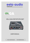
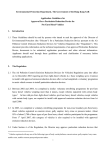
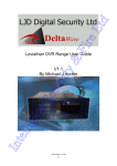
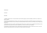
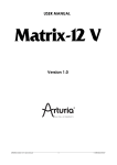
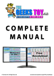
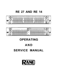
OPERATORS MANUAL
RA 30
REALTIME ANALYZER
-30
METER
-27
-24
-25
-21
-18
-20
-15
-12
-9
-6
-15
-3
-10
+3
+6
-5
+9
+12
0
VU
SPL
SCALE
1
CAL
120
WEIGHT
3
0 dB
PINK
CAL LINE
MIC IN
OFF
AUX
MIC
100
NORM
6
80
A
dB
RTA
METER
25
31.5 40
50
63
80
100 125 160 200 250 315 400 500 630 800
1k 1.25k 1.6k
2k
2.5k 3.15k 4k
5k
6.3k
8k
10k 12.5k 16k 20k
dB
C
RTA
NOISE
OL
-12
RA 30
REALTIME
ANALYZER
+12
SIG
USE RANE
MIC ONLY!
GAIN
SOURCE
CAL MIC
QUICK START
Since the RA 30 does RTA, SPL, and VU all in one, the first-time user can get a little lost. The real Quick Start is in
the Step-by Step Instructions on page Manual-4. This will tell you how to set up the RA 30 for your application. In
addition, read these few tips as a reminder of what you already know:
USE MORE THAN ONE TEST MICROPHONE LOCATION. Speaker dispersion characteristics vary greatly, from
beamy highs to boomy bass bins. While performing the pink noise test, try at least two different test mic locations and average
the two if they differ.
USE ENOUGH PINK NOISE VOLUME TO OVERRIDE BACKGROUND NOISE. There’s no need to run deafening pink noise levels to EQ a system. Just be sure that no LED responds when pink noise is turned off (if they do, background
noise is causing erroneous readings and pink noise should be turned up higher).
MONITORING PROGRAM WITH ANALYZER DISPLAY. Use any Source as an input. You can use this feature to
identify specific feedback points by watching for red LEDs during the performance, then apply EQ exactly where it’s needed
very quickly.
WEAR PARTS: This product contains no wear parts.
Manual-1
FRONT PANEL DESCRIPTION
0 dB
VU METER MODE
-30
METER
-27
-24
-25
-21
-18
-20
-15
-12
-9
-6
-15
-3
-10
0 dB
SPL METER MODE
+3
+6
-5
+9
+12
0
VU
SPL
SCALE
1
CAL
120
WEIGHT
3
0 dB
PINK
RTA
NOISE
80
A
dB
RTA
METER
CAL LINE
MIC IN
OFF
AUX
MIC
100
NORM
6
25
31.5 40
50
63
80
100 125 160 200 250 315 400 500 630 800
1k 1.25k 1.6k
2k
2.5k 3.15k 4k
5k
6.3k
8k
10k 12.5k 16k 20k
dB
C
OL
-12
RA 30
REALTIME
ANALYZER
+12
SIG
USE RANE
MIC ONLY!
GAIN
SOURCE
CAL MIC
Analyzer display LEDs are in a 5 by 30 array (3 color — top & bottom rows are red; middle row is green; in-between
rows are yellow.)
0 dB point is for VU meter mode (SOURCE=LINE IN, GAIN to +4 dBu or -10 dBV, METER/RTA button=METER).
0 dB point is for SPL meter mode (SOURCE=CAL MIC, GAIN to center detent, METER/RTA button=METER). See the
Range indicator , i.e., if the 100 Range LED is on, then the 0 dB LED = 100 dB SPL.
WEIGHT button: provides user-selectable A- or C-weighting in SPL meter mode. The A-curve is a wide bandpass filter
centered at 2.5 kHz, with ~20 dB attenuation at 100 Hz, and ~10 dB attenuation at 20 kHz, therefore it tends to heavily
roll-off the low end, with a more modest effect on high frequencies. It is the inverse of the 30-phon (or 30 dB-SPL) equalloudness curve of Fletcher-Munson. The C-curve is “flat,” but with limited bandwidth, with -3 dB corners of 31.5 Hz and 8
kHz, respectively.
SPL Range indicators: in 120 dB, 100 dB, or 80 dB maximum. The Cal Mic Input auto ranges for optimum operation.
NORM (Normalize) button: sets the 0 dB reference to the maximum level in RTA mode, to help center the display.
Second function: Enables or disables the Peak Hold function in VU meter mode.
Third function: Displays the firmware version when the SOURCE switch is set to OFF. The top row number of LEDs
illuminated is the major version, the bottom row of illuminated LEDs is the minor version.
SCALE button: User selectable ±1, ±3 & ±6 dB per row. For instance, in the ±3 dB position, the yellow LED in each band
lights when signals of that frequency are over +3 dB or below -3 dB, and the red LEDs light at +6 dB and -6 dB.
PINK NOISE button: Engage to activate the built-in pink noise generator. Be sure your system is turned down before engaging this switch to prevent scaring yourself. The LED glows to remind you when pink noise is active.
METER / RTA button: Toggles between the RA 30 performing meter functions, or RTA functions. The corresponding LED
lights to let you know which function is active. The SPL function is only active when CAL MIC is selected and this switch is set
to METER.
햻 OL / SIG indicators: Signal and Overload alerts for the currently selected input. Adjust the GAIN control so the OL light does
not come on.
햽 GAIN control: In SPL meter mode, the RA 30 is calibrated when using Rane's MIC 2 on the CAL MIC Input and the GAIN
control is in center detent position. In VU meter mode, the RA 30 is calibrated to +4 dBu nominal signal (0 dB on VU scale)
when the GAIN control is in center detent position, and calibrated to -10 dBV nominal signal (0 dB on VU scale) when the GAIN
control is in full clockwise position. The gray labels pertain to VU meter mode.
햾 SOURCE selector: A single front panel selector switch chooses which input is fed to the RA 30:
1. OFF: No input selected.
2. CAL MIC: unbalanced, auto gain ranging, XLR-female front panel jack. Uses Rane's MIC 2.
3. LINE IN: balanced/unbalanced ¼" jacks on rear. For mono VU meter function, plug only into the left input.
4. AUX MIC: uncalibrated, balanced, rear panel trim control 15 to 45 dB gain range, rear panel OL LED
햿 CAL MIC Input jack: PLUG ONLY THE RANE MICROPHONE INTO THIS JACK – THE DC VOLTAGE SUPPLIED BY
THIS JACK COULD DAMAGE ANY OTHER MICROPHONE.
Manual-2
REAR PANEL DESCRIPTION
PINK NOISE
OUTPUT
POWER
LINE IN
RA 30
AUX MIC
PIN 2 POSITIVE
PIN 3 NEGATIVE
PIN 1 CHASSIS GROUND
OL
LEVEL
600mA
CLASS 2 EQUIPMENT
RIGHT
LEFT/MONO
MADE IN U.S.A.
RANE CORP.
This device complies with Part 15 of the FCC Rules. Operation is
subject to the following two conditions: (1) this device may not cause
harmful interference, and (2) this device must accept any interference
received, including interference that may cause undesired operation.
GAIN
N108
UNBAL
BAL/UNBAL
BALANCED
POWER input connector: Use only a model RS 1 or other power supply approved by Rane. This unit is supplied with a remote
power supply suitable for connection to this input jack. This is not a telephone jack. The power requirements call for an 18 VAC
center-tapped transformer only. Using any other type of unapproved supply may damage the unit and void the warranty. Two
years parts and labor is worth safeguarding.
Chassis ground point: A #6-32 screw is used for chassis grounding purposes if needed.
PINK NOISE OUTPUT jack: This is an unbalanced ¼" jack which supplies Pink Noise to the sound system.
PINK NOISE LEVEL adjust: Use a 3/16" or smaller screwdriver to adjust the output from the Pink Noise generator to match
the input level requirements of the mixer or other equipment.
LINE INPUT jacks: These are balanced ¼" TRS Inputs, but unbalanced ¼" TS connections will work. When mono VU
metering is desired, only use the LEFT Input. Front panel SOURCE switch must be in LINE IN to activate these jacks.
AUX MIC INPUT jack: A balanced female XLR connector for receiving signals from a low impedance microphone. Pin 2 is
“hot” or (+). Use this jack when you wish to use a microphone other than the one supplied. Front panel SOURCE switch must be
set to AUX MIC for this jack to be active. If your mic requires phantom power, an external supply must be used.
RA 30 CONNECTION
SYSTEM HOOK-UP
Connect the RA 30 into your system as shown below. Plug
the Rane condenser microphone into the front panel MIC
INPUT. CAUTION: Do not plug any other microphone into the
front panel jack: This jack contains a T-power DC voltage
which may be damaging to other microphones.
MIC 2
HI AMP
MIXER
MAIN OUTPUT
EQUALIZER
HI DRIVER
CROSSOVER
LOW AMP
LINE INPUT
POWER
AUX OUTPUT
PINK NOISE
OUTPUT
LINE IN
LOW
DRIVER
RA 30
AUX MIC
PIN 2 POSITIVE
PIN 3 NEGATIVE
PIN 1 CHASSIS GROUND
OL
LEVEL
600mA
CLASS 2 EQUIPMENT
RIGHT
LEFT/MONO
MADE IN U.S.A.
RANE CORP.
This device complies with Part 15 of the FCC Rules. Operation is
subject to the following two conditions: (1) this device may not cause
harmful interference, and (2) this device must accept any interference
received, including interference that may cause undesired operation.
GAIN
N108
UNBAL
BAL/UNBAL
BALANCED
CAL MIC INPUT (FRONT PANEL)
Manual-3
Step by Step Instructions
I. Stereo VU Meter
A. Connect program source to the LINE INPUTS on the rear. If mono operation is desired, connect the mono
program source to the LEFT INPUT.
B. Set the SOURCE switch to LINE IN.
C. Set the GAIN control to the center detent to calibrate the 0 dB mark on the VU scale to +4 dBu.
OR
Set the GAIN control fully clockwise to calibrate the 0 dB mark on the VU scale to -10 dBV.
D. Select the METER mode by pressing the METER/RTA button so the METER LED illuminates.
E. Read the VU level from the display using the VU scale (top row, -30 to +12).
1. The two horizontal yellow rows indicate the VU level. The top row displays the Left Input. The bottom row
displays the Right Input. Levels above +3 dB on the VU scale switch to the red rows.
2. If only the LEFT INPUT is connected, the RIGHT INPUT is internally connected for Mono operation. This
results in the Left and Right displays tracking each other.
3. The VU meter incorporates an instantaneous peak hold function with a 2 second hold time. The peak value is
displayed with a single LED for each channel (transient peaks can often be 6 to 20 dB above the RMS
average value). If the held peak value is greater than +12 dB on
9 dB
CREST FACTOR
the VU scale, the +12 dB LEDs stay illuminated. In this case, the
Input gain can be decreased until the peak value is not “stuck” at
+12 dB. For a calibrated peak measurement, the input gain can be
set to minimum which sets the 0 dB mark on the VU scale to +16
dBu. Example: With the GAIN set to +4 dBu, the display shows a
nominal signal with a 9 dB crest factor.
4. The Peak Hold function is enabled or disabled by pressing the NORM button while in VU mode.
+3
+6
+9
-5
+12
0
VU
SPL
SCALE
1
120
WEIGHT
3
METER
PINK
RTA
NOISE
100
NORM
6
80
dB
dB
A
2.5k 3.15k 4k
5k
6.3k
8k
C
10k 12.5k 16k 20k
II. SPL Meter
A. Connect the Rane MIC 2 to the CAL MIC Input on the front of the unit.
B. Set the SOURCE switch to CAL MIC.
C. Set the GAIN control on the front of the unit to the center detent.
D. Select the METER mode by pressing the METER/RTA button so the METER LED illuminates.
E. Select the desired A- or C-weighting by pressing the WEIGHT button (see WEIGHTING FILTERS, next page).
F. Read the SPL level from the display using the SPL scale (second row
from top).
Example: Reading the middle row of green LEDS from left to right, the
right-most illuminated LED corresponds to -7 dB, the 100 dB LED is
illuminated, and A-weighting was selected (indicated by the A LED), the
A-weighted SPL is 93 dBA.
+3
+6
-5
+9
+12
0
VU
SPL
SCALE
1
120
WEIGHT
3
METER
PINK
RTA
NOISE
100
NORM
6
80
dB
dB
A
2.5k 3.15k 4k
5k
6.3k
8k
C
10k 12.5k 16k 20k
RTA Scales
+0
+0
-10
>+2 dB
-20
-20
-30
dBr
-30
+1-2 dB
-40
-40
-50
-50
-10
dBr
-60
20
50
100
200
500
1k
2k
Hz
SPL mode A-Weighting Curve
5k
10k
20k
-60
20
±1 dB
±1 dB
–1-2 dB
<–2 dB
50
100
200
500
Hz
1k
2k
SPL mode C-Weighting Curve
5k
10k
20k
>+6 dB
+3-6 dB
III. Real Time Analyzer
±3 dB
A. Select the RTA mode by pressing the METER/RTA button so the RTA LED illuminates.
B. Operates on the Input selected by the SOURCE switch: CAL MIC, LINE IN, or AUX MIC. –3-6 dB
Note: When LINE IN is selected, the RTA operates on the mono sum of the Left and Right
<–6 dB
Inputs.
C. Select the scale by pressing the SCALE button, which sets the display in dB relative to the
>+12 dB
center row. See the illustration to the right.
+6-12 dB
D. Press the NORM button to set the maximum band level to 0 dB.
E. Set the desired SCALE and adjust the GAIN control for a centered display.
±6 dB
This just gets you into RTA mode. The following sections describe the whole enchilada.
–6-12 dB
Manual-4
<–12 dB
±3 dB
±6 dB
Alignment Instructions
Since the RA 30 features a unique form of realtime
analyzer, we highly recommend that you read this section
before performing an alignment with pink noise. If you’ve
never used an analyzer before, use these instructions on your
first occasion. You’ll be delighted at how simple it really is.
WEIGHTING FILTERS
Used in SPL mode, the filter “weights” or gives more
attention to certain frequency bands than others. Weighting
filters are a special type of band-limiting filters designed to
compliment the way we hear. Since the ear’s loudness vs.
frequency response is not flat, it is argued, we should not try
to correlate flat frequency vs. loudness measurements with
what we hear.
A-WEIGHT: The A-curve is a wide bandpass filter
centered at 2.5 kHz, with ~20 dB attenuation at 100 Hz, and
~10 dB attenuation at 20 kHz, therefore it tends to heavily
roll-off the low end, with a more modest effect on high
frequencies. It is the inverse of the 30-phon (or 30 dB-SPL)
equal-loudness curve of Fletcher-Munson. A-weighting is
preferred for background music and systems that will be
normally operated at a low level.
C-WEIGHT: The C-curve is “flat,” but with limited
bandwidth, with -3 dB corners of 31.5 Hz and 8 kHz, respectively. C-weighting is preferred for home cinema, live sound,
and systems optimized for operation at full volume.
BACKGROUND NOISE CHECK
Any background noises such as air conditioners, talking,
wild animals, traffic and the like can cause false readings on
the analyzer display if the pink noise volume through the
speakers is not loud enough to drown these noises out.
Before turning on the Pink Noise, set up the RA 30 for RTA
mode with the SCALE set to the 6 dB setting. Turn the GAIN
control on the RA 30 fully clockwise and press the NORM
button: now you’re looking at background noise. Slowly turn
the GAIN control back counter-clockwise until only the
bottom row of red LEDs are on, and no background noise is
showing on the display. If the GAIN control is turned up
(clockwise) from this setting, the background noise will
falsify the readings.
PINK NOISE RUN-UP
Turn down your mixer output controls before switching
on the Pink Noise, so that you don’t detonate your speakers.
Now switch the RA 30 PINK NOISE button ON and turn up
the mixer (and EQ Level) controls slowly until you hear pink
noise through the speaker(s). Increase the Pink Noise Level
until some of the upper row yellow LEDs are on or the OL
LED starts flashing, whichever comes first. There is a Pink
Noise Output Level Adjustment on the rear of the RA 30 —
use a 3/16" screwdriver to vary the amount of Pink Noise to
the mixer if necessary. Proceed to adjust your equalizer with
tips from the following sections. Typically start with 6 dB
SCALE and fine tune as you work down through 3 dB and
then in some instances 1 dB. If the display is too “jumpy,”
then the larger scales work better.
MICROPHONE PLACEMENT
If you are using the analyzer to measure response from a
single predetermined location or “sweet spot,” then the mic
naturally goes right there for testing. For larger audience areas,
perform the pink noise test with at least two different test
microphone locations for each separate channel of EQ. Since
speaker dispersion characteristics can vary greatly, it is desirable
to look at a couple of different areas with the mic to obtain an
average for the entire listening area. If you are using one equalizer channel for both speakers (mono), place the mic in the center
of the left half of the listening area and adjust for green LEDs
with pink noise through the left speaker. Now move the mic to
the center of the right half of the listening area, run pink noise
through the right speaker and observe the analyzer LEDs. For
each frequency that requires a different adjustment than the left
channel, note the original setting of the slider, then adjust it so
that the green LED above it is lit and then note this new slider
position: the final setting should be half-way between these two
slider positions, resulting in an average response for the left and
right channels. If you are running stereo, use two mic locations
for each channel, averaging in the same manner if there are
differences. Analyze one channel at a time.
INITIAL SYSTEM ALIGNMENT
Before using the equalizer for adjustment, use the analyzer to
align other equipment in the system (EQ should always be a last
resort after you’ve corrected response problems everywhere
else). With all EQ sliders flat (centered) adjust the electronic
crossover frequencies and level controls (if used), passive
crossover controls, speaker placement and alignment, etc. to get
as many green LEDs lit as possible on the display. Only after
this is done should you use the equalizer sliders to flatten the
system (see next step).
EQUALIZER SLIDER ADJUSTMENTS
Now adjust each slider up or down as necessary until the
green LED corresponding to the same frequency is lit.
If you can’t get one or more green LEDs lit with their sliders
fully boosted or cut, make a slight adjustment in the Pink Noise
volume or GAIN control to get these bands in the green. Then readjust the remaining sliders. You will also notice that adjusting
one slider may affect the LED readings on the adjacent bands:
this is due to the presence of frequencies half-way between the
two bands, which is affected by both sliders. Not to worry:
simply nudge the adjacent slider until the green LED lights up
again.
FINAL EQUALIZER ADJUSTMENTS
Once the RA 30 is all “greened out”, you’re done with the
pink noise alignment test. Now the speakers are properly
coupled to the specific room and the overall system response is
accurately aligned. This alone will make a great improvement in
most systems, but don't stop at flat necessarily. Now that the
RA 30 has given you a consistent starting point, feel free to
make further slider adjustments during the performance or
sound check to enhance overall sound quality. Fatten the bass,
smooth the mids or sweeten the highs to taste. You will
probably find these adjustments will be consistently set above
or below the Pink Noise test settings the same amount at
Manual-5
each performance; make a note of these further adjustments
to save future tweaking during performances. For example,
you note the pink noise settings and find later that you like to
have 3 dB more boost at 63 Hz for more low-end punch
during the performance. Next time, green out the analyzer
during the pink noise test (get all LEDs green before making
any further adjustment), then immediately bump up the 63
Hz slider 3 dB as indicated by the front panel calibrations so
that you’re tuned up before the show starts (slick, no?).
MONITORING PROGRAM MATERIAL FOR FEEDBACK USING THE DISPLAY
Using RTA mode, and after doing the pink noise test, select
LINE IN to monitor the signal at the RA 30 LINE INPUT jack
on the rear. Adjust the GAIN control so that an occasional upper
yellow LED blinks on during the performance peaks, but no
top row red LEDs come on: you should be in the ±3 dB mode
on the display. If feedback occurs, one or more red lights
show the general feedback frequency area.
TESTING
The RA 30 analyzer/pink noise system is implemented
digitally. The RA 30 analyzer/pink noise system tolerances
do not fade with age, but if you want to verify the system's
performance, the RA 30 contains its own test equipment.
Patch the Pink Noise output to the Left Line Input with a ¼"
TS or TRS patch cord and set the PINK NOISE LEVEL (on
the rear of unit) to maximum. On the front of the unit set the
SOURCE switch to LINE IN. Press the METER/RTA button
to select RTA and turn on the Pink Noise by pressing the
PINK NOISE button. Adjust the GAIN control so that there
is no OL LED indication. Select the 1 dB scale and press the
NORM button. You will see a flat response.
MAIN SPEAKER EQUALIZATION
IMPORTANT NOTES:
1. If your sound system is stereo or multichannel, equalize
each channel individually first, then look at the combined
acoustic output of all channels, making small corrections
as necessary.
2. If you are using a powered mixer, or a mixer that has mic
level inputs only, you will need to reduce the signal level
at the pink noise output. Use a small screwdriver to adjust
the PINK NOISE LEVEL control on the rear chassis so the
Pink Noise Output suits your mixer.
3. An RA 30 can be used as a driver alignment tool (see the AC
22/23/B Owners Manual) as well as EQ adjusting. Drivers
are aligned when maximum level is shown at the crossover frequency on the RA 30 display. It is important to
align drivers either physically or electronically in multiway systems for the best sound. The mic should be at
listener-ear height relative to the center of the driver
stack. If a clear sound is desired in the back of the hall, the
height of the RA 30 mic should be in line with the on-axis
phase response of the speaker stack, perpendicular to the
drivers.
STAGE MONITOR EQUALIZATION
IMPORTANT NOTES:
1. Analyzing and equalizing the monitors provides the most
expedient method to optimize stage monitor sound quality
and reduce feedback problems. The stage mic is connected
to the same mixer as the RA 30. Feedback induced by
specific stage mic/monitor speaker coupling can also be
attenuated by leaving the stage mic turned up and running
up the pink noise level through the monitor speaker until
feedback occurs. Attenuate each feedback frequency, as
indicated by the analyzer display, until the mic/monitor
combination feeds back at two or more frequencies
simultaneously. Usually the final EQ setting will be a
compromise between a good monitor sound that doesn't
get as loud, or a not-so-good monitor sound that gets
louder before feedback.
2. Place the Rane microphone at eye level of the performer
and about six inches off to one side of the stage microphone, in line of sight to the monitor speaker. If the stage
microphone is directly between the Rane mic and monitor
speaker (blocking line of sight), some high frequencies
will be blocked giving a false reading on the analyzer
display.
3. If you are running more than one monitor from a single
equalizer, test each monitor location by running up pink
noise until feedback occurs. The monitor which feeds back
first should be used for the overall EQ adjustments using
pink noise.
4. If maximum SPL before feedback is most important, use
the stage mic only. This arrangement allows the analyzer
to look at the specific relationship between each stage
microphone/speaker combination. Since both the microphone and stage monitor speaker exhibit their own
individual feedback tendencies, the interaction between
the two can cause pronounced feedback problems. This
configuration allows you to flatten or “normalize” this
interaction without actually getting to feedback levels. It
should be noted that this testing procedure favors maximum SPL before feedback and not necessarily optimum
monitor sound quality. This configuration can also be used
for main speaker equalization to optimize system response
for a specific microphone used throughout the system,
such as for choir, orchestral or big band situations where
all program material is picked up through microphones of
the same make and model.
5. Do not attempt to plug a regular microphone directly into
the MIC INPUT. Use the AUX MIC input for other mics.
©Rane Corporation 10802 47th Ave. W., Mukilteo WA 98275-5098 TEL (425)355-6000 FAX (425)347-7757 WEB http://www.rane.com
Manual-6
105553