1
ViewFlex
Version 3.3
User Manual
100299 Rev. J
December 2009
2009 Intelitek Inc.
Catalog #100299 Rev. J
December 2009
Every effort has been made to make this book as complete and accurate as possible. However, no
warranty of suitability, purpose, or fitness is made or implied.
is not liable or
responsible to any person or entity for loss or damage in connection with or stemming from the
use of the application and/or the information contained in this publication.
bears no responsibility for errors that may appear in this publication and retains the
right to make changes to the application and manual without prior notice.
The complete Matrox Inspector User Guide can be viewed and printed from the Matrox
Inspector Help File Inspector_UserGuide.chm included on the ViewFlex software CD.
INTELITEK INC.
444 East Industrial Park Drive
Manchester, NH 03109-5315
Tel: (603) 625-8600
Fax: (603) 625-2137
Website: www.intelitek.com
Table of Contents
1. ViewFlex Installation............................................................................................. 1-1
Unpacking the Equipment................................................................................................ 1-1
System Requirements....................................................................................................... 1-1
Installing the ViewFlex System ....................................................................................... 1-1
Connecting the Software Protection Key................................................................... 1-2
Installing the ViewFlex Software .............................................................................. 1-3
Camera Installation ........................................................................................................ 1-10
Installing the Veo Camera (Windows XP/Vista/7 32 bit OS versions only)........... 1-10
Installing the Logitech® QuickCam®Pro 9000 camera............................................ 1-11
Viewing the ViewFlex Properties.................................................................................. 1-12
ViewFlex.ini File Configuration (for advanced users) .................................................. 1-13
Accessing ViewFlex ...................................................................................................... 1-13
Running the ViewFlex Software.............................................................................. 1-13
Running ViewFlex for SCORBASE USB, USB Pro, ER5, ER7 and ER9 ............. 1-13
2. Software Operation............................................................................................... 2-1
ViewFlex for SCORBASE USB, USB Pro, ER5, ER7 and ER9 Toolbar....................... 2-1
Image Processing Tool............................................................................................... 2-2
Camera (Camera 1 / Camera 2 / ServeCam).............................................................. 2-3
ServeCam Camera Connection (Client Camera only) ............................................. 2-12
Results Table............................................................................................................ 2-13
Vision Commands in SCORBASE.......................................................................... 2-14
Calibration................................................................................................................ 2-18
ViewFlex Toolbar .......................................................................................................... 2-22
ACL Terminal for ViewFlex ................................................................................... 2-22
Abort All .................................................................................................................. 2-27
Go To Position ......................................................................................................... 2-28
Calibration................................................................................................................ 2-30
OpenCIM Device Driver.......................................................................................... 2-33
1
ViewFlex Installation
Unpacking the Equipment
Before installing the equipment, check for signs of shipping damage. If
any damage is evident, contact your freight carrier, and begin appropriate
claims procedures. Make sure you have received all the items listed on the
packing list. If anything is missing, contact your supplier.
System Requirements
Dual Core with 3 GHz processor or higher, with CD drive
At least 512 MB RAM (1 GB for Vista/Windows 7)
A hard drive with at least 100 MB of free disk space (500MB free)
Windows 32 and 64 bit:
Windows XP Professional
Windows Vista (Home Premium/Business/Ultimate editions)
Windows 7 (Home Premium/Professional/Enterprise/Ultimate
editions)
A VGA or better graphics display, minimum 256 colors
A Mouse or other pointing device
USB port
Installing the ViewFlex System
Install the ViewFlex system in the following order:
1. Connect the software protection key. See Connecting the Software
Protection Key on page 1-2.
2. Install the ViewFlex software. See Installing the ViewFlex Software
on page 1-3
ViewFlex v.3.3
1209
1-1
User Manual
3. Install the Camera:
Veo Camera:
Install the Veo camera software. See Installing the Veo
Software on page 1-10
Connect the Veo camera to your computer. See Connecting the
Camera to the Computer on page 1-10
Important:
o Microsoft Windows XP: Do not plug the camera into the
USB port of the computer until after the software
installation.
o Microsoft Windows Vista /Window 7: Plug the camera into
the USB port of the computer before the software is
installed.
Logitech Camera:
Installing the Logitech Software. See Installing the Logitech
Software on page 1-11
Connect the Logitech camera to your computer. See
Connecting the Camera to the Computer on page 1-11
Connecting the Software Protection Key
This step describes how to connect the software protection key, without
this software protection key, the software is programmed to run on a
30-day trial basis.
To connect the software protection key, plug the software protection key
into a USB port in your computer.
Software Protection Key
ViewFlex v.3.3
1209
1-2
User Manual
Installing the ViewFlex Software
To Install the ViewFlex Software
1. Insert the ViewFlex CD-ROM in the drive.
2. The installation procedure should begin to run automatically. If it
does not, select Start | Run, and select install\setup.exe.
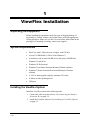
The following window is displayed.
ViewFlex Setup dialog box
You must first install the Image Processing Tool module. Only then
can you install the ViewFlex software.
3. Click on Image Processing Tool. The Matrox Inspector setup will
begin to run.
ViewFlex v.3.3
1209
1-3
User Manual
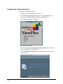
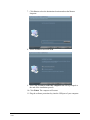
4. Click Next. The License Agreement window is displayed.
5. Select the I accept the terms of the license agreement radio button
and click Next.
6. Click Next to select the destination location for Matrox Imaging
Library.
ViewFlex v.3.3
1209
1-4
User Manual
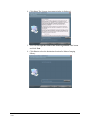
7. Click Next to select the destination location and run the Matrox
Inspector.
8. Select destination and click Next.
9. Select Yes, I want to restart my computer now when prompted at
the end of the installation process.
10. Click Finish. The computer will restart.
11. Plug the software protection key into the USB port of your computer.
ViewFlex v.3.3
1209
1-5
User Manual
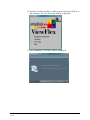
12. Start the ViewFlex installer by clicking on the icon of the CD drive in
My Computer. The ViewFlex Setup window is displayed.
13. Select ViewFlex. A Welcome window is displayed.
ViewFlex v.3.3
1209
1-6
User Manual
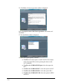
14. Click Next. A License Agreement window is displayed.
Select I accept the terms of the license agreement radio button, and
click Next.
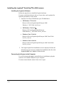
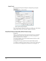
15. The Installation window is displayed.
16. Select the required option, as follows:
ViewFlex v.3.3
1209
ViewFlex: Select this option to install ViewFlex for example,
when using OpenCIM or when operating the robots via the
ACL Controller.
ViewFlex for SCORBASE ER 5plus: Select this option for
ER-5.
ViewFlex for SCORBASE ER 7: Select this option for ER-7.
ViewFlex for SCORBASE ER 9: Select this option ER-9.
ViewFlex for SCORBASE USB: Select this option for ER2U
and ER4u.
1-7
User Manual
ViewFlex for SCORBASE USB PRO : Select this option for
ER 9Pro .
17. Click Next to select the destination location for example for
ViewFlex.
18. Click Next to select the program folder.
19. If you want to create a Desktop shortcut click Yes .
ViewFlex v.3.3
1209
1-8
User Manual
20. The installation is complete.
Select Yes, I want to restart my computer now.
21. Click Finish. The computer will restart.
22. Plug the software protection key into the USB port of your computer.
Note:
If you receive the message: "Could not start ViewFlex” message, perform
the following:
1. Go to Start I Program Files
2. Select Matrox Inspector and right click
3. Select Run as Administrator
4. Wait till Matrox Inspector loads.
5. Close Matrox.
6. Run ViewFlex again.
ViewFlex v.3.3
1209
1-9
User Manual
Camera Installation
After installing the ViewFlex software the next step is to install the
camera.
Installing the Veo Camera (Windows XP/Vista/7 32 bit OS versions
only)
Installing the Veo Software
Follow the steps below to install the Veo software. For additional details
refer to the Veo Velocity Connect User's Guide provided with the camera.
For Vista/Windows 7, the camera must be attached to the computer before
installing ViewFlex.
For Windows XP:
1. Insert the Veo Velocity Connect Installation CD-ROM into your
CD-ROM drive.
2. The Velocity Connect installation screen is displayed. Click Install
and follow the directions on your screen to complete the installation
and refer to the Veo Velocity Connect User's Guide for further details.
For Vista/Windows 7:
(For installing the Veo Software only (without the driver)):
Browse the Veo CD to VeoCreativeStudio\setup.exe
For Windows Vista/Windows 7
1. Insert ViewFlex CD.
2. Browse to Windows: drivers\VISTA_Windows 7
3. Launch the file VeoVista7Driver.exe
Connecting the Camera to the Computer
After installing the Veo camera software, the next step is to connect the
camera to your computer (Windows XP only. in Windows Vista/Windows
7 the camera should have been attached before installation of the
software). You must ensure that the camera's lens cover is open.
To connect the camera to the computer, plug the USB Connector into any
available USB 2.0 port on your computer. A window should appear and
recognize a new device being installed. Once it has been installed, in order
to use the camera, it must be connected to the same USB port it was
installed on.
ViewFlex v.3.3
1209
1-10
User Manual
Installing the Logitech® QuickCam®Pro 9000 camera
Installing the Logitech Software
Follow the steps below to install the Logitech software.
You must verify that the device driver of your video card is updated for
optimum performance of the camera.
1. Insert the ViewFlex CD-ROM into your CD-ROM drive.
XP/Windows 7 32 bit OS:
Browse to Drivers\Logitech QuickCam pro 9000\
Windows_7_XP\32-bit \lws110.exe
XP/Windows 7 64 bit OS:
Browse to Drivers\Logitech QuickCam pro
9000\Windows_7_XP\64-bit\ lws110_x64.exe
Windows Vista 32 bit OS:
Browse to Drivers\Logitech QuickCam pro 9000\Vista\32-bit\
lws110_vista.exe
Windows Vista 64 bit OS:
Browse to Drivers\Logitech QuickCam pro 9000\Vista\64-bit\
lws110_x64.exe
2. The Logitech QuickCam Installation screen is displayed. Follow the
directions on your screen to complete the installation and refer to the
Logitech 9000 User's Guide for further details.
Connecting the Camera to the Computer
You will be instructed during Logitech Software installation to plug the
camera to an available USB port on your computer.
You must ensure that the camera's lens cover is open.
ViewFlex v.3.3
1209
1-11
User Manual
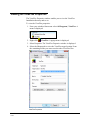
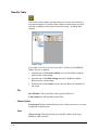
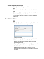
Viewing the ViewFlex Properties
The ViewFlex Properties window enables you to view the ViewFlex
Installation directory and so on.
To view the ViewFlex properties:
1. From your windows Start menu select All Programs | ViewFlex. A
menu is displayed.
2. Right-click
ViewFlex. A popup menu is displayed.
3. Select Properties. The ViewFlex Properties window is displayed.
4. Select the Shortcut tab to view the ViewFlex target location. From
the containing Folder you can access the other ViewFlex files.
ViewFlex Properties
ViewFlex v.3.3
1209
1-12
User Manual
ViewFlex.ini File Configuration
(for advanced users)
The ViewFlex.ini file initializes the ViewFlex software. The ViewFlex.ini
file includes the following options:
1. The directory in which the script files are located (only for the
ViewFlex Device Driver):
[Device Driver Definitions]
ScriptPath= \Vision Script
2. You can choose the controller type – A, B, PC, USB, USBPRO.
[Controller Setting]
Controller=A
(Note: You can choose: ER4, ER4u, ER5, ER9, ER9PRO, ER14,
ER14PRO, viewSV)
RobotType=ER14
3. For configuring the second camera to be either a local camera or a
ServeCam:
IsSecondCameraRemote = YES - camera 2 client servecam
IsSecondCameraRemote = NO - camera 2 local camera
Accessing ViewFlex
Running the ViewFlex Software
To run ViewFlex, from the Start menu,
1. Select Programs | ViewFlex
2. Click on the ViewFlex icon.
Running ViewFlex for SCORBASE USB, USB Pro, ER5, ER7 and ER9
The following explanation refers to all above types of SCORBASE:
To run ViewFlex for SCORBASE
1. In the Start menu, select Programs | ViewFlex for SCORBASE
2. Click on the ViewFlex for SCORBASE icon.
ViewFlex v.3.3
1209
1-13
User Manual
2
Software Operation
ViewFlex for SCORBASE USB,
USB Pro, ER5, ER7 and ER9
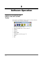
Toolbar
The ViewFlex for SCORBASE Toolbar contains icons that are shortcuts
for selecting certain commands and functions:
ViewFlex for SCORBASE Toolbar
ViewFlex v.3.3
1209
Image Processing Tool; see details on page 2-2
Camera 1
Camera 2
Results Table
Calibration; see details on page 2-18
About
Exit
2-1
User Manual
Image Processing Tool
Open the image-processing tool (Matrox Inspector).
(Refer to the Matrox Inspector Instruction Manual for more
information.)
Matrox Inspector
ViewFlex v.3.3
1209
2-2
User Manual
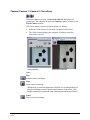
Camera (Camera 1 / Camera 2 / ServeCam)
When two cameras are used, a Select Video Device dialog box will
prompt you. The camera icon opens the Camera (capture) window or the
Client Camera window.
The Client (remote) camera operation operates as follows:
When the Client Camera is activated, it connects to the server.
The Client Camera displays the computer IP address where the
ServeCam is located.
Camera Window
Client Camera Window
Note:
Play
Enables camera streaming
Stop
Stops camera streaming
(When using a resolution higher than 320x240, we recommend that you
stop the streaming to ensure optimum performance of the robot. Even
though streaming is stopped the snap command can still be performed.)
Pause
Pauses camera streaming
ViewFlex v.3.3
1209
2-3
User Manual
Snapshot (ALT + S)
Grabs (captures) a picture and displays it in a frame.
OR
Inserts an updated picture from the ServeCam.
Options (ALT + O)
Opens a dialog box use for video settings and configuration.
Connection (available only in Client Camera)
Enables connection of remote cameras on a network.
Exit
Closes the Camera window.
Camera Options
Camera Options
Always On Top
Checking this box prevents the Camera window from being hidden by
other windows.
Snap Into Current Frame
The captured image will be put into the current frame in the Image
Processing Tool. The part of the image that will be inserted into the frame
depends on the current frame size. If left unchecked, a new frame will be
created each time an image is captured (every Snap).
Configuration
Displays the Video Source Properties dialog box, described in the
following section.
Image Format
Displays the Video Format Properties dialog box, described in the
following section.
Configuration
The configuration is different depending on the camera used.
ViewFlex v.3.3
1209
2-4
User Manual
Logitech® QuickCam® Pro 9000 Configuration
Ensure that you have the Logitech software installed before configuration.
The Video Source Properties dialog box is displayed by pressing the
button, as shown below.
The Video Source Properties window contains the following configuration
tabs:
ViewFlex v.3.3
1209
Zoom/Face Tracking Tab describes how to define your device
settings.
Device Settings Tab, describes how to define your image options,
such as flickering reduction, exposure control, picture quality and
more.
Advanced Tab
2-5
User Manual
Tabs description
Zoom/Face Tracking Tab
The Zoom/Face Tracking tab contains the following options:
Zoom
Adjust the zoom of the camera.
Face Tracking
When enabled for either single or multiple users, the Logitech software
will recognize and track the face(s) in the camera’s view.
ViewFlex v.3.3
1209
2-6
User Manual
Device Settings Tab
The Video Proc Amp tab enables you to define your device settings, by
dragging the relevant sliders such as Brightness, Contrast, Hue Saturation
and more. You can define your default settings as required and then press
Default.
ViewFlex v.3.3
1209
2-7
User Manual
Advanced Tab
The Advanced tab contains the following options:
Exposure
Adjust the exposure control for added customizing.
Gain
Modify the brightness.
Image Mirror
Check either the Mirror Horizontal or Mirror Vertical check boxes to
mirror the video capture in that direction.
Anti Flicker
Select the appropriate radio button for your region to reduce flickering.
Note: These tabs contain the default settings of the camera. For additional
information on the camera configuration, refer to the Logitech®
QuickCam® Pro 9000 User's Guide.
ViewFlex v.3.3
1209
2-8
User Manual
Image Format
The Video Format Properties dialog box is displayed by pressing the
button, as shown below.
Video Format Properties Dialog Box
The Format Properties dialog box enables you to define your video format
setting, such as frame rate, color space, output size and more.
ViewFlex v.3.3
1209
2-9
User Manual
Veo Configuration
The Video Source Properties dialog box is displayed by pressing the
button, as shown below.
The Video Source Properties window contains the following configuration
tabs:
Video Proc Amp Tab describes how to define your device settings.
Image Tab, describes how to define your image options, such as
flickering reduction, exposure control, picture quality and more.
Note: These tabs contain the default settings of the camera. For additional
information on the camera configuration, refer to the Veo (Velocity
Connect) User's Guide.
Tabs description
Video Proc Amp Tab
The Video Proc Amp tab enables you to define your device settings, by
dragging the relevant sliders such as Brightness, Contrast, Hue Saturation
and more. You can define your default settings as required and then press
Default.
ViewFlex v.3.3
1209
2-10
User Manual
Image Tab
The Image tab contains the following options:
Image
Select this check box to flip images horizontally (mirror image).
Flickering reduction
Select the lightening type used in your environment.
Exposure control
Adjust the exposure control for added customizing.
Auto White balance
Adjust the white balance to fine tune the camera to your lightening
conditions.
Decimation mode
Select the Quality or Speed decimation mode.
Note: For USB you must select the Speed decimation mode.
Picture Quality
Move the slider to define the picture quality
Note: For USB, move the slider close to the Speed option.
ViewFlex v.3.3
1209
2-11
User Manual
Image Format
The Video Format Properties dialog box is displayed by pressing the
button, as shown below.
Video Format Properties Dialog Box
The Format Properties dialog box enables you to define your video format
setting, such as frame rate, color space, output size and more.
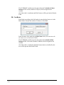
ServeCam Camera Connection (Client Camera only)
Connect to
If there is more than one ServeCam on the network, then you can make a
connection to the specific ServeCam that you want by entering the IP
address of that ServeCam’s computer.
The default IP address is the one that initially appears in the box, which
was automatically detected.
Clicking OK will connect to the ServeCam at the IP address shown.
To configure a second local camera in place of a ServeCam Camera, refer
to ViewFlex.ini File Configuration (for advanced users) on page 1-13.
ViewFlex v.3.3
1209
2-12
User Manual
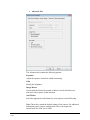
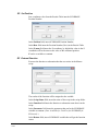
Results Table
The Results Table window is divided into two sections: one section is a
tree representing the ViewFlex folders, and the second section is a table
with the coordinates of the object in the robot world – including blob
features.
Results Table
Every time a new file is saved in one of the ViewFlex for SCORBASE
folders, the tree is updated.
Selecting one of the Pattern Models executes Find Object with the
model on the current image.
Selecting one of the Blob Settings executes Find Blobs with the
Blobset on the current image
Selecting one of the Scripts executes the first function/ subroutine in
the Script.
File
Save Results to file so that they can be opened with Excel.
Load results from file into the Results Table.
Pattern Option
Foreground: Defines whether black pixels or white pixels are to act as the
foreground (or blob) pixels.
View
Always on top: Checking this box prevents this window from being
hidden by other windows.
ViewFlex v.3.3
1209
2-13
User Manual
Vision Commands in SCORBASE
All SCORBASE programming commands are available from the
Command List and are easily compiled into a robot program.
The list shows the two-letter hot-key combinations that allow you to enter
commands from the keyboard.
Many commands open dialog boxes for completing the command line
parameters.
Left: Command list with the Vision Command (ER 4pc, ER-5, ER-7, ER-9).
Right: Vision Command Group (ER 4u).
SN Snap
Captures an image.
FO Find Object
Finds object according to the Pattern Model Name that has been saved in
the Pattern folder. Returns the number of instances of the object.
Enter the name of the model in the Model Name field.
(Note: The name must be the same as it is in the Result Table.)
ViewFlex v.3.3
1209
2-14
User Manual
The SCORBASE variable must be entered into the Variable of Object
Instances. The results (Number of Object) will be assigned to the
variable.
All of the robot’s coordinates and blob features will be put into the Results
Table
FB Find Blobs
Finds blobs according to the blob analysis name that has been save in the
Blobs folder. Returns the number of instances of the Blob.
Enter the name of the model in the Blob Name field. (The name must be
the same as it is in the Results Table.)
The SCORBASE variable must be entered into the Variable of Blob
Instances field. The results (Number of Blobs) will be assigned to the
variable.
All of the robot’s coordinates and blob features that were defined by the
user will be put into the Results Table.
ViewFlex v.3.3
1209
2-15
User Manual
SP Set Position
Sets coordinate value from the Results Table into the SCORBASE
Position Number.
In the Position field, insert SCORBASE Position Number.
In the Row field insert the Position Number (Row) in the Results Table.
In the Z (mm) field insert the Z-coordinate, by default the value in the Zcoordinate will be the same as the value of the calibrated position.
Z can be a variable or constant.
EF External Function
Executes the function or subroutine that the user writes in the Matrox
script.
The results of the function will be assigned to the variable.
In the Script Name field, insert the name of the script in the script folder.
In the Function field insert the function or subroutine name that is in the
script.
In the Parameter field insert the parameter that can be the SCORBASE
variable or constant. (Note: Available for ViewFlex for SCORBASE for
ER-4u only.)
In the Return field, insert SCORBASE variable that will get the function
return.
ViewFlex v.3.3
1209
2-16
User Manual
GV Get Value
Receive a value from any cell in the Results Table.
In the Variable Name field, insert the SCORBASE Variable. The cell
value will be assigned in the variable.
In the Row field insert the cell row in the Results Table.
In the Column field insert the column name in the Results Table. The
Column can be a number or the exact column name.
CT Change Table
Change value in any cell of the Results Table.
In the Row field insert the cell row in the Results Table.
In the Column field insert the column name in the Results Table. The
Column can be a number or the exact column name.
In the Value field insert the SCORBASE variable, or constant that you
want the cell to have.
ViewFlex v.3.3
1209
2-17
User Manual
Calibration
Synchronizing the Vision System and the Robot
To calibrate real-world measurements with the vision system’s system of
pixels, perform the following steps:
1. Execute the HOME routine.
2. Open Client Camera.
Check camera to make sure that the picture is adjusted, clear and free
of distortions.
3. Click the Calibration icon.
4. Using SCORBASE, move robot arm into desired position within the
camera’s field of vision.
5. Using a pen or marker, mark a position on a piece of paper (or on the
coordinate grid) close to the robot and strong enough to be seen in the
camera picture. This position should be aligned with the TCP (tool
center position – the exact center of the robot gripper). This first
position is called Pos 1.
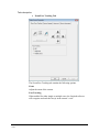
6. Click Record Position 1.
Calibration Step 1 dialog box
7. Along the X-axis only, move the robot to a position on the X-axis
that would be greater (+X) than Pos 1. Take a writing instrument and
mark the position. This second position is called Pos 2.
Click Record Position 2.
ViewFlex v.3.3
1209
2-18
User Manual
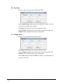
8. Now you will see in the Combo box the distance between the two
positions (Setting Distance) on the X-axis. To achieve the most
accurate measurement, take a ruler and measure the distance between
Pos 1 and Pos 2 by hand.
Change the distance if necessary according to the hand
measurement.
Click Set Distance.
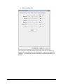
Click Next Step. This opens the Step 2 dialog box.
Calibration Step 2 dialog box
9. If necessary, move robot arm out of the camera’s view.
10. Click Snap in the Step 2 dialog box.
11. You will be able to recognize Pos 1 and Pos 2 in the image.
Click the Pen icon. The Pen icon will start flashing after being
engaged. Your mouse arrow will become a cross.
Click on Pos 1, and then make a dragging motion, using your
mouse, toward Pos 2. This movement represents an increase in
the X-axis. (Shows the direction of increase of the X-axis).
12. Click the Pen icon again. Now the X and Y-axes are set and the
distances are in real-world millimeters.
When you move your mouse along the image, Pos 1 becomes
coordinate 0,0 (center-point) and the directions of X and Y are now the
same as the robot. The movement of the mouse along the axes shows
changes in X and Y.
13. Click Save to save the calibration. Browse to C:\Intelitek\Viewflex
for Scorbase USB\Calibration. Define a file name and click Save.
14. Click OK. Now the Vision System is calibrated and synchronized
with the robot, and all new images will become calibrated.
ViewFlex v.3.3
1209
2-19
User Manual
Opening and Saving Calibration Files
The Configuration Step 2 dialog box enables file management operations.
Save
Saves the calibration. The filename extension is CAL.
Open
Allows you to load backup calibration files. When the OK icon is clicked,
the system is calibrated.
You can configure immediately in the Step 2 tab and open the calibrated
file.
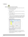
Example of Creating a Pattern Model
1. System must be calibrated, so that real-world measurements
correspond with the vision system’s set of pixels.
2. Open Client Camera.
3. Click the Image Processing Tools icon to open Matrox Inspector.
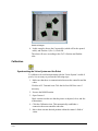
4. For this example, set a cube down within the camera’s field of vision,
so that its edge is parallel to the edge of the Client Camera window.
In order for both the robot gripper and the cube to be set to zero
degrees, the cube must be defined as parallel to the X-axis of the
camera’s world. Subsequently, the robot arm’s rotation will be relative
to this point.
5. In Client Camera, click Snap.
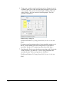
6. Click the ROI (Region of Interest) icon, and outline the perimeter of
the cube that was set.
7. Click the Pattern Matching icon.
Pattern Matching Model Dialog Box
ViewFlex v.3.3
1209
From the Dimension tab, you will see the cube that was
outlined using the ROI icon.
2-20
User Manual
From the Search tab, click All.
From the Angle tab, check Enable Search With Rotate. Then
enter 180 for Delta Negative, and 180 for Delta Positive (this
enables a full 360-degree search).
Click Search. This will build a Measurement Table containing
all the positions of the object relative to Pos 1.
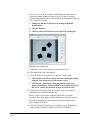
Measurement Table
Searched Images
8. Save the Pattern Matching Model in the Pattern Folder, located in the
ViewFlex for SCORBASE root folder. Ensure that the Pattern dialog
box is selected when saving.
9. Open the Results Table and expand the Pattern Models in the folder
tree. Check that the name you gave is listed in the tree.
10. Use this name when you Find Object.
ViewFlex v.3.3
1209
2-21
User Manual
ViewFlex Toolbar
The ViewFlex Toolbar contains additional icons to the ViewFlex for
SCORBASE USB Toolbar, and some of the icons that are the same
activate certain commands and functions with different functionality than
that of ViewFlex for SCORBASE USB:
ViewFlex Toolbar
Image Processing Tool
Camera 1
Camera 2
ACL Terminal (for ViewFlex)
Abort All
Go Position
Calibration
OpenCIM Device Driver
About
Exit
ACL Terminal for ViewFlex
ACL, Advanced Control Language, is an advanced, multi-tasking robotic
programming language.
The ACL Terminal for ViewFlex is the software interface that provides
access to the controller from a PC, and provides functions needed to
configure, program and operate the robot system.
ACL Terminal for ViewFlex
ViewFlex v.3.3
1209
2-22
User Manual
Save
Saves a listing of all user programs, variables and positions in one file.
The files are in ACL format (.acl).
Download
Downloads data from a user-backup file in the host computer to the
controller. (Does not erase or modify existing programs.)
Abort All
Immediately aborts all running programs and stops movement of axes.
On-Line/Off-Line
Opens/closes the communications port.
ON-CON
Enables servo control for all axes, a specified group of axes, or a single
axis.
OFF-COFF
Disables servo control for all axes, a specified group of axes, or a single
axis.
Home
Drives all robot axes to their home position.
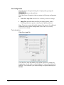
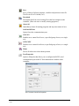
Port Properties
Opens a dialog box that allows you to configure the RS232 serial
communication port in the PC that communicates with the robot
controller:
ACL Terminal CommPort Properties
ViewFlex v.3.3
1209
2-23
User Manual
ACL ViewFlex String Commands
The ViewFlex String Commands are written as:
Print / Println “%ViewFlex string commands %”
ViewFlex helps you make applications that combine vision and robot
guiding that will use the ACL language for controlling and executing
robot tasks.
ViewFlex Variable
Vision functions are written in Visual Basic (VB) script. The vision script
will operate the vision task. To synchronize the vision and robot tasks,
there is the Global Variable (VF). After executing the Vision Function or
subroutine, the VF value will be 1 (VF=1).
SNAP
Format:
%SNAP%
Description:
Will capture an image from the camera and put it into
the Image Processing Tool.
Examples:
PRINTLN "%SNAP%"
RUN
Format:
%RUN prog%
Description:
Where: prog is the name of a function or subroutine in
the script. The function returns the ACL command back
to the controller.
Examples:
PRINTLN "%RUN PROG%"
This executes the function or subroutine in the open VB
script file. If you execute the function, the results will be
sent to the controller.
The script must be loaded before it can be executed from
the ACL.
ViewFlex v.3.3
1209
2-24
User Manual
SETPOS
Format:
%SETPOS Position, Table index, Table name, Z(mm)%
Description:
Where:
Position is a defined robot position.
Table index is a position of the object in a measurement
table that was found in the image after searching. The
reserve word ALL means that if a Position is the name of
a vector all the positions in the table will be set.
Table name is the name of the measurement table. If
omitted, it means Current table.
Z is the value of the Cartesian coordinate Z in
millimeters.
Examples:
PRINTLN “%SETPOS pos,1, , 60%”
Position pos receives the coordinate value of position 1
in the Current measurement Table, while the coordinate
value of Z is 60 mm.
PRINTLN “%SETPOS pv[4],3,table1 , 80%”
Position pv[4] receives the coordinate value of position 3
in the measurement table named table1, while the
coordinate value of Z is 80 mm.
PRINTLN “%SETPOS pv,ALL,table2 , 80%”
Vector pv receives the coordinate values of ALL
positions in the measurement table named table2, while
the coordinate value of Z is 80 mm.
ViewFlex v.3.3
1209
2-25
User Manual
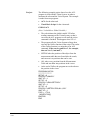
Project:
The following example project shows how the ACL
program is used with the Vision System, in order to
automate the robot and the Vision System. The example
is made from two programs:
ACL: for the robot task
Visual Basic Script: for the vision task.
GOPOS.ACL
(Note: N should be a Global Variable.)
The code initiates the global variable VF before
sending comments to the Vision System, so that it
can cause the ACL program to wait until the vision
command is finished. This happens when VF is 1.
The program tells the Vision System to Snap, then
executes the GetPos function in the script. The results
of the GetPos function is a string that is an ACL
command. If the search results are 3, for example,
then set N to 3 (“set n=3”).
SETPOS takes the position of the object from the
measurement table that was found after the search,
and converts it to positions that can be sent.
ALL takes every position from the Measurement
Table and sets them into positions in the vector.
At the end of GoPos, the program moves the robot to
the position in the vector.
PROGRAM GOPOS
*********************
SET VF = 0
PRINTLN "%SNAP%"
WAIT VF = 1
SET VF = 0
PRINTLN "%RUN GETPOS%"
WAIT VF = 1
SET VF = 0
PRINTLN "%SETPOS POS,ALL,,60%"
WAIT VF = 1
FOR I = 1 TO N
MOVED POS[I]
ENDFOR
END
ViewFlex v.3.3
1209
2-26
User Manual
GETPOS.BAS
In order for the Run command to work, the script
must be loaded.
The model for the object whose script will be
searched should also be loaded.
When the script will be executed, a measurement
table with the positions will be created. The script
will also send a command that initiates a sign of the
number of objects that were found.
Function GETPOS()As String
I_IMAGE1$ = Insptr.ImgGetCur
Insptr.ImgSetCurrent I_IMAGE1$, R_Def$,
ALL_BANDS
Insptr.ImgConvertType(TO_8U)
Insptr.MeasNew()
M_X_MOD$=Insptr.PatGetCur
Insptr.PatSetCur M_X_MOD$
x=Insptr.PatFind
Insptr.ImgClose
Num=Insptr.MeasGetLastID
GETPOS="SET N=" + CStr(num)
End Function
Abort All
Format:
[Ctrl] + A
Description:
Immediately aborts all running programs and stops
movement of axes.
[Ctrl] + A is the fastest software method for stopping
program execution and halting movement of all axes. It
can be used at any moment, even while entering another
command, in order to instantly halt programs and axes.
This command is entered from keyboard, but does not
require [Enter] for execution.
ViewFlex v.3.3
1209
2-27
User Manual
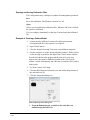
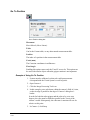
Go To Position
Go to Position dialog box
Movement
Move/MoveL (Move Linear).
Table
Can be the Current table, or any other named measurement table.
Position
The index of a position in the measurement table.
Z-axis (mm)
The Cartesian coordinates in millimeters.
Fixed Angle
Enabling this option causes only the X and Y axes to be. This option can
be used with circular objects when the gripper rotation is not important.
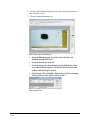
Example of Using Go To Position
1. System must be calibrated, so that real-world measurements
correspond with the Vision System’s world of pixels.
2. Open Camera 1.
3. Click the Image Processing Tool icon.
4. In this example, put a cube down within the camera’s field of vision,
so that its edge is parallel to the edge of Camera 1 dialog box’s
border.
In order for both the robot gripper and the cube to be set to zero
degrees, the cube must be defined as parallel to the X-axis of the
camera’s world. Subsequently, the robot arm’s rotation will now be
relative to this point.
5. In Camera 1, click Snap.
ViewFlex v.3.3
1209
2-28
User Manual
6. Click the ROI (Region of Interest) icon, and outline the perimeter of
the cube that was set.
7. Click the Pattern Matching icon.
Pattern Matching Model dialog box
From the Dimension tab, you will see the cube that was
outlined using the ROI icon.
From the Search tab, click All.
From the Angle tab, check Enable Search With Rotate. Then
enter 180 for Delta Negative, and 180 for Delta Positive (this
enables a full 360-degree search).
Click Search. This will build a Measurement Table containing
all the positions of the object relative to Pos 1.
Measurement Table
ViewFlex v.3.3
1209
2-29
User Manual
Searched Images
8. In this example, choose the Current table (which will be the opened
table), and Position 1 (Pos 1). Click OK.
The robot will move according to the Go To Position and find the
cube.
Calibration
Synchronizing the Vision System and the Robot
To calibrate real-world measurements with the Vision System’s world of
pixels, it is necessary to perform the following steps:
1. Make sure that there is communication between the controller and the
robot.
Click the ACL Terminal icon. Click the On-Line/Off-Line icon if
necessary.
2. Execute the HOME routine.
3. Open Camera 1.
Check camera to make sure that the picture is adjusted, clear, and free
of distortions.
4. Click the Calibration icon. This automatically establishes a
connection between controller and robot.
5. Move robot arm into desired position within the camera’s field of
vision.
ViewFlex v.3.3
1209
2-30
User Manual
6. Using a pen or marker, mark a position on a piece of paper (or on the
coordinate grid) close to the robot and strong enough to be seen in the
camera picture. This position should be aligned with the TCP (tool
center position – the exact center of the robot gripper). This first
position is called Pos 1.
Calibration Step 1 dialog box
Click Record Position 1. (If using Controller-B, be sure it is in Auto
Mode.)
If trying to record a position produces a beep sound the reason may be
that the Teach Pendant has not been changed from Teach Mode to
Auto Mode. (In the ACL Terminal, type Auto, then click Enter.)
7. Only along the X-axis, move the robot to a position on the X-axis that
would be greater (+X) than Pos 1. Take a writing instrument and
mark the position. This second position is called Pos 2.
Click Record Position 2. (If using Controller-B, be sure it is in Auto
Mode.)
ViewFlex v.3.3
1209
2-31
User Manual
8. Now you will see in the Combo box the distance between the two
positions (Setting Distance) on the X-axis. To achieve the most
accurate measurement, take a ruler and measure the distance between
Pos 1 and Pos 2 by hand.
Change the distance if necessary according to the hand
measurement.
Click Set Distance.
Click Next Step. This will take you to the Step 2 dialog box.
Calibration Step 2 dialog box
9. If necessary, move robot arm out of the camera’s view.
10. Click Snap in the Step 2 dialog box.
11. You will be able to recognize Pos 1 and Pos 2 in the image.
Click the Pen icon. The Pen icon will start flashing after being
engaged. Your mouse arrow will become a cross.
Click on Pos 1, then make a dragging motion, using your
mouse, toward Pos 2. This movement represents an increase in
the X-axis. (shows the direction of increase of the X-axis).
12. Click the Pen icon again. Now the X and Y-axes are set and the
distances are in real-world millimeters.
When you move your mouse along the image, Pos 1 becomes
coordinate 0,0 (center-point), and the directions of X and Y are now
the same as the robot. The movement of the mouse along the axes
shows changes in X and Y.
13. Click OK. Now the Vision System is calibrated and synchronized
with the robot, and all new images will become calibrated.
ViewFlex v.3.3
1209
2-32
User Manual
Opening and Saving Calibration Files
The Configuration Step 2 dialog box enables file management operations.
Save
The Save icon saves the calibration. The extension of the files is .CAL.
Open
The Open icon will allow you to load backup calibration files. When the
OK icon is clicked, the system is calibrated.
You can configure immediately in the Step 2 dialog box and open the
calibrated file.
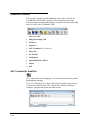
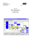
OpenCIM Device Driver
The ViewFlex Device Driver interfaces between the OpenCIM network
and the Vision Machine System as a quality control device.
ViewFlex Device Driver
Each quality control test is defined as a separate process in the Machine
Definition module. The quality control test consists of three parts:
ViewFlex v.3.3
1209
File: The File is the Script File (.bas) that contains the Program
(Function) to be executed.
Program: The Program is the Function from the File that returns the
results of the quality control process to the OpenCIM Manager as
Pass/Fail or Error.
Fail %: Simulates test results (only in Simulation Mode) by
determining the Pass/Fail according to the percentage of failure that
was input.
2-33
User Manual
The ViewFlex Device Driver performs the following functions:
Activates a test on the Vision Machine System.
Receives status messages from the Vision Machine System and from
the OpenCIM Manager. (OpenCIM Messages dialog title in the
ViewFlex.)
Allows you to test and debug the Vision Machine process.
Emulates the Vision Machine System in Simulation mode.
ViewFlex Properties
ViewFlex.ini
Be sure to update the script-path to the folder where the scripts files are.
An example of where the directory that the script files are located in:
[Device Driver Definitions]
ScriptPath= C:\Users\Public\Documents\Intelitek\OpenCIM\Projects\LIB\viewflex
ViewFlex v.3.3
1209
2-34
User Manual
Operation Modes
The Operation Mode lets you to define the control mode ViewFlex Device
Driver is running in:
On-Line
On-Line mode the ViewFlex Device Driver waits for the commands from
the OpenCIM Manager, and then Snap, Load Script, Execute Program
Script, and Send Results.
Manual
Manual Mode allows you to test the OpenCIM Manager and manually
simulate conditions of Fail and Pass.
The following are activated only in Manual Mode, after a request from the
OpenCIM Manager:
Send Pass
Sends pass to the Manager.
Send Fail
Sends fail to the Manager.
Simulation
Simulation Mode allows you to simulate test results by determining the
Pass/Fail according to the percentage of failure that was input to the
OpenCIM Manager.
Debug
The Debug Mode allows you to debug every step of the script. This is
made for testing the script before it will be run online.
The following are activated only in Debug mode:
Open File lets you load the script.
Run Script icon executes the script that has been chosen.
Step-By-Step icon lets you to execute each command line of the script
individually.
ViewFlex v.3.3
1209
2-35
User Manual
Example of Script for Pass/Fail Test
The following script is an example for testing Pass/Fail Models. A Model
refers to the pattern for which you are searching, and the image for which
it is extracted.
The following program will try to find the “x” object by using the x-model
(x.mod). If found, Fail is sent (QCR=“Fail”). If not found, then it will try
to find the “v” object. If found, Pass is sent (QCR=“Pass”). If neither is
found, Error is sent (QCR=“Error”).
For more information on the commands, refer to Inspector’s online help.
Function QCR() As String
Dim x As Integer
I_IMAGE1$ = Insptr.ImgGetCur
Insptr.ImgSetCurrent I_IMAGE1$, R_Def$, ALL_BANDS
' X.mod is a Model Search of object for Fail sign
M_X_MOD$ =
Insptr.PatLoad("C:\Users\Public\Documents\Intelitek\OpenCIM\Projects\\MICROC
IM\WS3\ViewFlex\X.mod")
Insptr.PatSetCur M_X_MOD$
Insptr.ImgConvertType(TO_8U)
Insptr.MeasNew()
x=Insptr.PatFind
If x=1 Then
QCR="Fail"
Else
' V.mod is a Model Search of object for Pass sign
M_Y_MOD$ =
Insptr.PatLoad("C:\Users\Public\Documents\Intelitek\OpenCIM\Projects\MICROCI
M\WS3\ViewFlex\V.mod")
Insptr.PatSetCur M_Y_MOD$
x=Insptr.PatFind
If x=1 Then
QCR="Pass"
Else
QCR="Error"
End If
End If
Insptr.PatClose
Insptr.ImgClose
Insptr.MeasClose
Insptr.CloseAll
End Function
ViewFlex v.3.3
1209
2-36
User Manual