1
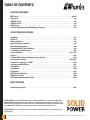
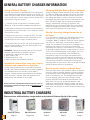
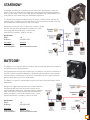
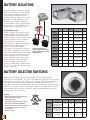
MARINE SOLUTIONS
www.charlesindustries.com
TABLE OF CONTENTS
BATTERY CHARGERS
IMC Series . . . . . . . . . . . . . . . . . . . . . . . . . . . . . . . . . . . . . . . . . . . . . . . . . . . . . . . . . . . . . . . .m3-m4
HQ Series . . . . . . . . . . . . . . . . . . . . . . . . . . . . . . . . . . . . . . . . . . . . . . . . . . . . . . . . . . . . . . . . . . . .m3
5000 SP Series . . . . . . . . . . . . . . . . . . . . . . . . . . . . . . . . . . . . . . . . . . . . . . . . . . . . . . . . . . . . . . . .m4
2000 SP Series . . . . . . . . . . . . . . . . . . . . . . . . . . . . . . . . . . . . . . . . . . . . . . . . . . . . . . . . . . . . . . . .m4
9000 Series . . . . . . . . . . . . . . . . . . . . . . . . . . . . . . . . . . . . . . . . . . . . . . . . . . . . . . . . . . . . . . . . . . .m5
General Information Regarding Battery Chargers . . . . . . . . . . . . . . . . . . . . . . . . . . . . . . . . . . .m6
AC/DC POWER SOLUTIONS
StartNow . . . . . . . . . . . . . . . . . . . . . . . . . . . . . . . . . . . . . . . . . . . . . . . . . . . . . . . . . . . . . . . . . . . . .m7
BattCom . . . . . . . . . . . . . . . . . . . . . . . . . . . . . . . . . . . . . . . . . . . . . . . . . . . . . . . . . . . . . . . . . . . . .m7
Battery Isolators . . . . . . . . . . . . . . . . . . . . . . . . . . . . . . . . . . . . . . . . . . . . . . . . . . . . . . . . . . . . . .m8
Battery Selector Switches . . . . . . . . . . . . . . . . . . . . . . . . . . . . . . . . . . . . . . . . . . . . . . . . . . . . . .m8
Multi-Stage Regulators . . . . . . . . . . . . . . . . . . . . . . . . . . . . . . . . . . . . . . . . . . . . . . . . . . . . . . . . .m9
Continuous Duty Power Supplies . . . . . . . . . . . . . . . . . . . . . . . . . . . . . . . . . . . . . . . . . . . . . . . .m9
C-Power Surge Suppressors . . . . . . . . . . . . . . . . . . . . . . . . . . . . . . . . . . . . . . . . . . . . . . . . . . .m10
Power Inverters . . . . . . . . . . . . . . . . . . . . . . . . . . . . . . . . . . . . . . . . . . . . . . . . . . . . . . . . . .m11-m12
Smart-Y . . . . . . . . . . . . . . . . . . . . . . . . . . . . . . . . . . . . . . . . . . . . . . . . . . . . . . . . . . . . . . . . . . . . .m13
C-Phone Ship to Shore Communications System . . . . . . . . . . . . . . . . . . . . . . . . . . . . . . . . . .m13
Shore Power Cabling . . . . . . . . . . . . . . . . . . . . . . . . . . . . . . . . . . . . . . . . . . . . . . . . . . . . .m14-m15
Isolation Transformers / ISOG2 . . . . . . . . . . . . . . . . . . . . . . . . . . . . . . . . . . . . . . . . . . . . . . . . .m16
Iso-Boosts with SoftStart . . . . . . . . . . . . . . . . . . . . . . . . . . . . . . . . . . . . . . . . . . . . . . . . . . . . . .m17
SmartBoost . . . . . . . . . . . . . . . . . . . . . . . . . . . . . . . . . . . . . . . . . . . . . . . . . . . . . . . . . . . . . . . . . .m17
ShoreBoost . . . . . . . . . . . . . . . . . . . . . . . . . . . . . . . . . . . . . . . . . . . . . . . . . . . . . . . . . . . . . . . . . .m18
DockBoost . . . . . . . . . . . . . . . . . . . . . . . . . . . . . . . . . . . . . . . . . . . . . . . . . . . . . . . . . . . . . . . . . .m18
A/B Selector Switches . . . . . . . . . . . . . . . . . . . . . . . . . . . . . . . . . . . . . . . . . . . . . . . . . . . . . . . .m19
AC Master Control . . . . . . . . . . . . . . . . . . . . . . . . . . . . . . . . . . . . . . . . . . . . . . . . . . . . . . . . . . . .m19
PM3 Power Management System . . . . . . . . . . . . . . . . . . . . . . . . . . . . . . . . . . . . . . . . . . . . . . .m20
BOAT STORAGE
Boat Storage Stands . . . . . . . . . . . . . . . . . . . . . . . . . . . . . . . . . . . . . . . . . . . . . . . . . . . . . . . . . .m21
SOLID POWER is more than a marketing slogan at Charles Industries, it’s a corporate philosophy.
SOLID POWER is embodied in our strict adherence to manufacturing standards of excellence; our
dedication to supplying your electronics with safe, reliable power; our passion for innovation; and
our commitment to the industry’s best customer service both before and after the sale.
SOLID POWER is who we are, what we do, and what we strive to provide to our customers each
and every day.
m2
Charles Industries, Ltd. • 5600 Apollo Drive • Rolling Meadows, IL 60008 • (847) 806-6300 • www.charlesindustries.com
HQ BATTERY CHARGERS
ABS listed and certified Marine Battery Chargers that meet USCG
requirements for megayacht and workboat fleets around the world.
The HQ Series offers a rugged battery charger and power supply all in one unit.
Many government, military, homeland security, megayachts, and commercial
marine vessels are required to meet ABS standards on all new construction over
150 gross tons and/or vessels over 90 meters. The HQ Series delivers full
compliance for battery chargers. Models feature 120/240VAC input and 12VDC
(25-105 amp) or 24VDC (15-65 amp) output. 5-year limited manufacturer’s warranty,
made in the USA.
Specifications
• Agency approvals: ABS listed and certified, meets USCG (10B) and ABYC (A-31) requirements
• LED indicator pilot lamp
• Quick disconnect on/off switch on front cover
• Separate voltmeter and ammeter
• Internal failure alarm (ready), customer to provide indicator
• Multi-bank (3), multi-stage (bulk, absorption and float) battery charger
• Ability to work as power supply
• Voltage and current limiting ability
• Thermal, over-current, ignition and reverse-polarity protected
• Input and output fusing
• Constructed with heavy-duty, corrosion resistant, UL recognized materials
• Designed to run cool, quite and EMI/RFI interference free
• Temperature compensation - built for optimal performance in a variety of ambient temperatures
• AC input: 120VAC or 240VAC models
• DC output: 12VDC/25-105 amp or 24VDC/15-65 amp
• 50/60Hz for international and U.S. applications
• Drip shield (necessary) included
• ABS Type Approved
12 Volt Models
24 Volt Models
Amperage 120 VAC · 50/60 Hz 220 VAC · 50/60 Hz Dimensions Weight
Amperage 120 VAC · 50/60 Hz 220 VAC · 50/60 Hz Dimensions Weight
25
9Q-12255HQ-A
9Q-12255HQI-A
8.125”x9”x4.75”
8 lbs.
15
9Q-24155HQ-A
—
8.125”x9”x3.75”
8 lbs.
35
9Q-12355HQ-A
9Q-12355HQI-A
8.125”x9”x4.75”
8 lbs.
25
9Q-24255HQ-A
9Q-24255HQI-A
13.25”x9”x3.75”
10 lbs.
45
9Q-12455HQ-A
9Q-12455HQI-A
13.25”x9”x4.75”
10 lbs.
35
9Q-24355HQ-A
9Q-24355HQI-A
15.25”x9”x3.75”
11 lbs.
55
9Q-12555HQ-A
9Q-12555HQI-A
15.25”x9”x4.75”
11 lbs.
45
9Q-24455HQ-A
9Q-24455HQI-A
15.25”x9”x3.75”
11 lbs.
65
9Q-12655HQ-A
9Q-12655HQI-A
21.5”x9”x4.75”
16 lbs.
55
9Q-24555HQ-A
9Q-24555HQI-A
21.5”x9”x4.75”
17 lbs.
65
9Q-24655HQ-A
9Q-24655HQI-A
21.5”x9”x4.75”
17 lbs.
85
9Q-12855HQ-A
9Q-12855HQI-A
21.5”x9”x4.75”
17 lbs.
105
9Q-121055HQ-A
9Q-121055HQI-A
21.5”x9”x4.75”
17 lbs.
SALES SUPPORT
TECHNICAL SUPPORT
(Monday - Friday, 8:00 AM - 5:00 PM CST)
(Monday - Friday, 8:00 AM - 5:00 PM CST)
Phone:
Fax:
Email:
Web:
Phone:
Fax:
Email:
Web:
(847) 806-6300
(847) 806-6653
[email protected]
www.charlesindustries.com
(800) 830-6523 or (217) 932-2317
(217) 932-2473
[email protected]
www.charlesindustries.com
(includes Owner’s Manual archive)
m3
5000 SP BATTERY CHARGERS
5000 SP Series chargers feature a battery type selector switch, allowing you to
charge Lead Acid, Gel or AGM batteries. They are tested by Marine UL for
safety and durability against impact, vibration, temperature and shock. 3-stage
charging with temperature compensation (30 Amp and greater models) delivers
the greatest charge when the battery is most able to accept it, prevents overcharging and extends battery life. Up to 3 battery banks can be simultaneously
restored. These units also act as a power supply providing constant voltage to
DC components such as bilge pumps or DC lighting. A convenient design
features an easy-to-read DC ammeter, access to terminal connections and
fuses and exterior slots for easy mounting. Safety features include ignition and
reverse-polarity protection. These units are designed with corrosion-resistant
components, a heavy-duty enclosure and heat sink for durability in the marine
environment. Units run cool and quiet, without generating significant RFI or EMI
interference. All units are Marine UL listed and are designed for low emissions.
Dripshield included. 5-year limited manufacturer’s warranty, made in the USA.
Specifications
Battery Types:
Charge Voltage Bulk:
Charge Voltage Float:
DC Output Voltage:
AC Input Voltage:
Frequency:
Temperature Range:
Safety Features:
Housing:
Dimensions (12V):
12 Volt Models
Amperage 120 VAC · 50/60 Hz 220 VAC · 50/60 Hz
10
93-12105SP-A
15
93-12155SP-A
N/A
N/A
20
93-12205SP-A
9C-12205SPI-A
30
93-12305SP-A
9C-12305SPI-A
Lead Acid, Gel or AGM
40
93-12405SP-A
9C-12405SPI-A
14.5V / 14.2V / 14.2V
50
93-12505SP-A
9C-12505SPI-A
13.4V / 13.4V / 13.35V
60
93-12605SP-A
9C-12605SPI-A
12V or 24V
80
93-12805SP-A
9C-12805SPI-A
95-140VAC or 200-240VAC
100
93-121005SP-A
9C-121005SPI-A
50Hz or 60Hz
-20ºC to 55ºC
24 Volt Models
Thermal, over current, reverse polarity and ignition protected
Amperage 120 VAC · 50/60 Hz 220 VAC · 50/60 Hz
Anodized Aluminum
10
93-24105SP-A
N/A
10-20 amp: 8.125”x9.625”x3.75”, 30 amp: 10.5”x9.625”x3.75”,
20
93-24205SP-A
9C-24205SPI-A
40 amp: 13.25”x9.625”x3.75”, 50-60 amp: 15.25”x9.625”x3.75”,
30
93-24305SP-A
9C-24305SPI-A
80-100 amp: 21.5”x9.625”x3.825” (see website for 24V model dimensions)
40
93-24405SP-A
9C-24405SPI-A
21-104589-0
Replacement Dripshield for 10 to 40 amp 5000 SP Series Battery Chargers
50
93-24505SP-A
9C-24505SPI-A
93-TEMPPROBE-A
Temperature Probe for 30, 80 & 100 amp 12 volt models and 50 & 100 amp 24 volt models
60
93-24605SP-A
9C-24605SPI-A
2000 SP BATTERY CHARGERS
An excellent choice for value-priced, high-performance DC charging, the 2000
SP Series units include a battery type selector switch allowing you to charge
Lead Acid, Gel or AGM batteries. 3-stage charging delivers the greatest charge
when the battery is most able to accept it, preventing overcharging and
extending battery life. Units restore up to 3 banks simultaneously. Other
features include the ability to act as a power supply, ignition and reversepolarity protected, easy-to-read DC ammeter, corrosion-resistant components
and housing, and a heavy-duty heat sink design. Exterior slots allow for easy
mounting. 2-year limited manufacturer’s warranty, made in the USA.
Specifications
Battery Types:
Charge Voltage Bulk:
Charge Voltage Float:
DC Output Voltage:
AC Input Voltage:
Frequency:
Temperature Range:
Safety Features:
Housing:
Dimensions:
m4
12 Volt Models
Lead Acid, Gel or AGM
14.5V / 14.2V / 14.2V
13.4V / 13.4V / 13.35V
12V
95-140VAC
50Hz or 60Hz
-20ºC to 55ºC
Thermal, over current, reverse polarity and ignition protected
Anodized Aluminum
10-30 amp: 8.125”x9.625”x3.75”, 40 amp: 10.5”x9.625”x3.75”,
50 amp: 13.25”x9.625”x3.75”
Amperage
120 VAC · 50/60 Hz
10
93-12102SP-A
15
93-12152SP-A
20
93-12202SP-A
30
93-12302SP-A
40
93-12402SP-A
50
93-12502SP-A
9000 SP BATTERY CHARGERS
These marine UL listed chargers use self-regulating ferroresonant transformers
devoid of any complicated switching circuits to charge up to three battery banks
simultaneously. Built with rugged stainless steel enclosures and UL recognized,
high-quality components to withstand the marine environment. Accurately charge
lead-acid batteries only. Features include an easy-to-read ammeter to indicate rate of
charge and ignition-protected components for safety. 12, 24 or 32VDC. Dripshield
included. 5-year limited manufacturer’s warranty, made in the USA.
Specifications
Battery Types:
Battery Banks:
Charge Voltage:
DC Output Voltage:
AC Input Voltage:
Frequency:
Temperature Range:
Safety Features:
Housing:
Lead Acid
15 Amp = 2, All Others = 3
Single stage 13.8V finish on 12VDC,
27.6V finish on 24VDC
12V, 24V or 32V
95-140VAC
60Hz
-25ºC to 55ºC
Thermal, over current, reverse polarity
and ignition protected
Stainless Steel
12 Volt Models
24 Volt Models
Amperage
120 VAC · 60 Hz
Amperage
120 VAC · 60 Hz
15
CI1215A
20
CI2420A
20
CI1220A
30
CI2430A
30
CI1230A
40
CI2440A
40
CI1240A
32 Volt Models
Amperage
120 VAC · 60 Hz
30
CI3230A
40
CI3240A
Dimensions: 12V 15-20 amp: 6.25”x7.5”x9.5”;
12V 30-40 amp, 24V 20-30 amp:
8.75”x9”x11.5”; 24V 40 amp, 32V 30-40 amp:
10.25”x11.5”x13”
10 REASONS TO BUY A CHARLES
C-CHARGER® BATTERY CHARGER
either lead-acid, gel or AGM batteries. With Charles C-Chargers, you will
not need to continuously replace batteries. C-Chargers are designed to
accurately charge the batteries, neither under-charging nor over-charging,
thus prolonging battery life.
1. Fully automatic recharging
Batteries must optimally perform in the marine environment, yet they are
susceptible to a vast number of ills, including misuse. If used incorrectly,
they will begin to degenerate and battery cells may be lost. Charles
C-Chargers automatically recharge batteries to 100% with accurate
current and voltage regulation. In larger units, (30 amp - 100 amp models)
automatic temperature compensation guarantees fast, safe and efficient
charging.
6. Marine UL Listed
Charles 5000 SP Series High-Frequency and 9000 Series Ferroresonant
Battery Chargers are Marine UL Listed. These chargers have passed
Underwriters Laboratories’ stringent tests including shock, vibration,
temperature and corrosion. Marine UL auditors randomly conduct
inspections of our manufacturing processes to ensure that Charles
products continue to be built to marine UL standards. This continuous
testing and inspection ensures that you are receiving the best quality
product.
2. Ability to simultaneously recharge and act as a power supply
C-Chargers function as both a battery charger and a power supply that
automatically boosts the 12/24V circuit to full capacity when input voltage
is low. Thus, DC loads such as lights or automatic bilge pumps can run off
of the battery charger if necessary.
7. Low emissions
All models are designed for low emissions to prevent electrical interference.
Thus, the chargers will not significantly interfere with onboard equipment.
3. Designed for safety
C-Chargers feature thermal, over-current, reverse polarity and ignition
protection. Units 30 Amps and above have built-in temperature
compensation. These safety features safeguard your power systems and
prevent expensive damage to onboard equipment.
4. Built to withstand harsh marine environments
All Charles C-Chargers feature UL recognized, corrosion-resistant
components and housings. All PC boards are conformal coated to
stabilize hydrolytes and withstand the marine environment.
5. One charger for any battery type
Charles’ new 5000 SP and 2000 SP Battery Chargers feature a battery
type selector switch. This feature allows the boater to set the charger for
8. Made in the USA
Charles is a vertically integrated company, manufacturing components
and finished goods in the midwestern United States. The employees of
our Casey, Illinois manufacturing plant take great pride in the quality of
their workmanship.
9. Industry’s best warranties
Charles’ 5000 SP series and 9000 series battery chargers feature a
5-year warranty that sets the standard for marine battery chargers.
10. Designed to improve battery longevity and save you money
C-Chargers are designed to accurately charge batteries, neither over nor
under charging them, to keep battery cells healthy. All electronic chargers
feature isolated outputs, eliminating the need for a battery isolator and
protecting one battery from discharging into another.
m5
GENERAL BATTERY CHARGER INFORMATION
Sizing a Battery Charger
Charging Multiple Battery Banks (outputs):
The size of the battery charger depends on the amp-hours
of the batteries and the loads the charger must supply. The
loads must also include the DC loads for which the charger
must provide when in power supply mode. A simple rule of
thumb when sizing your charger:
Charles C-Chargers include isolation at each output. 2000
SP, 5000 SP, 9000 & HQ chargers will look for the battery
that is the most depleted and direct power into that unit
first. When that battery's power is level with the others,
the charger will share power with all of the batteries in the
bank. The IMC Charger uses a round-robin approach to
charging. All batteries will charge in sequence, with
additional time give to batteries with lower power levels.
Charles C-Chargers are constructed in a such a way that
each output can handle the full current rating.
1. Total the number of amp-hours in the battery bank.
(Group 24, 27 & 31 batteries are @100-120 amp-hours)
2. Most battery companies recommend that the batteries
be discharged no more than 50%. Thus, divide the number
of amp-hours by 50%.
3. Decide how much time, in number of hours, you want
the recovery of the batteries to take. Divide 50% of the
total amp-hours by the number of recovery hours.
4. The final number you are left with is the amperage of the
battery charger needed to bring your battery bank to full
charge in the desired time.
EXAMPLE: A boater has a battery bank of four Group 27
batteries and would like to recharge in 8 hours.
• 4 Batteries x 120 amp-hours each = 480
• 50% of 480 = 240
• Divided by 8 hours = 30
• Battery charger size should be _> 30 amps
Installation Information: wire size, torque,
distance and connection to batteries
Charles recommends that you consult ABYC (American
Boat & Yacht Council) standards for information regarding
the installation and use of onboard, marine battery
chargers. Charles torque recommendations are included
within all owner’s manuals. Wire size depends on the
distance from the batteries to the charger.
Charles recommends consulting ABYC standards for direction on the use
and installation of batteries and chargers. Please visit www.abycinc.org for
more information.
Should I leave my charger turned on at
all times?
If you are using a C-Charger you should leave the charger
on at all times. The output voltage of the electronic
C-Chargers (2000 SP, 5000 SP, HQ & IMC series chargers)
will move to a "float" stage, or maintenance stage, of
charge. This provides a minimal amount of voltage to the
battery(s) that creates a very low level of heat while
maintaining the "ampacity" of the battery(s). Ferroresonant,
single stage chargers will reach a peak voltage of 13.8V at
10% of the full rated amperage of the charger; this is the
low end of the unit's operating curve considered the
maintenance phase. Do not forget that batteries are in
constant use, even for minimal loads such as automatic
bilge pumps and DC lighting. If a small amount of charge is
not continually provided to the batteries while they are
supplying power to these items, they may deeply discharge
having an adverse effect on the batteries.
How long does battery recharge take?
There are many factors that can either shorten or lengthen
the time it takes to recharge batteries, including condition
of the batteries, battery temperature, depth of discharge,
loads on the batteries, etc. The average recommended
time for recharge is 8 hours if the C-Charger is sized
properly. (See ABYC standards for load calculation and
sizing info.) This time can be adjusted based on user
preference, understanding of battery upkeep, the use of
temperature compensation, charging profiles and nominal
loads which can enhance or restrict the performance of the
charger.
INDUSTRIAL BATTERY CHARGERS
Please see these additional battery charger models on the Industrial Solutions flipside of this catalog:
m6
INcharger Series
EB & EP Series
AA Series
AE Series
CI Series
Page i3
Pages i3-i4
Page i5
Page i6
Page i7
STARTNOW™
A great day of boating is a complete success when your engine starts to take you
home! There is no worse end to a boating trip than discovering a discharged battery
when you are ready to call it a day. With the new StartNow from Charles Marine, you
never have to worry about facing this unpleasant experience.
The StartNow microprocessor allows the main battery to drain without draining the
reserve battery. StartNow automatically detects if the main battery voltage is too low
and activates the reserve battery to start your engine.
Recharging is automatic from an alternator or battery charger
and the microprocessor guarantees the battery will never
overcharge and always be ready. 1-year limited
manufacturer’s warranty, made in the USA.
Specifications
Weight:
Dimensions:
1 lb.
3"H x 4"W x 2.5"D
Part Number
93-STARTNOW-A
93-STARTNWRMT-A
Description
StartNow
Optional Remote Dash Indicator
BATTCOM™
The BattCom™ is a high-tech battery combiner that automatically allows the charging of
two batteries from a single alternator.
Using advanced technology and complex logic, the BattCom monitors the alternator of
the boat. Once an operational alternator is detected, both batteries are automatically
combined. When the alternator is turned off, the batteries are once again isolated to
prevent power draining from the other battery.
The BattCom is ideal for multiple battery systems and as an automatic battery switch
replacement.
Designed for rugged environments, the compact BattCom
incorporates 280 amp heavy duty relay contacts and is
100% sealed and waterproof. Corrosion resistant stainless
steel studs and an impact resistant ABS case make this
battery combiner a must for any serious boater. 1-year
limited manufacturer’s warranty, made in the USA.
Specifications
Weight:
Dimensions:
1 lb.
3"H x 4"W x 2.5"D
Part Number
93-BATTCOM-A
93-STARTNWRMT-A
Description
BattCom - 12VDC
Optional Remote Dash Indicator
m7
BATTERY ISOLATORS
All Charles Battery Isolators are ignition
protected. They feature a heat chamber
design, protective boots on heavy-duty
5/16” battery and alternator studs,
corrosion-resistant casings, are compact
and easy to install. Either leg of the
Charles Battery Isolator handles the
entire alternator output amperage rather
than a portion of the rated load. 1-year
limited warranty, made in the USA.
Using a Battery Isolator
When charging multiple battery banks,
Charles suggests connecting a battery
isolator between the charger and the
batteries. Battery isolators isolate charge
current and stop it from recirculating,
thus preventing one battery from
discharging into a lesser charged battery.
When properly installed within the
system, the alternator remains
connected to the batteries at all times,
eliminating the possibility of damage to
the diodes. Charles Battery Isolators are
built to be robust, with either leg of the
isolator handling the entire alternator
output amperage rather than a portion
of the rated load. Please note that by
inserting a battery isolator into the
system, a voltage drop of approximately
0.7 to 1.5 DC, depending on the charge
current, will occur.
+
+
-
+
-
12V DC Charging System
including (from top to bottom):
battery charger, battery isolator
and battery bank.
Product No.
Amps
Alternators
Battery
Banks
Dimensions
Weight
93-BI70/1-A
70
1
1
4.5”x4.875”x3.625”
2 lbs.
93-BI70/2-A
70
1
2
4.5”x4.875”x3.625”
2 lbs.
93-BI70/3-A
70
1
3
4.5”x4.875”x3.625”
2 lbs.
93-BI702/3-A
70
2
3
7.5”x4.875”x3.625”
2 lbs.
93-BI90/2-A
90
1
2
6.5”x4.875”x3.625”
3.5 lbs.
93-BI130/2-A
130
1
2
6.5”x4.875”x3.625”
4 lbs.
93-BI160/2-A
160
1
2
7.5”x4.875”x3.625”
4.6 lbs.
93-BI160/3-A
160
1
3
9.75”x4.875”x3.625”
5.5 lbs.
93-BI190/2-A
190
1
2
9.75”x4.875”x3.625”
4.7 lbs.
93-BI190/3-A
190
1
3
10.5”x4.875”x3.625”
5.5 lbs.
93-BI250/2-A
250
1
2
10.5”x4.875”x4.125”
5.8 lbs.
BATTERY SELECTOR SWITCHES
Charles Battery Selector Switches allow boaters to choose between any
combination of two batteries. The switch with alternator disconnect is for use when
the batteries are shut off but the engine is still running. The alternator disconnect
eliminates possible damage to the alternator, a valuable assurance that the
alternator is protected. All Charles Battery Selector Switches are ignition protected,
Marine UL Listed and meet US Coast Guard and ABYC standards. All switches are
manufactured with heavy-duty contacts for optimal, reliable performance. 2-year
limited manufacturer’s warranty.
Features
• White polyethylene color with black knob
• Heavy-duty contacts ensure
optimal performance
• Lightweight, compact and easy to install
• Screw caps provide clean installation
• Designed with corrosion-resistant materials
for years of trouble-free use in marine
environments
• Marine UL Listed
m8
Product No.
Description
Continuous
Amps
Intermittent
Amps
Dimensions
Weight
93-BS002AD-A
Four position
(2 battery) switch with
Alternator Disconnect
230
345
5.5” dia., 2.6” deep
2 lbs.
93-BS002-A
Four position (2 battery)
switch without Alternator
Disconnect
230
345
5.5” dia., 2.6” deep
2 lbs.
93-BS001-A
On/Off Switch
230
345
5.5” dia., 2.6” deep
2 lbs.
MULTI-STAGE REGULATORS
Charles Multi-Stage Regulators are designed to
control the power of the alternator output and
maintain the proper battery charging voltage
regardless of the engine speed. The charge
effect of the alternator depends solely on the
electronic three-stage regulator. These units
have been designed for use with a wide variety
of type-P alternators. 2-year limited manufacturer’s
warranty, made in the USA.
+
Features
• Utilizes microprocessor-controlled technology to regulate
the alternator output
• Multi-stage charging: 1st current is limited by the alternator,
2nd absorption stage current begins to fall off, 3rd float or
maintenance stage. Charging profile is adjustable
• Ignition protected
• Smart overload protection
• Temperature compensation
• LED charge state indicators
• Corrosion-resistant components
• Marine UL Listed
+
-
-
+
12V Alternator/Regulator
System including (from top to bottom):
multi-stage regulator, alternator,
battery isolator and battery bank.
Product No.
Description
Dimensions
Weight
93-12PREG-C
12V Multi-Stage Regulator
7.25”x7.5”x2.75”
1.5 lbs.
93-24PREG-B
24V Multi-Stage Regulator
7.25”x7.5”x2.75”
1.5 lbs.
CONTINUOUS DUTY POWER SUPPLIES
Onboard equipment such as single side-band radios, radar rectifiers, halogen and other
lighting systems require a constant DC voltage to operate, yet the source does not have
to be batteries. Power supplies may be used to run this equipment. They provide a
constant 14.4 volts DC and are lightweight, compact, clean, quiet and easy to install.
They are able to accept variances in frequency, 45 to 65 Hz, and variances in AC input
(120 VAC units: 90 to 135 VAC, 220 VAC units: 180 to 270 VAC) without degrading
output. 1-year limited manufacturer’s warranty, made in the USA.
Technical Information
• Constructed with a heavy-duty heat sink, anodized aluminum enclosure and corrosion-resistant
components for years of trouble free use in the marine environment
• Provides a constant 14.4 volts DC
• Compact, lightweight
Product No.
AC Input
Volts
DC Output
Volts
Amps
Dimensions
Weight
93-PS1230-A
120
13.65
30
3.7”x9.5”x10.5”
9 lbs.
93-PS1240-A
120
13.65
40
3.7”x9.5”x13.25”
10 lbs.
93-PS1260-A
120
13.65
60
3.7”x9.5”x15.25”
12 lbs.
93-PS1280-A
120
13.65
80
3.7”x9.5”x21.5”
17 lbs.
93-PS2430-A
120
25.5
30
3.7”x9.5”x15.25”
10 lbs.
93-PS2460-A
120
25.5
60
3.7”x9.5”x21.5”
17 lbs.
9C-PS2430-A
220
25.5
30
3.7”x9.5”x15.25”
10 lbs.
m9
C-POWER® SURGE SUPPRESSORS
Charles has designed surge protection devices specifically for onboard marine use.
These products protect valuable AC and DC systems from power surges and spikes.
An EMI suppressor unit is also available to protect against DC transients created by
trim tab pumps. 2-year limited manufacturer’s warranty, made in the USA.
Features
• Utilize Metal Oxide Varistor (MOV) technology
• Low impedance construction requires little energy
to function
• Thermal and short circuit fusing for safety
• Corrosion-resistant, aluminum housing
• Solid-state diagnostics
• Ignition protected
Special AC Unit Features
• All mode protection
• Suppression of surge current up to 90,000 amps
Special DC Unit Features
• Bi-directional
• 5 nanosecond response time
EMI Suppressor
In some cases, the hydraulic solenoid controlled
pump utilized in trim tabs can create DC
transients. To protect equipment from these
transients, Charles has designed the EMI
Suppressor. This cost-competitive, compact unit
stops transients in their tracks before they can
affect onboard equipment.
AC Units
EMI
Product No.
93-SS30-A
93-SS50/100-A
93-SS12-A
93-SS24-A
93-SPRSR-A
Amperage
30 amps
50/100 amps
—
—
—
VAC/VDC
120 VAC
120/240 VAC
12 VDC
24 VDC
12 or 24 VDC
Dimensions
7.5”x9”x5.25”
7.5”x9”x5.25”
7.5”x9”x5.25”
7.5”x9”x5.25”
6.75”x5”x2.38”
Weight
3.55 lbs.
3.55 lbs.
3.55 lbs.
3.55 lbs.
2.5 lbs.
A LOOK AT CHARLES’ CASEY, IL
MANUFACTURING CENTER
When you see the “Made in the USA” stamp on a Charles Industries’
battery charger, isolation transformer, cord set or any other product, take
a moment to consider exactly what that means. For the city of Casey,
Illinois, that means jobs for US workers. It’s a testament to the pride and
dedication of those workers as they strive to provide you with the
highest quality, most reliable and safest marine products available
anywhere.
Day in and day out at our Marine Products Manufacturing Center in
Casey, our experienced workforce puts into practice our commitment to
quality. More than 90% of the facility’s employees have 5 or more years
experience at Charles. Our employees are some of the most
knowledgeable, talented, and dedicated workers in the industry, and their
manufacturing experience translates into superiorly made AC and DC
electrical equipment that is both rugged and reliable.
MADE IN THE
Our Casey facility, along with Charles three other US
manufacturing centers, is certified to ISO 9001:2008
international quality management system standards.
Charles employs environmentally responsible manufacturing methods
and gives back to the communities it is a part of through educational
programs and endowments. Charles Marine Group is also proud to
support charities such as the Shake-A-Leg Sailing Program for disabled
and disadvantage participants, and the Judd Goldman Adaptive Sailing
Foundation.
m10
DC Units
DC-to-AC POWER INVERTERS
Charles Power Inverters convert 12 and 24 volt DC battery power into 120/240
60Hz AC power that can be used to operate onboard equipment and appliances.
Now, regardless of the size of the vessel, it is possible to run a notebook
computer, microwave, blender, television or other desired equipment. Inverters
can also be a viable alternative to turning on a generator. They produce less noise
and no fumes, and require less power to run.
True Sinewave vs. Quasi/Modified Sinewave: which inverter is right for your application?
Inverters utilize two types of technology, true sinewave or quasi/modified
sinewave. Each has its pros and cons; whether one is better than the other
depends on the application. If the unit is used to start equipment that demands a
strong surge when turned on, to start up a motor for example (refrigerators,
dishwashers, TVs, etc.), a quasi-sinewave inverter is a better choice. If the unit is
required to power laptops, radar or items that need very clean power (items with
visible screens for example), a true sinewave inverter is ideal. In addition, there are
differences among the quality of quasi-sinewave inverters. Modified waves look
like steps moving up and then down the wave. The larger the number of steps,
the cleaner the power. Charles Quasi/Modified Sinewave Series Inverters make
more than 19,000 steps to complete a single sinewave, providing very clean
quasi-sinewave power.
True Sinewaveform
Recommended for computers, radar and
other equipment with visible screens.
True Sinewave Inverter
True Sinewave Inverter/Charger
Quasi/Modified Sinewave
Recommended for motor-driven and
high-surge startup equipment.
Effect of using an inverter on batteries
Although earlier inverter technologies used up battery power quickly, new highfrequency inverters are much more efficient. Charles inverters utilize cutting-edge
technology that does not waste energy. Household appliances and onboard lights
manufactured in recent years are more economical than their 12 or 24 DC volt
equivalents. What does that mean to you? Batteries will last longer. Charles
inverters are equipped with a specialized circuit that maintains a high output on
partial loads and offers a “sleep cycle” mode, using up little power from the
batteries while still supplying AC power. This mode will continue to operate low
wattage equipment such as VCRs, radios and clocks.
Inverters as an efficient alternative to generators
Generators are noisy, costly and consume expensive fuel. Inverters are quiet and
do not produce the exhaust fumes as do generators. They do not consume gas or
diesel fuel and can provide up to 4.5 kilowatts of power. Inverters supply power
sparingly, only when needed; generators must run continuously. The bottom line:
increased fuel economy, fewer hours running the engine, no fumes and hours of
quiet onboard power.
How many hours of power will the batteries supply?
Batteries serve as an energy source for 12 or 24 volt equipment as well as the DC
power of the inverter. The larger the battery, measured in number of amp-hours,
the longer it will last. One must also factor in the loads on the battery to accurately
calculate both battery power required and the number of hours the battery will
supply that power. Boats normally have DC loads such as lights, pumps, etc. as
well as AC loads such as daily appliances, navigation equipment, etc. Please
consult the ABYC standards for further information about load calculation.
Quasi/Modified Sinewave Inverter
Five reasons to choose Charles’
“Solid Power” DC-to-AC Power Inverters
1. Built to last
Features include corrosion-resistant
enclosures, conformal coated PC boards,
and heavy-duty transformers.
2. Safety and testing
Many units are UL Listed, all units are
thoroughly tested prior to shipment. All units
feature overload, short-circuit, reverse polarity,
over temperature, and under-voltage protection.
3. Easy to install and use
Enclosures provide the flexibility to mount in a
variety of positions.
4. Power efficiency
Charles inverters are built to provide optimal
AC power when it is needed. A “sleep cycle”
mode provides minimal power without
draining energy out of the batteries.
5. Suitable for any electrical system
Charles inverters can be installed on any
vessel with available battery power. To
estimate inverter needs, see page m12.
m11
POWER INVERTER / BATTERY CHARGER COMBO
Charles inverter/battery charger combinations save space by sharing electronics and transformers. While connected to the generator or shore-power, the inverter/ chargers recharge
the batteries quickly and efficiently. Status LEDs indicate the batteries’ state of charge.
The unit automatically controls the charger or inverter functions. While shore power is
connected, the battery charger is turned on. When shore power is disconnected, the unit
automatically switches to the inverter mode, supplying the electrical system with AC power.
POWER INVERTER SPECIFICATIONS CHART
True Sinewave
Model
93-ACP1210
Function
93-ACP1215
93-ACP1220
Quasi/Modified Sinewave
93-ACP1221C
93-ACP1232
93-ACP1226
93-ACP1236
DC-to-AC power inverter—supplies AC power to electronics, appliances and other equipment from user-provided batteries
Output
Wave Form
TRUE
TRUE
TRUE
TRUE
TRUE
TRUE
QUASI-SINE
QUASI-SINE
Technology
High
Frequency
High
Frequency
Line
Frequency
Line
Frequency
Line
Frequency
Line
Frequency
Line
Frequency
Line
Frequency
Low Voltage
Shut Off
10.5 VDC
10.5 VDC
10.5 VDC
8.0 VDC
10.5 VDC
10.5 VDC
10.5 VDC
10.5 VDC
High Voltage
Shut Off
15 VDC
15 VDC
16.6 VDC
17 VDC
16.6 VDC
16.6 VDC
16 VDC
16 VDC
Load Sensor
Activated
10+ Watt
Load
10+ Watt
Load
5+ Watt
Load
Selectable
5+ Watt
Load
Selectable
5+ Watt
Load
5+ Watt
Load
DC Input
Voltage
10.5-15 VDC
10.5-15 VDC
10.5-16.6 VDC
10.5-17 VDC
10.5-17 VDC
10.5-16.6 VDC
10.5-16 VDC
10.5-16 VDC
AC Output
Voltage
120V±3%
120V±3%
120V±5%
120V±5%
120V±5%
120V±5%
120V±5%
120V±5%
Surge AC Amps
(3 seconds)
16
16.7
25.6
53.3
43.7
53.3
65
80
Continuous
Wattage
1000
1500
2000
2100
3200
3200
2600
3600
Frequency
60 Hz
60 Hz
60 Hz
60 Hz
60 Hz
60 Hz
60 Hz
60 Hz
Stand-by/
Sleep Mode
Yes
Yes
Yes
No
Yes
No
Yes
Yes
Weight
15.1 lbs.
15.5 lbs.
48 lbs.
66 lbs.
70 lbs.
66 lbs.
74 lbs.
88 lbs.
Dimensions
4.1”x10.8”x15.4”
4.1”x10.8”x15.4”
4.1”x10.8”x15.4”
8.3”x18.5”x13.7”
4.1”x10.8”x15.4”
8.3”x18.5”x13.7”
8.4”x17.5”x14”
8.4”x17.5”x14”
LED Indicators
Low Battery Warning & Shutdown, Over-Temp, Overload, Inverter On/Off
Protection Features
Overload, Short Circuit, Reverse Polarity, Over Temperature, Over Load, Over/Under Voltage
Warranty
2-Years
2-Years
2-Years
2-Years
2-Years
2-Years
2-Years
2-Years
UL, cUL Listed
No
No
Yes
Yes
Yes
Yes
Yes
Yes
Inverter/Charger
Option
N/A
N/A
N/A
Inverter/Charger
Only (100 Amp)
N/A
Inverter/Charger
Only (100 Amp)
93-ACP1226C
120 Amp Charger
93-ACP1236C
120 Amp Charger
Notes
Part numbers in orange are inverter/charger combination units. Remote controls available. Units that are not UL or cUL Listed are built to meet UL, cUL standards.
Please note that other wattages—as well as 220VAC, 50 Hz models—are available. Please call for further details.
INVERTER SIZING GUIDE
m12
93-ACP1232C
APPLIANCE
Lamp
Stereo System
VCR / DVD Player
Laptop / Desktop Computer
13” Television
Small Kitchen Items
3/8” Drill
19” Television
Blender / Coffee Maker
Small Microwave
REQ. WATTS
150
200
200
500
500
500
1000
1000
1000
1000
APPLIANCE
Dehumidifier
Ice Maker
Food Processor
Hairdryer
27” Television
3.5 cu. in. Refrigerator
Microwave/Oven
Vacuum Cleaner
Toaster Oven
21 cu. ft. Refrigerator
APPLICATIONS
REQ. WATTS
1000-1500
1000-1500
1000-1500
1000-2000
1500
1500
1500
2000
2000
2000
SAIL BOATS
RECREATIONAL VEHICLES
POWER BOATS
CAMPERS
SMART-Y™ ADAPTERS
Charles’ patented Smart-Y Adapters enable boaters to reliably
double available shore voltage. Designed for long life, the
Smart-Y eliminates the potential for shock hazard when one
leg is disconnected; both legs must be plugged into the
power source before current will flow. Smart-Y products will
provide years of trouble-free use in the marine environment.
Manufacturer’s limited lifetime warranty, made in the USA.
Features
• Plug & cover constructed of UL-recognized thermoplastic vinyl, providing
a water-tight waterproof seal
• Nickel-plated phosphor bronze, corrosion-resistant contact blades
• NEMA 4 enclosure protects electrical contacts and relay network
• Molded integral strain relief in the 50 amp plug reduces moisture and
minimizes cracking & breakage
• Glass-filled nylon and polycarbonate internal components maintain a high
degree of electrical insulation
Product No.
Connectors
Color
93-SMTY50-A
Female: 50amp-125/250V twist lock
Male:
(2) 30amp-125V twist lock
Yellow
93-SMTY50W-A
Female: 50amp-125/250V twist lock
Male:
(2) 30amp-125V twist lock
White
93-SMTY100-C
Female: 100amp-125/250V twist lock
Male:
(2) 50amp-125/250V twist lock
White
C-PHONE SHIP-TO-SHORE
COMMUNICATIONS SYSTEM
Full Feature System
The C-Phone system offers the boat owner a wide variety
of convenient, useful functions, including an intercom,
hailer, security alarm and fog horn.
Modular
The system can be expanded from 4 to 12 stations by
adding modules of 4 stations at a time. Thus, the boat
owner is not forced to buy more or less than the boat
requires.
Easy to Install
Only two conductors (tip and ring) connect the main
control to each station. No special wiring, operates on
12, 24 or 32 volts DC.
Economical
The C-Phone is competitively priced. When compared
feature-to-feature the C-Phone offers far more than
expensive PBX alternatives.
Ability to interface with cellular and satellite options
The C-Phone can easily interface with cellular and satellite
options creating a full feature communications system.
Features
• Intercom
• Paging, Security Alarm and Fog Horn when used with the 8 ohm,
30 watt Hailer
• Handset-controlled hailer volume
• Distinctive ring identification, rings differ between land, intercom and
cellular calls
• Selective privacy ringing
• Microprocessor controlled with solid-state components
• Designed specifically for marine, onboard use – tested to withstand
shock, humidity, vibration, temperature and dust
• 1-year warranty, made in the USA
Product No.
Description
93-940400-B
4 Station Master Control Unit
93-EK4000-B
4 Station Expansion Module—add up to 2 modules for a total of 12 stations
97-001685-C
Handset Kit
m13
SHORE POWER CABLING SOLUTIONS
C-Cable® Hull Inlets
E
LIFETIM Y!
NT
A
R
WAR
MADE IN THE
C-Cable® Accessories
E
LIFETIM Y!
NT
A
R
WAR
30 Amp
125 Volt
I30MPF
I30
I30MPF
I30MP
I30MP-AC
I30MAC
30amp-125V inlet, interior switch replacement
30amp-125V inlet, white polycarbonate w/flip cover
30amp-125V inlet, white polycarbonate, threaded cover
30amp-125V inlet, white poly., w/chrome ABS threaded cover
30amp-125V inlet, chrome plated ABS, threaded cover
50 Amp
125/250 Volt
I50MBC
I50MBC-I
I50MP
I50HMBC
I50HMBC-I
I50HMP
I30MP
I30MAC
I30MP-AC
30C
30C
30CW
30CR
I50MBC
I50MP
I50HMBC
I50HMP
50amp-125V inlet, chrome plated brass
50amp-International inlet, chrome plated brass
50amp-125V inlet, white polycarbonate
50amp-125/250V inlet, chrome plated brass
50amp-International 220V inlet, chrome plated brass
50amp-125/250V inlet, white polycarbonate
30amp cover, yellow
30amp cover, white
30amp yellow cover, blue ring
30CR
30F1
30F1
30M1
30RB
30amp-125V female connector
30amp-125V male plug
30amp ring, blue
50C
50C
50CR
50CW
50CRW
50CRW
50amp cover, yellow
50amp yellow cover, blue ring
50amp cover, white
50amp white cover, blue ring
50F1
50M1
50F1
50HF1
50amp-125V female connector
50amp-125V male plug
100 Amp
125/250 Volt
I100HMP
I100HMP
100amp-125/250V single-phase inlet, white polycarbonate
Phone &
Cable TV
IPHTVMPF
IPHTVMP
IPHTVMP-AC
IPHTVMAC
m14
100HF1
100HF1
100HM1
IPHTVMP
IPHTVVP-AC
IPHTVMAC
Phone/TV inlet, white polycarbonate w/flip cover
Phone/TV inlet, white polycarbonate threaded cover
Phone/TV inlet, white poly., w/chrome ABS threaded cover
Phone/TV inlet, chrome plated ABS, threaded cover
100amp-125/250V, single-phase female connector for use with inlet only
100amp-125/250V, single-phase male plug
PHC
PHC
PHF1
PHM1
100HM1
PHF1
Phone plug/connector cover boot, yellow
Female phone connector
Male phone plug
PHM1
SHORE POWER CABLING SOLUTIONS
IME
C-Cable® Cord-Sets LWIFAETRRANTY!
30M1
P30
R30
COUP30B
ENDCAPB
R30
1530PCM35L
15 to 30amp-125V, 35’ molded cable (yellow only)
30PCM25L
30amp-125V, 25’ molded cable
30PCM35L
30amp-125V, 35’ molded cable
30PCM50L
30amp-125V, 50’ molded cable
30PCM75L
30amp-125V, 75’ molded cable
Standard cord-sets are yellow in color. Cord-sets are available in white.
To order in white, add “W” to end of the part number (i.e. 30PCM25LW).
30amp grey cover plate for R30 receptacle
30amp-125V NEMA l5-30R receptacle
30amp watertight connecting coupler assembly, blue
Watertight threaded end cap, blue
50M1
50HM1
P50
R50
50HF1
50HM1
R50H
P30
R50
R50H
30PCM25L
30PCM35L
30PCM50L
30PCM75L
P50
50amp grey cover plate for R50 and R50H receptacles
50amp-125V NEMA L5-50R receptacle
50amp-125/250V female connector
50amp-125/250V male plug
50amp-125/250V NEMA L6-50R receptacle
50PC50
50PC50
50amp-125V, 50’ cable cord-set with heavy-duty connectors
50HPC25
50amp-125/250V, 25’ cable cord-set with heady-duty connectors
50HPC50
50amp-125/250V, 50’ cable cord-set with heady-duty connectors
Standard cord-sets are yellow in color. Cord-sets are available in white.
To order in white, add “W” to end of the part number (i.e. 50HPC25W).
Hand Adapters
Model #
A1530
A3015
Connector (Female)
15amp-125V straight blade
30amp-125V twist lock
Plug (Male)
30amp-125V twist lock
15amp-125V straight blade
Standard hand adapters are yellow in color. Hand adapters are available in white.
To order in white, add “W” to end of the part number (i.e. A1530W).
Straight Adapters
A1530S
A3015S
A3050S
A3050HS
A5030S
A50H30S
A100H50HS/A
15amp-125V straight blade
30amp-125V twist lock
30amp-125V twist lock
30amp-125V twist lock
50amp-125V twist lock
50amp-125/250V twist lock
100amp-125/250V twist lock
30amp-125V twist lock
15amp-125V straight blade
50amp-125V twist lock
50amp-125/250V twist lock
30amp-125V twist lock
30amp-125V twist lock
50amp-125/250V twist lock
100HPC50W
100HPC50W
100amp=125/250V, 3P 4W single-phase, 50’ cable cord-set, white
30, 50 and 100 amp raw cable is available in spools of custom lengths.
PH50
“Y” Adapters
A3030Y30
A3030Y30W
A3030Y50
A3030Y50H
A5050Y50H
(2) 30amp-125V twist lock
(2) 30amp-125V twist lock
(2) 30amp-125V twist lock
(2) 30amp-125V twist lock
(2) 50amp-125V twist lock
30amp-125V twist lock
30amp-125V twist lock, white
50amp-125V twist lock
50amp-125/250V twist lock
50amp-125/250V twist lock
PH50
TV50W
PH/TV50W
TV50W
50’ Phone cable set, yellow
50’ TV cable set, white
50’ Combination Phone/TV
cable set, white
m15
ISOLATION TRANSFORMERS
Isolation transformers isolate the boat from shore, protecting onboard
electrical systems and electronics from potential shore-side hazards.
They also diminish the potential for water shock hazards and eliminate the
need for galvanic isolators and polarity alarms. Isolation transformers
eliminate galvanic current without electronic components, whereas galvanic
isolators use diodes and capacitors to stop current flow. Charles Isolation
Transformers are ruggedly constructed, including a full current carrying
shield, a thick sheet of copper located between the primary (shore) and
secondary (boat) windings of the transformer that must withstand an
isolation test of 4,000 volts.
ISO-G2 Isolation Transformers are a compact alternative to galvanic isolators with status
monitors that require additional space, increase installation time and cost for the boat
builder and do not provide any of the protection from potential shore-side hazards. They
offer better onboard protection, easier installation and a better overall value for your boat
compared to galvanic isolators. 1-year limited manufacturer’s warranty, made in the USA.
Features
• Constructed of lightweight, corrosion-resistant powder coated aluminum
• Built in terminal block and two position installation options for easy wiring.
• Key hole slots allow for easy installation
• Rugged corrosion-resistant components for years of trouble-free
use in the marine environment
• Ignition protected
• Meets all ABYC and USCG standards
SoftStart
93-XFMRSOFT-A
Designed to be installed on a boat’s incoming AC shorepower,
SoftStart limits the inrush of AC current to a shoreline transformer to
eliminate the “nuisance” breaker trip when first powering-up a vessel.
May be used with any 50 amp transformer. 120 VAC, 50/60 Hz
Benefits
• Fully isolates the boat from potential shore-side hazards
• Protects onboard electrical equipment and electronics
• Eliminates the need for galvanic isolators and polarity alarms
Product No.
93-IXFMR3/6T-A
93-IXFMR3/8I-A
93-IXFMR6T-B
93-IXFMR7/5T-A
93-IXFMR12T-A
93-IXFMR12I-A
93-IXFMR15I-A
93-IXFMR24I-A
93-ISOG2/6-A
93-ISOG2/8-A
Kilovolt Amps
(kVA)
3.6 kVA
3.8 kVA
(International)
6 kVA
7.5 kVA
(International)
12 kVA
12 kVA
(International)
15 kVA
(International)
24 kVA
(International)
3.6 kVA
3.8 kVA
Input Current
30 amps
32/16 amps
50 amps
32/16 amps
50 amps
50 amps
64 amps
100 amps
30 amps
30/16 amps
120 VAC
120/240 VAC
Input Voltage
120 VAC
120/240 VAC
120 VAC
240 VAC
240 VAC
120/240 VAC
240 VAC
200/208/220/
230/240 VAC
Frequency
60 Hz
50/60 Hz
60 Hz
50/60 Hz
50/60 Hz
50/60 Hz
50/60 Hz
50/60 Hz
60 Hz
50/60 Hz
Output Current
30 amps
32 amps
50 amps
32 amps
50 amps
50 amps
64 amps
100 amps
30 amps
30/16 amps
Output Voltage
120 VAC
110/220 VAC
120 VAC
110/220 VAC
120/240 VAC
120/240 VAC,
104/208 VAC
120/240 VAC
120/240 VAC,
104/208 VAC
120 VAC
120/240 VAC
Dimensions
10.5”x10.5”x8”
10.5”x10.5”x8”
11.75”x10”x11”
11.75”x10”x11”
16”x15”x12”
16”x15”x12”
16”x15”x12”
18.5”x20.5”x17”
9.65”x10.5"x9"
9.65”x10.5"x9"”
Weight
60 lbs.
70 lbs.
200 lbs.
157 lbs.
235 lbs.
235 lbs.
235 lbs.
550 lbs.
76 lbs.
79 lbs.
Fully encapsulated components and transformer winding, all units feature separate wiring compartments - one for input, another for output.
Enclosures meet NEMA 3R requirements and are corrosion resistant.
Protection
Features
Ignition Protected
Yes
Yes
Yes
Yes
Yes
Yes
Yes
Yes
Yes
Yes
UL, cUL Listed
Yes
Yes
Yes
Yes
Yes
Yes
Yes
Yes
No
No
Strain Relief
Product No.
97-001127-A
97-001127-A
97-001120-A
97-001120-A
97-001120-A
97-001120-A
97-001120-A
97-001121-A
Included
Included
90 Degree
Strain Relief
Not Available
Not Available
97-001755
97-001755
97-001755
97-001755-A
97-001755-A
97-001741-0
—
—
Warranty
1-Year
1-Year
1-Year
1-Year
1 Year
1-Year
1 Year
1-Year
1-Year
1-Year
Notes
m16
Installation Kits
97-ISOKIT36-A Installation kit for 3.6 kVA and 3.8 kVA transformers
97-ISOKIT6-A Installation kit for 6 kVA and 7.5 kVA transformers
97-ISOKIT12-A Installation kit for 12 kVA and 15 kVA transformers
97-ISOKIT24-A Installation kit for 24 kVA transformers
Kits include 10ft of appropriate cable and the appropriate terminals,
circuit breaker and enclosure for the breaker if needed (for US 240
VAC service), and strain reliefs for the circuit breaker enclosure
Marine UL/cUL requires the use of strain reliefs with these units; 90 degree and straight strain reliefs are available.
ISO-BOOSTS® WITH SOFTSTART™
Charles Iso-Boost units combine all of the functions/features of an isolation
transformer with a voltage sensing and switching circuit. The circuit provides
the ability to automatically increase the line voltage on your boat. As well as
completely isolating input power (shore) from output power (boat) protecting
onboard systems and equipment, the Iso-Boost increases the boat’s voltage
when it falls below a preset threshold due to low shoreline voltage. The
Iso-Boost offers the reliability and assurance that adequate voltage is supplied
to all of the onboard AC equipment. Units include built-in SoftStart technology.
1-year warranty, made in the USA.
Effect of using an Iso-Boost
When the Iso-Boost is in
the boost mode, you will
sacrifice amps to increase
voltage. The voltage chart
illustrates volts/amps of
Iso-Boost.
OUTPUT VOLTAGE (VAC)
Reasons to boost voltage
Many marinas fluctuate dockside voltages. In fact, many marinas are installing 120/208 volt power rather than
120/240 volts. Though the marina may offer adequate power, if your boat is at the end of a long dock run, or
if other boats along that dock run are drawing large amounts of current (i.e. running a lot of equipment) your
boat may not be receiving the voltage it needs. Onboard equipment with motors such as air conditioners,
require a full 240 volts to
Installation Kits
properly operate. If your
ISO-BOOST VOLTAGE CHART
97-ISOKIT12-A
boat is not receiving enough
275
Install Kit for 93-ISOBOOST50-B
voltage, items that are
On “UPPER BOOST”
Boost
curve, output amperage
light on
Out of
is 42.5 amps max
Output
97-ISOKIT24-A
sensitive to low voltage
250
Boost
turned off,
voltage
Install Kit for 93-ISOBOOST100-B
may not operate properly.
too high
Low Volt
225
200
Low Volt
light on
starts to
blink
175
150
Kits include:
• 10ft.of appropriate cable and the
appropriate terminals
• A circuit breaker and enclosure for the
breaker if needed (for US 240VAC service)
• Appropriate sized Strain Reliefs for
the circuit breaker enclosure
On the “NO BOOST” curve,
output amperage is 50 amps
Only possible when
in bypass mode
150
175
60Hz
200
225
250
275
INPUT VOLTAGE (VAC)
Frequency Output Current Output Voltage
Product No.
Kilovolt Amps (kVA)
Input Current
Input Voltage
93-ISOBOOST50-B
12 kVA
50 amps
167-255 VAC
50/60 Hz
42.5/50 amps
93-ISOBOOST100-B
24 kVA
100 amps
167-255 VAC
50/60 Hz
85/100 amps
Dimensions
Weight
192-255 VAC
18”x15”x12"
235 lbs.
192-255 VAC
21”x21”x17"
575 lbs.
Remote Monitoring Panel
with diagnostic LEDs:
93-ISOBREMOTE-A
SMARTBOOST™ UNIVERSAL
AC VOLTAGE BOOSTER
The SmartBoost is a universal AC voltage booster designed to increase
incoming AC shore power voltage. When dockside power drops below 208 VAC,
SmartBoost provides a 13% AC voltage boost to any existing 50 Amp transformer.
Designed as a separate boost control unit, SmartBoost may be connected to any
manufacturer’s 12 kVA or 15 kVA (50 Amp) isolation transformer.
Easy to install and use, SmartBoost offers fully automatic operation with manual
1:1 override and features Low Voltage, Boost and Power LED indicators. Terminal
blocks allow for easy customer connections. An optional remote indicator panel (Part #93-SMTBREMOTE-A) permits
monitoring of operational status from any convenient location. 1-year limited manufacturer’s warranty, made in the USA.
Features
• Rugged high-quality construction
• Fully automatic operation with
manual 1:1 override
• Low voltage, boost and power
LED indicators
• Optional remote LED indicator
Product No.
Max. Input Current
Input Voltage
Frequency
93-SMTBST50-B
50 amps
177-240 VAC
50/60 Hz
Max. Output Current Output Voltage
50 amps
200-250 VAC
Dimensions
Weight
9”x12.75”x12.75" 50 lbs.
Remote Monitoring Panel with diagnostic LEDs: 93-SMTBREMOTE-A
m17
SHOREBOOST™ PORTABLE
AC POWER BOOSTER
The Shoreboost monitors shore power and adapts it to maintain a safe operating
voltage for your vessel’s AC power system. Used in tandem with a 50 Amp Isolation
Transformer, the Shoreboost monitors shore power and when it detects a drop to or
below 208VAC, it provides a 13% voltage boost to the AC system. If shore power
increases to 223VAC, the unit will provide a 1:1 voltage ratio input to output. When
shore power falls to 166VAC, the unit will shut down until the input voltage level
reaches 180VAC or higher, then normal operation will resume. The green LED
indicator on the output side indicates proper operation. 1-year limited manufacturer’s
warranty, made in the USA.
Features
• Unique “portable” dockside boosting module that increases incoming dockside power by 13%
• Designed for marinas where fluctuating power is an issue, and for those wired only for 208V
• 6’ Male 50 amp, 125/250 volt input connector, 4’ Female 50 amp, 125/250 volt output connector
Specifications
Input Voltage:
Operating Frequency:
Maximum Input Current:
Output Voltage:
Maximum Output Current:
Operating Temperature:
208VAC
60Hz
50 Amps
120/240VAC
44 Amps
0ºC to 55ºC
Product No.
Description
Dimensions
Weight
93-SHRBST50-A
50 Amp Shoreboost AC Power Booster
15.5”x13.5”x8.75”
64 lbs.
DOCKBOOST™ AC VOLTAGE BOOSTER
The Dockboost is a dockside AC Voltage Booster that allows marina owners with
208VAC power pedestals to also offer 240VAC dockside power. An integrated
polarization transformer provides a 15% AC voltage boost to any 208VAC dock service
for clean, reliable 240VAC service.
A rugged, high-quality housing constructed of stainless steel ensures years of
dependable service in harsh marine fresh and salt-water environments. The
Dockboost comes equipped with output circuit breaker protection to prevent
overloading. 1-year limited manufacturer’s warranty, made in the USA.
Features
• AC voltage booster
• Provides a 15% voltage boost to any 208VAC dock service for a total of 240VAC
• Utilizes output circuit breaker protection to prevent overloading
• 6’ Male 50 amp, 125/250 volt input connector, 2’ Female 50 amp, 125/250 volt output connector
Specifications
Input Voltage:
Operating Frequency:
Maximum Input Current:
Output Voltage:
Maximum Output Current:
Operating Temperature:
m18
208VAC
60Hz
50 Amps
120/240VAC
44 Amps
0ºC to 55ºC
Product No.
Description
Dimensions
Weight
93-DBOOST50-A
50 AMP Dockboost AC Voltage Booster
16”x13”x10.5”
250 lbs.
A/B SELECTOR SWITCHES
Function
A/B Selectors automatically sense the location of the power source:
port, starboard, fore or aft. The unit selects the AC connection and
locks out a second power source. Units both electrically and
mechanically lock out a secondary source. 9R units feature a fiberglass
housing that does not need to be grounded.
Benefits
• Eliminates live unused inlets, eliminates possibility of crossed
connections
• Interlock controlled contacts ensure proper connections
• Eliminates the need for manual switch gear such as rotary switches
and slide bar lock outs; all switching is done automatically
• Eliminates inconvenient trips to the
engine room to change power sources
• Constructed of corrosion-resistant
Product No.
materials for years of trouble-free use
Input/Output Current
1-year limited manufacturer’s warranty, made in the USA.
9R-ABSEL30/50-D
9R-ABSEL50I-D
93-ABSEL100I-B
30/50 amps
50 amps
100 amps
Input/Output Volts
120 VAC
220 VAC
220 VAC
Enclosure Type
Fiberglass
Fiberglass
Aluminum
Dimensions
13”x10”x7”
13”x10”x7”
16”x15”x12”
Weight
25 lbs.
25 lbs.
90 lbs.
CALL
97-001715-A
Strain Relief Kit #
Warranty
CALL
1-year warranty, made in the USA
AC MASTER CONTROL
Function
The AC Master Control maximizes AC input capabilities.
This product automatically transfers loads from multiple
inlets and generators (maximum of 4 inputs) on 50 and
100 amp, 240 VAC electrical systems.
How does it work?
Within five seconds of turning on shore power with the
generator running, the AC Master Control will take the
generator off line and after a three second delay,
automatically engage shore power.
Benefits
• Simplifies the engine room eliminating slide bar controls
and additional wiring. Engine rooms with slide bar controls
need more wire harnessing, bigger panels and require the
boat owner to make decisions about power sources
• Eliminates inconvenient trips to the engine room to
decide which switches to move in order to ready the boat
for shore power vs. onboard power
• All switching is done automatically, eliminating the
possibility of crossed connections
Product No.
93-ACMC50I-B
93-ACMC100I-B
Input/Output Current
50 amps
100 amps
Input/Output Volts
180-255 VAC
180-255 VAC
Frequency
50/60 Hz
50/60 Hz
Dimensions
16”x15”x12”
18.5”x20.5”x17”
Weight
70 lbs.
100 lbs.
Stress Relief Kit #
97-001743-A
97-001715-A
Warranty
1-year warranty, made in the USA
1-year limited manufacturer’s warranty, made in the USA.
m19
PM3™ MODULAR AC POWER MANAGEMENT SYSTEM
PM3 provides boat builders with greater freedom in managing onboard loads up to a maximum of 100 Amps (while
connecting to two 240 volt 50 Amp shore power pedestals). Yacht owners gain the ability to operate the maximum rated
amount of AC electrical equipment without the worry of exceeding load capacity. Provided shore-power is available, the
PM3 will supply a minimum of 50 Amps, maximum of 100 Amps to the vessel’s main distribution point. PM3’s unique
3-piece modular design allows the boat builder to disperse the size and weight of the product as required onboard.
A PM3-100 model is available with double the amperage capacity (200 Amps maximum output). 1-year limited
manufacturer’s warranty, made in the USA.
Features
• Two isolation transformers with voltage boost
• Control box with micro-processor controlled operation, fluorescent
display and key pad
• Diagnostic capabilities & large, removable access cover to allow
for in-field service
• 40-character VFD remote display
• Control Box features:
- Microprocessor-controlled with customized software, VFD
display and keyboard
- Automatic Boost, Phase Correction & Mode Select (Normal,
Separate, Source “A”, Source “B”)
- Automatic mode-switching capability when abnormal
conditions are present
- Manual Override
- Service-friendly diagnostics display any abnormalities or
component issues
- Modem port for remote diagnostics
Product No.
Kilovolt Amps
Input Current
Frequency
Output Current
Output Voltage
240 VAC
18”x15”x12” - Control Unit
20”x15”x”12” - Transformer (2 required)
552 lbs.
combined
240 VAC
23”x21”x17” - Control Unit
25”x21”x”19” - Transformer (2 required)
1250 lbs.
combined
9C-PM3-A
Input: 12KVA (x2)
Output: 24KVA
50 amps (x2)
185-265 VAC
50/60 Hz
100 amps
(50 amps with
single input)
9C-PM3-100-A
Input: 24KVA (x2)
Output: 48KVA
100 amps (x2)
185-265 VAC
50/60 Hz
200 amps
(100 amps with
single input)
Charles Marine Group is a
proud member of the following
marine industry associations:
m20
Input Voltage
Dimensions
Weight
BOAT STANDS
Charles boat stands are constructed from high-grade welded steel with
a dark green powder coated finish to minimize corrosion and rusting.
They are built in the USA to demanding specifications that ensure
safety and ease of use. A wing nut design on a solid steel threaded
rod allows tops to be raised or lowered quickly and easily. Side stands
are stackable, and storage racks are available for both keel and side
stands.
Recommended Placements
All boats are different: please consult a storage professional for
individual requirements.
Keel Stands (KS)
One keel stand per every 10,000 lbs. of boat weight. Stands should
be spaced evenly along the keel. A minimum of two keel stands is
required.
Side Stands (SS-P) (for power boats)
# of Stands
Boat Length
Less than 30’
4
30’ - 40’
6-8
40’ - 55’
8-10
55’ - 70’
10-12
70’ and over
12 or more
Side Stands (SS-S) (for sail boats)
# of Stands
Boat Length
Less than 30’
6
30’ - 40’
6-8
40’ - 55’
8-10
55’ - 70’
10-12
70’ and over
12 or more
Part #
RFKS-1624
RFKS-2430
RFKS-3038
Description
Keel Stand, 16” - 24”
Keel Stand, 24” - 30”
Keel Stand, 30” - 38”
RFSS-P3350
RFSS-P4158
RFSS-P4764
Side Stand - Power Boats, 33” - 50”
Side Stand - Power Boats, 41” - 58”
Side Stand - Power Boats, 47” - 64”
RFSS-S3552
RFSS-S4865
RFSS-S6479
Side Stand - Sail Boats, 35” - 52”
Side Stand - Sail Boats, 48” - 65”
Side Stand - Sail Boats, 64” - 79”
SIDE STANDS - SAIL (SS-S)
MADE IN THE
1/8” aluminum stand pans
provide secure stand
placement on uneven
surfaces and provide
uniform weight dispersion.
For use with KS and SS-P
model stands only.
Part #
21-108129-0
Description
Aluminum stand pan, 21”x21”
KEEL STANDS (KS)
SIDE STANDS - POWER (SS-P)
m21