1
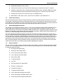
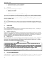
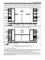
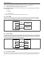
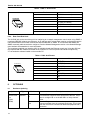
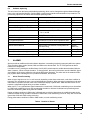
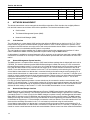
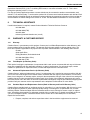
Section 360-381-202
Telecommunications Group
Equipment Issue 2
Fourth Printing, December 2006
T1 Controller with SNMP (3603-81)
CONTENTS
Part 1.
Part 2.
Part 3.
Part 4.
Part 5.
Part 6.
Part 7.
Part 8.
Part 9.
Part 10.
Part 11.
PAGE
GENERAL . . . . . . . . . . . . . . . . . . . . . . . . . . . . . . . . . . . . . . . . . . . . . . . . . . . . . . . . . . . . . . . . . . . . . . . . . . . . . 2
INSPECTION . . . . . . . . . . . . . . . . . . . . . . . . . . . . . . . . . . . . . . . . . . . . . . . . . . . . . . . . . . . . . . . . . . . . . . . . . . . 4
APPLICATION GUIDELINES . . . . . . . . . . . . . . . . . . . . . . . . . . . . . . . . . . . . . . . . . . . . . . . . . . . . . . . . . . . . . 4
TIMESLOT ALLOCATION . . . . . . . . . . . . . . . . . . . . . . . . . . . . . . . . . . . . . . . . . . . . . . . . . . . . . . . . . . . . . . . 7
INSTALLATION . . . . . . . . . . . . . . . . . . . . . . . . . . . . . . . . . . . . . . . . . . . . . . . . . . . . . . . . . . . . . . . . . . . . . . . . . 8
OPTIONING . . . . . . . . . . . . . . . . . . . . . . . . . . . . . . . . . . . . . . . . . . . . . . . . . . . . . . . . . . . . . . . . . . . . . . . . . . . 12
ALARMS . . . . . . . . . . . . . . . . . . . . . . . . . . . . . . . . . . . . . . . . . . . . . . . . . . . . . . . . . . . . . . . . . . . . . . . . . . . . . 13
NETWORK MANAGEMENT . . . . . . . . . . . . . . . . . . . . . . . . . . . . . . . . . . . . . . . . . . . . . . . . . . . . . . . . . . . . . 13
TECHNICAL ASSISTANCE . . . . . . . . . . . . . . . . . . . . . . . . . . . . . . . . . . . . . . . . . . . . . . . . . . . . . . . . . . . . . 14
WARRANTY & CUSTOMER SERVICE . . . . . . . . . . . . . . . . . . . . . . . . . . . . . . . . . . . . . . . . . . . . . . . . . . . 14
SPECIFICATIONS . . . . . . . . . . . . . . . . . . . . . . . . . . . . . . . . . . . . . . . . . . . . . . . . . . . . . . . . . . . . . . . . . . . . . 16
+
PRI
TI
AR AY
MON
TP LP
RCV XMT
ADDRESS
ACO
MGMT
ID
3603−81
PWR
Figure 1. 3603-81 T1 Controller Unit Front Panel
2006 Charles Industries Ltd.
All rights reserved. Printed in United States of America.
The availability of features and technical specifications herein subject to change without notice.
Page 1 of 17
Section 360-381-202
1.
GENERAL
1.1
Document Purpose
This document provides general, installation and testing information for the T1 Controller Unit (T1-S), shown in
Figure 1.
1.2
Equipment Function
The T1-S is part of the 360-80 Intelligent Channel Bank (ICB). It combines the functions of a line interface unit
(LIU) and a channel service unit (CSU), allowing direct connections to public T1 networks.
1.3
Equipment Location/Mounting
Mount the T1-S in the primary slot of the 360-80. In order for the system to operate properly, one controller unit
must be installed in the primary slot.
1.4
1.5
Reference Documentation
360-80 ICB Craft Port User’s Guide (LT360−381−C02)
SNMP Network Node Manager Guide (LT360−381−N02)
Network Management Software Guide (LT360−381−S02)
ICB Troubleshooting User’s Guide (LT360−381−T02)
3608−80 Secondary T1 Unit (LT360−880−202)
Equipment Features
This unit provides the following features:
2
Front panel craft interface
Ethernet Network Management Interface (10/100 Base-T Full/Half Duplex)
Front panel status LEDs
Non-volatile storage of system provisioning and performance
Front panel address switch for network management
Front panel T1 monitor jacks
Dry contacts for alarm indication
Allows internal, loop (recovered from T1) or external (composite clock) timing source
Dual T1, protection or drop and reinsert operation with additional card (3608-80)
Interfaces with HDSL/HDSL2 with adaptor kit
Timeslot assignment on a per-channel basis
Auto framing and identification (SF or ESF)
Auto line coding and identification (AMI or B8ZS)
0 dB digital test tone for equipment level adjustments
Tone test generation and detection on a per-channel basis
Hot unit insertion or extraction
24-channel T1 multiplexing operation
Section 360-381-202
1.6
Temperature hardened (−40 to +65 C)
Combines the functions of a LIU and a CSU, allowing direct connections to public T1 networks
Operates in superframe (SF) or extended superframe (ESF) modes, uses AMI or B8ZS line coding,
and performs loopback, test and performance monitoring of the T1 interface (local and remote)
Complies with UL1950, FCC part 68, FCC part 15 and NEBS Level 1
Meets Bellcore 1089, 43801, 62411, 54016 TR-57 and ANSI T1.403 standards for T1.
Performance History
This unit stores performance history for the last 30 days in 24 hour intervals and over the last 24 hours in 15-minute intervals. This performance history includes failed seconds, errored seconds (ES) and severely errored seconds (SES) (per T1M1.3/93-00). A reset is provided for the current 15-minute interval. A reset is also provided for
the current 24 hour interval and will reset all 15-minute intervals within that 24 hour period.
1.7
Network Management Interface
The ICB stores all configuration settings in the T1-S. This unit is managed through the Network Management Interface (NMI), which controls the provisioning of the unit and obtains status information from the unit. This is
achieved through the craft interface using RS232, SNMP using Ethernet or a proprietary graphical interface using
Ethernet. For operation of this interface, see the Craft Port documentation, SNMP Network Node Manager documentation or Network Management Software documentation.
This unit is shipped with default provisioning for all units in the ICB. The default provisioning for a card may be
found in the documentation that is shipped with the product. Provisioning is altered through the software interface.
If the provisioning is changed, it will maintain the new provisioning even if power is lost. If replaced with a new
unit, the new unit’s provisioning must be changed to the same provisioning as was set for the prior unit. The unit
provides two levels in which provisioning can be reset. “Provisioning Reset to Stored Value” will soft reset the
ICB. “Provisioning Reset to Factory Defaults” will clear all settings for provisioning, timeslots and IP information.
A Real-Time Clock (RTC) is provided through the Network Management interface.
1.8
Status Indicators
This unit is able to provide a variety of status information. The following is a list of all status information available
from the T1-S. Some status information is also provided through front panel LEDs. See individual channel units
for additional status information.
Red (AR) Alarm Status (LED)
Yellow (AY) Alarm Status (LED)
Loss of frame (LOF) Alarm Status
Loss of signal (LOS) Alarm Status
Power status (LED)
T1 framing selected
Line code
Trunk processing (TP) status (LED)
Transmit T1 timing source
Line build out selected
T1 loopback selected (LED)
Loss of valid external timing source (LED)
Carrier Group Alarm Immediate (CGAI) action
Carrier Group Alarm Delayed (CGAD) action
3
Section 360-381-202
1.9
Remote terminal status in a CO/RT configuration
Tone/pattern test generator and error detection
Loopbacks
The T1-S provides three different types of loopbacks.
Near-End Line Loopback
Far-End Line Loopback
Far-End Payload Loopback (available in ESF mode only)
The near-end line loopback transmits information back to the customer or drop side. The two far-end loopbacks
require a remote control link between the near-end and far-end 360-80s. The far-end line loopback transmits both
data and overhead and is used to detect problems with the T1 line. The far-end payload loopback transmits data
only and is typically used to detect problems with T1 processing. The T1-S card also responds to all standard
CSU and T1 loopback codes.
1.10
Testing
The T1-S card provides test tones for analog voice card testing that can be enabled using the network management interface. The T1-S also provides a random pattern generator and loopback code generator for testing data
cards.
2.
INSPECTION
2.1
Inspect for Damages
Inspect the equipment thoroughly upon delivery. If the equipment has been damaged in transit, immediately report the extent of damage to the transportation company.
2.2
Equipment Identification
Charles Industries’ equipment is identified by a model and issue number imprinted on the front panel or located
elsewhere on the equipment. Each time a major engineering design change is made on the equipment, the issue
number is advanced by 1 and imprinted on subsequent units manufactured. Therefore, be sure to include both
the model number and its issue number when making inquiries about the equipment.
2.3
Static Concerns
Each unit is shipped in static-protective packaging to prevent damages from electrostatic charges. Use approved
static-preventive measures, such as static-conductive wrist straps and a static-dissipative mat, when handling
units outside of their protective packaging. A unit intended for future use should be tested as soon as possible
and returned to its original protective packaging for storage.
STATIC-SENSITIVE
This equipment contains static-sensitive electronic devices. To prevent electrostatic charges from
damaging static-sensitive units:
Use approved static-preventive measures (such as static-conductive wrist straps and static-dissipative mats) at all times whenever touching units outside of their original, shipped, protective packaging.
Do not ship or store units near strong electrostatic, electromagnetic, or magnetic fields.
Always use the original static-protective packaging for shipping or storage. Return a tested unit to its
original protective packaging for storage.
3.
APPLICATION GUIDELINES
A typical application of the 360-80 Intelligent Channel Bank (ICB) system using the T1-S is to provide an interface
between the bipolar T1 signal from the public T1 network and data or voice interface units. The T1-S can inter-
4
Section 360-381-202
face to a powered line that uses line-powered repeaters. See Figure 2 and Figure 3 for typical applications. Other
applications use a second T1 interface unit (model number 3608-80) with drop-and-reinsert capability for use in a
fractional T1 span line. For more information on the secondary T1 unit, reference the product documentation.
360−80
CH 1
CH 2
CH 3
.
.
.
CH 7
.
.
.
CH 13
CH 14
CH 15
.
.
.
CH 18
voice
voice
voice
voice
384 KB
384 KB
56 KB
448 KB
time-slot
360−80
T1/DS1
1.544 MB/s
Facility
T1−S
T1−S
1
2
physical
channel
3
4
5
6
13
384 Kb
rate
7
8
9 10
3 1
2
64 Kb ea.
11 12 13 14 15
16 17 18 19
18
448 Kb
CH 1
CH 2
CH 3
.
.
.
CH 7
.
.
.
CH 13
CH 14
CH 15
.
.
.
CH 18
voice
voice
voice
voice
384 KB
384 KB
56 KB
448 KB
20 21 22 23 24
14
384 Kb
15 7
56 Kb 64 Kb
Figure 2. Application #1, Point-Point Full DS1/T1
360−80
360−80
Fractional
T1/DS1
Facility
512 KB/s
CH 3
voice
voice
voice
CH 4
CH 5
.
.
.
CH 3
voice
voice
voice
CH 4
T1−S
T1−S
CH 5
.
.
.
9.6 KB
CH 13
CH 13
9.6 KB
64 KB
CH 14
CH 14
64 KB
56 KB
CH 15
CH 15
56 KB
19.2 KB
CH 16
CH 16
19.2 KB
time-slot
1
physical
channel
3
rate
2
3
4
4
5
64
Kb ea.
14
5
6
7
8
13 16 15
9.6 19.2 56
Kb Kb Kb
9
10 11 12 13 14 15
16 17 18 19
20 21 22 23
24
no traffic data
Figure 3. Application #2, Point-Point Fractional T1/DS1
3.1
Point-to-Point Applications
The 360-80 ICB can be used in point-to-point applications, as shown in Figure 2, and can transport a mix of voice
and data traffic. In these applications, the 360-80 ICB multiplexers are interconnected via a 1.544 MB/s DS1/T1
facility. This facility can be a leased public network channel or a private, dedicated facility.
Figure 2 shows how the 360-80 ICB maps the physical channel unit positions into DS1 facility timeslots. The particular mapping shown is for example only; any physical slot can be mapped into any time-slot. The only restriction to the mapping is that channel units whose bandwidth occupies more than one 64KB time-slot must map their
bandwidth into adjacent timeslots.
5
Section 360-381-202
Figure 3 shows a similar application, except the DS1 facility is fractional “T1”. The 360-80 ICB maps the physical
slots into the first eight timeslots of the DS1 and places “all ones” in the remaining timeslots.
3.2
Additional Applications with Optional Secondary T1 Card
When equipped with a secondary T1 unit (ST1U) in addition to the T1-S, three additional applications/configurations are available. They are:
Dual T1
Protection
Drop and Re-Insert
For additional information, see the documentation on the Secondary T1 unit.
3.2.1.
Dual T1 Mode
The Dual T1 mode allows the T1 of the T1-S and the T1 of the ST1U to be connected to two different 360-80
ICBs. These two T1s run independently of each other and allow the 360-80 system to provide up to 1.5 Mbps to
each T1 for a total of over 3 Mbps of bandwidth. See Figure 4 for a typical configuration.
360-80 (A)
T1-S
ST1U
Primary
T1
Secondary
T1
360-80 (B)
360-80 (C)
Figure 4. Independent Dual T1 Mode
3.2.2.
Protection Mode
The Protection mode allows the T1 of the T1-S and the T1 of the ST1U to be connected to a remote 360-80. The
Primary T1 from the T1-S is used as the transport between the two 360-80s. If the Primary T1 error rate exceeds
a threshold, the system will switch to the T1 from the ST1U (the Secondary T1) as the transport until the Primary
T1 error rate improves. See Figure 5 for a typical configuration.
360-80
T1-S
ST1U
Primary
T1
Protection
T1
360-80
T1-S
ST1U
Figure 5. T1 Protection Application
3.2.3.
Drop and Re-Insert Mode
Drop and Re-insert mode allows the primary T1 from the T1-S to be connected to a channel bank toward the network (west) and the secondary T1 from the ST1U to be connected to a channel bank toward a remote location
6
Section 360-381-202
(east). The data/voice on the Primary T1 can be “dropped” to any one of the cards in the 360-80. Any data/voice
that is not “dropped” to a card in the 360-80 can be reinserted into the T1 on the ST1U and sent to the remote
location. Data/voice from dropped channels is reinserted on the T1 in the same direction it was dropped from. For
example, data/voice dropped from the west would be reinserted toward the west. The same is true from the east.
Additionally, data/voice from cards in the 360-80 can be “re-inserted” into any vacant timeslots to a remote location. This allows better use of the T1 timeslots by keeping them as full as possible between locations. See
Figure 6 for an application in which the 360-80 is used to “drop” dedicated circuits on a T1 and then send the
switched voice to a PBX. See Figure 7 for an application where the 360-80 is used to “drop” channels and re-insert channels from multiple locations to reduce the number of T1s needed between locations by keeping the T1
full. A channel that is dropped and reinserted can terminate on any ICB along it’s path.
T1
360-80 ICB
Full T1 facility @ 1.544
MB/s “800” service
trunks and data
Local PBX
T−1 Trunk
“800” service trunks
Drop and re-insert data channels to data equipment
Figure 6. Drop and Re-Insert Application #1
“West”
Terminal MUX
1
Site 1
A
B
C
360-80 ICB
360-80 ICB
2
“East”
Site 2
360-80 ICB
3
4
23
24
Channels
16
Channels
“Drop & Re-Insert”
8 channels west
16
Channels
“Drop & Re-Insert”
8 channels west
and 8 channels east
“Terminate”
16 channels
24
Figure 7. Drop and Re-Insert Application #2
3.3
HDSL/HDSL2 Applications
Using an adaptor kit (97-001787 DSL Adaptor) the ICB can house a 200-mechanics DSL converter unit. This unit
plugs in to the half-size slot of the ICB and provides an interface between the DSL and the DSL to T1 converter
unit.
The standard DSL adaptor kit provides the interface connections between the incoming DSL and the converter
card, and a T1 output jack and a cable to connect the adaptor and the T1 control unit.
Note:
When using HDSL modules for T1 transport, you may experience some problems with communication
using the T1 facility data link (embedded operations channel) due to the T1 to DSL conversion/synchronization process.
See the documentation for the kit for more information.
4.
TIMESLOT ALLOCATION
4.1
Default Timeslot Allocation
The T1-S uses timeslot allocation to control the routing of data that is sent and received on its T1 interfaces. The
T1 has 24 timeslots, each timeslot can be allocated to any of the channels on any card in the 360-80 system.
7
Section 360-381-202
When a new channel card is installed in the system or a system reset to factory default values is performed, the
default timeslot allocation will be used by the T1-S. When a new card is installed in a system and some of its factory default timeslots have already been allocated to other channels, the timeslot allocation will be different than
the factory default.
For the 360−80 system, the channel number associated with a circuit on a channel card is based on the chassis
slot and the circuit on the card. The table below shows the relationship between the slot, channel numbers and
default timeslots for the channels. It also shows the default number of timeslots per channel (TS/Chan). See individual channel card documentation for more information on timeslot allocation. ‘NA’ indicates ‘Not Allocated’ which
means that these channels have no timeslot allocation during reset to factory default.
Module
3632−80
3633−80
3652−80
3657−85
3658−85
3634−80
3638−80
3641−80
3632−81
3633−81
3652−81
3657−86
3658−86
3634−81
3638−81
4.2
TS/
Chan
1
Slot 1 (lower)
Channel
Default
Numbers Timeslots
1−12
1−12
Slot 2 (upper)
Channel
Default
Numbers Timeslots
13−24
13−24
Half Size Card Slot
Channel
Default
Numbers Timeslots
−−
−−
2
3
12
1
1−6
1−4
1
−−
1−12
1−12
1−12
−−
13−18
13−16
13
−−
13−24
13−24
13−24
−−
−−
−−
−−
25−30
−−
−−
−−
NA
2
3
−−
−−
−−
−−
−−
−−
−−
−−
25−27
25−26
NA
NA
Timeslot Allocation
Timeslot allocation is done through SNMP, NMS or the craft interface. To allocate a timeslot to a channel on a
card in the system, the timeslot must not be allocated to another channel. If the timeslot has already been allocated, the timeslot must be unallocated by selecting the channel (chassis slot) where it is currently allocated and
then deleting it from the timeslot. For example, in Figure 8 timeslot 13 was allocated to channel 16. To allocate it
to channel 20 it must first be unallocated from channel 16, then re-allocated to channel 20.
Any non-allocated timeslots can be allocated to any non-allocated channel. A timeslot cannot be allocated to
more than one channel. Timeslot allocation is done by selecting the channel (chassis slot) associated with the
circuit on the card and then selecting the timeslot to be allocated to that channel. As shown in Figure 8, timeslots
10 to 12 have been allocated to channels 7 to 9.
Some units use multiple timeslots per circuit such as 64xN, ISDN and Router unit. The timeslots allocated for the
circuits on these units must be consecutive. In Figure 8 channel 24 has been allocated to timeslots 22 to 24. Selecting the circuit and then the first timeslot will allocate the correct number of timeslots for the circuit. The system
checks to make sure enough timeslots are available for the circuit, and if there are not enough consecutive timeslots, an error message will be displayed.
The T1-S will transmit an all 1’s signal for any timeslot of the T1 that is not allocated. Any received data in a nonallocated timeslot will not be sent to a channel card.
8
Section 360-381-202
Primary
T1
Timeslot
1
2
3
4
5
6
7
8
9
10 11 12 13 14 15 16 17 18 19 20 21 22 23 24
Channel
1
2
3
4
5
6
7
8
9
10 11 12 13 14 15 16 17 18 19 20 21 22 23 24
Figure 8. Timeslot Allocation w/T1-S Only
4.3
Timeslot Allocation with a T1-S and the Secondary T1 Unit (3608-80)
When the T1-S is used in conjunction with a secondary T1 unit (ST1U), 48 timeslots are available for allocation
(24 for the T1-S and 24 for the ST1U). The timeslot allocation process is similar to that used for the T1-S only.
See the section on timeslot allocation in the Secondary T1 documentation for more information.
5.
INSTALLATION
5.1
Installing the Unit
The T1-S installs in the primary slot of the 360-80. A Secondary T1 unit may be mounted in the secondary slot in
some applications. See Figure 9 for a sample of the shelf layout.
Multichannel Unit
(channels 13−24)
Multichannel/Secondary T1/
HDSL with Adaptor
(channels 25−30)
Multichannel Unit
(channels 1−12)
Primary T1 Controller (T1-S)
Figure 9. 360-80 ICB Common Equipment Configuration
5.1.1.
Attaching the Rear Panel
The rear panel of the unit should be installed before the units are installed in the shelf, and before wiring begins.
+
CCLK
IN
OUT
ALM
AUD
−48V
−48VR
OUT
PRI
T1/E1
NETWORK
MGMT
+
J1
+
VIS
FUSE 4A
IN
CCLK
TERM
J2
+
TERM
3 pin connector— Berg connector
normally between top and middle
pin
4 pin screw terminal connector
4 pin screw terminal connector
Screw terminal block
Figure 10. 3603-81 T1-S Rear Panel with Primary Slot Used ONLY
9
Section 360-381-202
5.1.2.
Installing a New Unit
Use the following steps to install the T1-S.
Action
Step
1.
If not already installed, install the rear panel, screwing it to the appropriate mounting locations on the
shelf using the provided hardware.
WARNING
Due to mechanical differences the T1-S card can only be installed in Issue 3 or greater ICB
shelves. If there is already a rear panel installed on the shelf, check for interference when
installing. The rear panel may need to be removed and replaced with the rear panel that has
been shipped with the new unit.
2.
Insert the unit into the shelf, making sure that the unit is aligned with the card guides inside the shelf.
3.
Slide the unit fully into the shelf. Use the insertion lever to fully seat the unit.
4.
Once the unit is fully inserted, tighten the securing screw on the front panel of the unit.
5.
Wire the unit per the wiring information in the wiring section. When power is applied, the unit will perform a self-test.
6.
After the self-test is performed, check the software provisioning of the card using the front panel craft
interface on the front of the controller unit.
5.1.3.
Installing a Replacement Unit
If you are replacing a unit that is already in service, insure that the new unit is the same as the unit being replaced.
Step
Action
1.
Remove the wiring connectors from the front and rear of the unit (J1 & J2 if applicable).
2.
Unscrew the front panel securing screw to release the unit from the shelf.
3.
Using the card ejector, remove the unit from the shelf.
4.
Follow the procedure for installing a new unit.
5.2
Wiring the Unit
Use the following steps to wire the unit.
Step
Action
1.
Connect T1 to the rear panel RJ48 jack (J1).
2.
If using the Ethernet interface, connect the Ethernet to J2 at the rear of the unit.
3.
Set composite clock termination for your system as described under Hardware Optioning, page 12.
4.
If you are using composite clock, remove the connector and wire the signal to the connector CCLK IN.
5.
Reinstall the connector with the composite clock signal wires.
6.
Power and alarm should already be wired. If not, see the documentation for the ICB shelf.
5.3
Front Panel Switch and LED Definitions
The Audible Alarm Cut Off (ACO) switch is a pushbutton used to open the audible alarm contacts from the
360-80 system. This switch will only mask audible indications of present alarm conditions—it does NOT clear the
alarm. If a new alarm occurs, the audible indication will re-enable.
The Address ID switch on the front panel is a multi-section switch for setting the system address on the system
management bus. This switch is used if the system is connected together with other 360-80 systems into a management control center. This switch allows the control center to ‘address’ the individual systems. See section on
network management for more information.
10
Section 360-381-202
Table 1. LED Definitions
Label
Color
Status
POWER Green ON
AR
AY
Red
The unit is not powered.
ON
The unit is detecting a red alarm on the T1 interface caused by a loss of signal
(LOS) or a loss of framing (LOF) or out of frame (OOF) condition.
OFF
Normal operation.
Yellow ON
Yellow ON
OFF
LP
The unit is receiving power.
OFF
OFF
TP
Indicates that...
Green ON
The unit is receiving a YELLOW alarm condition on the T1. This indicates that a
problem is upstream at some other device or network node.
Normal operation.
The system is processing trunk signaling data based on detected alarm conditions.
Normal operation.
The unit is in a loopback condition. This indication only occurs during testing.
Flashing Valid external timing source has been lost.
OFF
Normal operation.
5.4
Connector Definitions
5.4.1.
Bantam Jacks
The two bantam jacks on the front of the unit allow monitoring of the transmit (XMT) and receive (RCV) sides of
the primary T1 signal without interfering with operation.
5.4.2.
Front Panel RJ11 Jack
The RJ11 jack on the front of the unit is the local craft/control port. The default interface is an RS232 connection
that defaults to 9600 baud, 8 bits, 1 stop and no parity. The interface through the control port is VT-100. VT-100
operation on a PC requires VT-100 emulation software.
A cable (03-200542-0) is available to connect the front panel RJ11 jack to a DB-9 connector.
Table 2. Front Panel RJ11 Jack Pinouts
Pin #
123456
5.4.3.
Use
DB9 Pinouts
1
NC
2
GND
5
3
RCV (ICB − input)
3
4
XMT (ICB + output)
2
5
Enable PC (ICB input)
7
6
NC
T1 Jack
The RJ48 connector on the rear of the T1-S is for the primary T1.
11
Section 360-381-202
Table 3. RJ48 T1 Jack Pinouts
Pin #
12345678
5.4.4.
Use
1
R (RCV from network)
2
T (RCV from network
3
—
4
R1 (XMT to network)
5
T1 (XMT to network)
6
—
7
—
8
—
Rear Panel RJ45 Jack
The J2 RJ45 jack on the rear of the unit is for interfacing to a network management control center using SNMP or
proprietary NMS/GUI software over Ethernet. An IP address and IP subnet mask must be configured through the
craft interface before the unit will communicate with the NMS/GUI or SNMP. To communicate with SNMP, the
SNMP community table must also be configured. See the Network Management section or the Network Management Interface documentation for more information.
The proprietary graphical user interface (GUI) is available through the Ethernet control port. Using the GUI interface requires that GUI software be loaded on the controller PC. The front panel craft interface requires only
VT-100 emulation software loaded on the controller PC.
Table 4. RJ45 Jack Pinouts
Pin #
12345678
6.
OPTIONING
6.1
Hardware Optioning
Option
Type
Composite
3-pin
clock termina- connector
tion
(CCLK
TERM)
12
Use
1
XMT (TD+)
2
XMT (TD−)
3
RCV (RD+)
4
NC
5
NC
6
RCV (RD−)
7
NC
8
NC
Choices
Description
Termination
In
Place the Berg connector between the middle and bottom pins
to terminate the composite clock input wired to the ICB. This is
done for a single ICB, or on the last ICB in a “daisy-chained”
series.
Termination
Out
Place the Berg connector between the top and middle pins to
remove termination from the composite clock input. This is done
when the clock will be connected to additional equipment with a
termination.
Section 360-381-202
6.2
Software Optioning
This unit comes from the factory with default provisioning, which can be changed through the Network Management or the craft terminal interface. See the NMS or craft terminal interface documentation for procedures. The
provisioning options are as follows with the default optioning noted:
Option
Choices
Default
ICB Address (address= 1 + switch setting)
Switch settings 00 through 15
00
T1 Frame format
Superframe (SF), Extended Superframe (ESF)
ESF
Auto detect mode (loop timing only)
No, Yes
No
Transmit T1 Timing Source
External, Internal, Looped
Internal
Line Build Out (LBO)
110, 220, 330, 440, 550, 660 FT or
0, 7.5, 15, 22 dB
0-110 FT
T1 Line Code
AMI, B8ZS
B8ZS
Test Generator (per channel)
Tone Test, 1 KHz 0 dBm0, None
None
T1 Loopback Selection
Line Near End, Line Far End, Payload Far End
None
CGA Process Mode
Normal, CM2, CM3
Normal
Remote Control Method
None, Occupy One Channel, Facility Data Link
(ESF Mode only)
Facility
Data Link
Operation mode
Normal T1, Dual T1, Protection T1
Normal T1
Status (Protection mode only)
Primary T1, Secondary T1
Primary T1
Error threshold (Protection mode only)
0 − 900
250
7.
ALARMS
Alarms provide an audible and visual indication that there is something functioning improperly within the system.
There are three alarm modes, Normal, CM2 and CM3 on the 360-80 shelf. The T1-S will generate an alarm
based on its configuration.
If an alarm occurs, pressing the Audible Alarm Cut-off (ACO) switch stops the audible alert associated with the
alarm. However, it does not clear the alarm. To clear an alarm, the source of the alarm must be identified. Apparent indication of the source will be the unit with the RED alarm displayed. The other units in the network will display a yellow alarm indicating there is a problem somewhere, but not here.
7.1
Alarm Trunk Processing
When a loss of signal occurs for 1 to 2.5 seconds, depending on the alarm mode used, a red alarm condition is
triggered. The unit where the error occurred will display the red alarm. When using the normal alarm mode and a
red condition is present, the other units in the network will display a yellow alarm. CM2 and CM3 modes do not
transmit a yellow alarm signal during a red alarm condition.
When loss of T1 or a yellow alarm signal is detected in normal mode, CGAI trunk conditioning occurs immediately. CGAD trunk conditioning occurs 2.5 seconds after the alarm is declared. Individual card provisioning determines the conditioning state during CGAI and CGAD.
During red alarm conditions in CM2 mode, individual card provisioning determines the conditioning state during
CGAI and CGAD. During red alarm conditions in CM3 mode, trunk conditioning is done to “busy” the circuits and
ignores the CGAI and CGAD card provisioning.
During yellow alarm conditions in CM2 or CM3 modes, no trunk conditioning occurs.
Table 5. Duration of Alarms
Alarm
Normal
CM2
CM3
T1 loss to Red Alarm declared
2.5 Sec.
1 Sec.
1 Sec.
13
Section 360-381-202
T1 restore to Red Alarm retired
15 Sec.
1 Sec.
1 Sec.
Yellow alarm detected to declared
< 1 Sec.
< 1 Sec.
< 1 Sec.
Yellow alarm not detected to retired
< 1 Sec.
< 1 Sec.
< 1 Sec.
Yellow alarm transmitted during alarm
Yes
No
No
8.
NETWORK MANAGEMENT
The 360-80 channel bank can be managed via three different interfaces. Each interface has a slightly different
look and feel however each of them offers similar capabilities. The interfaces available include:
8.1
Craft Interface
The Network Management System (NMS)
Network Node Manager (NNM)
Craft Interface
The craft interface is a menu based ASCII interface that utilizes the RS232 port on the front of the T1-S. This interface utilizes any generic terminal emulation program loaded on a PC or similar equipment to operate. In this
configuration the craft interface can only provision and monitor the 360-80 channel bank it is connected to. Visibility to other remote or local 360-80 channel banks is not provided.
The craft interface is used to establish the IP address required by the other management interfaces. It is also
used to establish the SNMP community parameters required when using the NNM interface.
A cable adaptor is available to connect between the RJ11 connector on the card front panel and a standard DB-9
connection to a terminal or PC serial port. See the documentation provided with the craft interface for more information.
8.2
Network Management System Interface
The NMS interface is a Graphical User Interface (GUI) based software package that is shipped with each unit on
CD-ROM. This interface assumes that the NMS software package is loaded and running on a PC connected to
the same Ethernet network as the T1-S card. Up to 16 local 360-80 channel banks can be provisioned and monitoring with the NMS interface. Each local 360-80 can support up to 7 remote 360-80s connected to each local
360-80. To use this interface the IP address for the local T1-S card must be provisioned using the craft interface.
A local 360-80 channel bank is a 360-80 that is connected directly to the same network as the managing PC. A
remote 360-80 channel bank is a 360-80 that is connected to a local 360-80 over a T1 and the T1 has been provisioned for remote control between the local and remote 360-80s. Remote control can utilize either the Embedded
Operations Channel (EOC), if the T1 is utilizing EFS format, or can utilize a timeslot on the T1. This is done
through the optioning of the T1-S card.
For drop and reinsert applications where a remote 360-80 may be connected to another remote 360-80, each
360-80’s T1-S and Secondary T1 card must be optioned for a remote control method between each 360-80. Each
remote 360-80 is identified through an addressing scheme utilizing the NMS address of the local 360-80 and the
Address ID switch setting on the remote T1-S card. See the NMS documentation for more information.
8.3
Network Node Manager Interface
The NNM interface is a Simple Network Management Protocol (SNMP) based interface that utilizes a central
SNMP manager software package. This interface assumes that an SNMP manager is present on the same Ethernet network as the T1-S card. In order for the SNMP manager to operate correctly, the Management Information
Base (MIB) file included on the CD-ROM that was shipped with the product must be loaded. The NNM interface
allows provisioning and monitoring of as many local 360-80s as can be supported by the Ethernet network. Each
local 360-80 can support up to 7 remote 360-80s connected to each local 360-80. To use this interface the IP address and the community information for the T1-S card must be provisioned using the craft interface.
A local 360-80 channel bank is a 360-80 that is connected directly to the same network as the managing PC. A
remote 360-80 channel bank is a 360-80 that is connected to a local 360-80 over a T1 and the T1 has been provisioned for remote control between the local and remote 360-80s. Remote control can either utilize the Embedded
14
Section 360-381-202
Operations Channel (EOC), if the T1 is utilizing EFS format, or can utilize a timeslot in the T1. This is done
through the optioning of the T1-S card.
For drop and reinsert applications where a remote 360-80 may be connected to another remote 360-80, each
360-80’s T1-S and Secondary T1 card must be optioned for a remote control method between each 360-80. Each
remote 360-80 is identified through an addressing scheme utilizing the community information of the local 360-80
and the Address ID switch setting on the remote T1-S card. See the NNM documentation for more information.
9.
TECHNICAL ASSISTANCE
If technical assistance is required, contact Charles Industries’ Technical Services Center at:
847-806-8500
847-806-8556 (FAX)
800-607-8500
[email protected] (e-mail)
10.
WARRANTY & CUSTOMER SERVICE
10.1
Warranty
Charles offers a 2-year warranty on this product. Contact your local Sales Representative at the address or telephone numbers below for warranty details. The warranty provisions are subject to change without notice. The
terms and conditions applicable to any specific sale of product shall be defined in the resulting sales contract.
Charles
5600 Apollo Drive
Rolling Meadows, Illinois 60008-4049
847-806-6300 (Main Office)
847-806-6231 (FAX)
10.2
Field Repairs (In-Warranty Units)
Field repairs involving the replacement of components within a unit are not recommended and may void the warranty and compatibility with any applicable regulatory or agency requirements. If a unit needs repair, contact
Charles for replacement or repair instructions, or follow the Repair Service Procedure below.
10.3
Advanced Replacement Service (In-Warranty Units)
Charles offers an “advanced replacement” service if a replacement unit is required as soon as possible. With this
service, the unit will be shipped in the fastest manner consistent with the urgency of the situation. In most cases,
there are no charges for in-warranty repairs, except for the transportation charges of the unit and for a testing and
handling charge for units returned with no trouble found. Upon receipt of the advanced replacement unit, return
the out-of-service unit in the carton in which the replacement was shipped, using the pre-addressed shipping label
provided. Call your customer service representative at the telephone number above for more details.
10.4
Standard Repair and Replacement Service (Both In-Warranty and Out-Of-Warranty Units)
Charles offers a standard repair or exchange service for units either in- or out-of-warranty. With this service, units
may be shipped to Charles for either repair and quality testing or exchanged for a replacement unit, as determined by Charles. Follow the Repair Service Procedure below to return units and to secure a repair or replacement. A handling charge applies for equipment returned with no trouble found. To obtain more details of this service and a schedule of prices, contact the Charles Service Center at 217-932-5288 (FAX 217-932-2943).
Repair Service Procedure
1. Prepare, complete, and enclose a purchase order in the box with the equipment to be returned.
15
Section 360-381-202
2. Include the following information:
− Company name and address
− Contact name and phone number
− Inventory of equipment being shipped
− Particulars as to the nature of the failure
− Return shipping address
3. Ship the equipment, purchase order, and above-listed information, transportation prepaid, to the service center address shown below.
Charles Service Center
503 N.E. 15th St
P.O. Box 339
Casey, IL 62420-2054
4. Most repaired or replaced units will be returned within 30 or 45 days, depending on the product type
and availability of repair parts. Repaired units are warranted for either 90 days from the date of repair
or for the remaining unexpired portion of the original warranty, whichever is longer.
11.
SPECIFICATIONS
11.1
Electrical
Parameter
Specification
Carrier Mode
Pulse Code Modulation (PCM) DS1
1.544MB/S Framing Format
T1 interface is compliant with the T1.403 standard:
SF format:
Yellow Alarm
Line loopback, Payload loopback
ESF format:
Yellow Alarm
Facility data link
Line loopback, Payload loopback
Line code (software selectable)
B8ZS or AMI
Transmit Line Build Out (Software selectable)
Short Haul:
(pre-equalization)
(CSU application)
Input/output impedances
100 Ohms
Transmission Rate
1.544 MB/s ± 32 ppm
Jitter Attenuation
12dB @ 11.4 Hz
18 dB @ 22.8 Hz
24 dB @ 45.6 Hz
Channel bank input timing (software selectable)
and composite clock output
1: free running timing
2: loop timing (recovered from receive T1)
3: external timing: composite clock input terminal (on rear
panel).
16
0 − 110 ft.
110 − 220 ft.
220 − 330 ft.
330 − 440 ft.
440 − 550 ft.
550 − 660 ft.
Long Haul (Attenuation): 0dB
(Cable matching)
7.5dB
15dB
22.5dB
Section 360-381-202
Parameter
Specification
T1 connector (rear panel.)
RJ48
PC control interface:
Two types of connectors. (RS232 with RJ11 on
the front and RJ45 Ethernet on the rear of the
ICB)
RJ11 (RS232) craft interface (directly connect PC on front
panel)
Default: data rate 9600, 8 data bit, 1 stop bit, No parity.
RJ45 network management interface (10/100 Base-T,
Full/Half Duplex Ethernet for connection into an Ethernet
network.)
The network management PC interface can control and
monitor functionality for both local and remote environments.
T1 monitor bantam jacks (On front panel only)
This is to monitor the primary T1 signal (monitor transmit
and monitor receive) without interference.
Alarm interface and contacts
The alarm contact connector is a 4-lead connector rated for
1 amp. One set of isolated contacts each for the audible
and visual alarms per PUB-43801. A typical connection is
expected to be 18 or 22 gauge wire.
The system provides visual and audible alarm contact closure when the channel bank is in alarm or there is a loss of
power. When the ACO (Audible Alarm Cut Off) is activated,
the audible alarm contacts return to open circuit.
Composite clock termination (jumper selectable,
rear panel)
IN—135 Ohm termination on composite clock input.
OUT—No termination on composite clock input.
ACO switch (front panel)
Use to silence the audible alarm contacts
Data port test pattern generator and detector
OCU, CSU, DSU, latch loopback code for 64, 56KB/s.
OCU, CSU, DSU non-latching loopback for 56 KB/s and
subrates
V.54 loopback code for 56/64KxN
Voice port test pattern generator and detector
(software selectable on a per-channel basis)
DTMF tone test sequence for channel testing or 1 KHz 0
dBm0 test tone for calibration
Power supply input voltage range
−42V to −56V
Power supply current
0.100 amp
Heat dissipation
4.8 watts
11.2
Physical
See Table 6 for the physical characteristics of the unit.
Table 6. Physical Specifications
Feature
U.S.
Metric
Height
0.75 inch
1.9 centimeters
Width
5.64 inches
13.97 centimeters
Depth
9.25 inches
23.49 centimeters
Weight
10.8 ounces
306 grams
Temperature
−40 to +149 F
−40 to +65 C
Humidity
to < 95%
17