1
System Description
Advant Controller 31
Intelligent Decentralized
Automation System
OPC Series 90
(OLE for Process Control)
Programming
software
907 AC 1131
Visualization 1
Visualization 2
OPC client
OPC client
COM / DCOM
Item list,
derived
from the
symbol file
CoDeSys
OPC server
TCP/IP or Shared Memory
Symbol file
for projects
on PLC 1
and / or
PLC 2
Gateway
Serial, ARCNET, PCI (SL97)
PLC 1
PLC 2
Connections
to several PLCs
are possible
at the same
time
Contents
1
OPC overview
3
1.1
General information about the OPC server
3
1.2
Fields of application for the OPC server
6
1.3
1.3.1
1.3.2
1.3.3
1.3.4
What has to be observed
System requirements
Preparing the AC1131 project
Configuring the OPC server
Planning the client
6
6
7
8
8
2
Installing the CoDeSys OPC server
9
2.1
2.1.1
2.1.2
2.1.3
Required files
Gateway files
OPC server files
Other files
9
9
9
10
2.2
2.2.1
2.2.2
2.2.3
2.2.4
Installation and registration
Installing the gateway and the OPC server
Installation and registration of the OPC server
Registration of the OPC server (update)
Uninstalling the OPC server
10
10
10
10
11
3
Use of the CoDeSys OPC server
12
3.1
General notes
12
3.2
3.2.1
3.2.2
3.2.3
3.2.4
3.2.5
Settings in the programming software 907 AC 1131
Step 1: Creating the data objects
Step 2: Configuring the symbol file
Step 3: Setting the communication parameters in the project
Step 4 (optional): Saving the project
Step 5: Creating the symbol file and transmitting it to the gateway
12
12
13
14
15
15
3.3
3.3.1
3.3.2
3.3.3
3.3.4
3.3.5
Configuring the OPC server using OPCconfig.exe
<File> menu
<Edit> menu
Single-PLC configuration
Multi-PLC configuration
Registry entries (example)
16
18
19
20
25
27
3.4
Starting CoDeSysOPC.exe
28
3.5
Exiting CoDeSysOPC.exe
28
3.6
Starting and exiting Gateway.exe
28
4
Behavior of the OPC server
29
4.1
General recommendations
29
907 AC 1131/Issued: 06/02
1
OPC Server Documentation
12
4.2
Timing behavior of the OPC server
29
5
Connection with an OPC server on another computer
31
5.1
DCOMCNFG.EXE
31
6
Example of an ini file for the OPC server configuration
32
6.1
Example for a multi-PLC configuration
32
7
Brief checklist
34
7.1
Brief checklist
34
8
Index
12
OPC Server Documentation
I
2
907 AC 1131/Issued: 06/02
1
OPC overview
1.1
General information about the OPC server
1
OPC is a standardized interface for the access to process data. It is based on the Microsoft
2
COM/DCOM standard and was extended according to the needs for data access in the
automation technology. Here, it is primarily used to read and write values from the controller.
Typical OPC clients are visualizations or programs for the acquisition of operating data, etc.
OPC servers are normally used for PLC systems and field bus cards.
The OPC server is not a passive subprogram library, but an executable program which is
started when the connection between client and server is established. This is why it is able to
notify the client when the value or status of a variable has changed.
Due to the characteristics of DCOM, even an OPC server can be accessed which is running on
another computer. Furthermore, using OPC a data source can be simultaneously accessed by
more than one client. Another advantage OPC gains by the usage of COM is that different
programming languages (C++, Visual Basic, Delphi, Java) can be used. However, a resulting
disadvantage is the considerably higher usage of resources (memory and CPU time).
Note:
CoDeSys OPC server V2.0 is able to communicate with the controllers mentioned in
section 1.2 Fields of application for the OPC server. It meets the requirements of OPC
standard V2.0.
1
OPC = OLE for Process Control;
OLE = Object Linking and Embedding
See also www.opcfoundation.org and www.opc_europe.org for further information.
2
907 AC 1131/Issued: 06/02
COM = Component Object Model (basis for OLE);
DCOM = Distributed Component Object Model
3
OPC Server Documentation
12
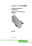
Architecture of the CoDeSys OPC server V2.0
Programming
software
907 AC 1131
Visualization 1
Visualization 2
OPC client
OPC client
COM / DCOM
Item list,
derived
from the
symbol file
CoDeSys
OPC-Server
TCP/IP or Shared Memory
Symbol file
for projects
on PLC 1
and / or
PLC 2
Gateway
Serial, ARCNET, PCI (SL97)
PLC 1
PLC 2
Connection
to several PLCs
are possible
at the same
time
The CoDeSys OPC server uses the CoDeSys gateway server (gateway).
Caution
The basis for the data exchange via the CoDeSys OPC server is the symbol file.
When a project is loaded from the programming system 907 AC 1131 to the controller, it is
possible to simultaneously create a symbol file (*.sym or *.sdb) and store it in the gateway. The
symbol file contains so-called items. An item (data object) exactly corresponds to one variable in
the controller program. Using these items the variable values on the controller can be called.
The OPC server requests the content of the symbol file from the gateway and creates an item
list from it. Because the content of the item list is determined by the variables available in the
controller, it cannot be influenced by the OPC client. The OPC server reads the symbol file last
loaded for a project via the gateway channel.
The item list in the OPC server is updated in definable intervals with the values from the
controller(s). Compared with the direct access to the controller, reading and writing the variable
values via this cache list has the advantage of fast access times (max. approx. 1 ms per item).
A figure drawn from past experience for the amount which can be handled by the OPC without
problems when taking over variables into the item list is approx. 15 000 items, symbol files size
approx. 1.5 MB. The utilization for reading and writing the variable values naturally depends on
the number of items which are set to 'active' and therefore are to be considered when updating
the values. The OPC server supports a categorization of the data to groups. Here it is
distinguished between "public groups" which are allocated by the OPC server and "private
groups" which can be composed by a client.
12
OPC Server Documentation
4
907 AC 1131/Issued: 06/02
If the corresponding option is activated in the configuration, the OPC server groups the items
(i.e. the variables of a project) in a block wise way. Then, one 'public group' is created per block.
'Private groups' can be combined of individual items as desired in the client. First, they do not
affect the grouping in the OPC server but if required they can be made to 'public groups'. For
example, private groups are suitable to activate or deactivate specific variable groups with only
one command depending on whether they are to be accessed or not.
Grouped data should be read by the OPC server in a consistent way, i.e. all variables at the
same time. Please note that this is not always possible for target systems with limited
communication buffers!
Note
It is possible to operate an OPC server which is running on another computer in the
network even if an OPC server is also running on the local computer.
What's new compared to CoDeSys OPC server V1.0:
907 AC 1131/Issued: 06/02
•
The symbol list can be updated without the need to stop a client.
•
Multi-PLC configuration is possible, i.e. simultaneous connection of one client to several
controllers.
•
Exporting and importing OPC configurations is possible (text file *.ini).
5
OPC Server Documentation
12
1.2
Fields of application for the OPC server
The OPC server represents the connection between the client (e.g. the visualization software)
and the controller. The data (items) are read from the controller via the gateway server. The
OPC server makes all read items available for the clients. The client software (visualization)
displays the required items.
The following AC31 controllers can be operated via the OPC server using the corresponding
drivers:
•
•
•
•
•
•
•
•
•
•
07KT95 serial
07KT96 serial
07KT97 serial
07KT97 ARCNET
07KT98 serial
07KT98 ARCNET
07SL97 serial
07SL97 ARCNET
07SL97 PCI
ARCNET routed via 07SL97 PCI
Note
For more detailed information please refer to the 907 AC 1131 documentation / volume
10 / chapter 4 "The individual components" / "Online communication parameters for the
use of gateways" as well as volume 15 / "System technology of the basic units" /
"Programming and testing".
Note
Only the listed controllers and drivers can be used. All controllers with EBS (e.g.
07 KR 91, 07 KT 92-94, series 40/50) cannot be operated with the OPC server.
1.3
What has to be observed
1.3.1 System requirements
When using the OPC server, the used PC plays a major role. Particularly for extensive
configurations (multiple users, many items (variables)) a fast PC should be used in order to
guarantee rapid communication and stable function.
The PC should meet the following minimum requirements:
•
•
•
•
Pentium II
Clock frequency: 500 MHz
128 MB RAM memory
Operating system: WinNT 4.0 Service Pack 5 or higher
Note
The better the system, the faster and more stable the communication with the OPC
server is. Particularly for extensive configurations with multiple users and many items a
fast PC should be used. Fast systems also guarantee that the transmission times listed
in section 4.2 Timing behavior of the OPC server are met.
12
OPC Server Documentation
6
907 AC 1131/Issued: 06/02
1.3.2 Preparing the AC1131 project
First, the OPC variables (items) must be defined in the AC1131 project. For this, either all
variables of the entire project can be defined or the variables of individual program parts (e.g.
programs, defined functions and function blocks) can be enabled.
Note
Particularly for extensive systems the selection of the variables which are to be enabled
is important. The more variables are enabled the higher is the load to the system and
the slower becomes the communication. In order not to load the system with an
unnecessarily high utilization only those variables (items) should be enabled which are
used in the visualization software (client). The corresponding variables must be grouped
during the project planning (e.g. Var_Global: visualization or in individual subgroups,
functions or function blocks).
The definition of the OPC variables is described in section 3.2 Settings in the programming
software 907 AC 1131.
During this process, a file named <projectname>.sym is created which contains all enabled
OPC variables (items). Now this project must be sent via the current gateway to the PLC and
stored there in the Flash memory.
Note
It is important to meet this procedure because the OPC server compares the project
settings in the gateway with the settings in the PLC. If there are any differences, the
items are not displayed or updated in the OPC server.
Caution
Some libraries for earlier versions of 907 AC 1131 have too many symbol entries. Using
these libraries would result in a definition of too many items in the OPC server.
Therefore, only use the libraries listed below for your OPC project:
-
907 AC 1131/Issued: 06/02
ABB-Bib4.lib
ANAI4_20.lib
ARCNET_S90_V41.lib
Base_S90_V41.lib
COM_S90_V42.lib
Coupler_S90_V41.lib
CS31_S90_V41.lib
Datenablage_S90_V41.lib
DeviceNet_Master_S90_V43.lib
IEC_S90_V42.lib
IECSFC_S90_V41.lib
Interbus_Master_S90_V43.lib
PROFIBUS_Master_S90_V43.lib
Profibus_S90_V41.lib
Profibus_S90_V42.lib
PROFIBUS_Slave_S90_V43.lib
RCOM_S90_V41.lib
Systeminfo_S90_V41.lib
7
OPC Server Documentation
12
1.3.3 Configuring the OPC server
In the OPC configuration (OPCConfig.exe) all subscribers are defined from which the items
shall be read. Here, it is important that the program name matches the set gateway driver (e.g.
node address). If this is not the case, no items can be read.
In the OPC configuration also the transmission rate for the items is set. For each subscriber an
individual timeout can be set.
Caution
The following settings must be observed in any case for the AC31 controllers.
Otherwise communication is not possible.
Buffer size = 4800
No login service = enabled
For multi-PLC configurations a mixed usage of a local gateway and TCP/IP is not
possible.
-
Note
For more detailed information refer to section 3.3 Configuring the OPC server using
OPCconfig.exe.
Note
If the project name and the gateway driver do not match, no items are available for the
client.
If the transmission rate and the timeout settings are not correct, the items cannot be
updated. The status BAD is displayed.
1.3.4 Planning the client
For the client, either a client test software (for testing the availability of the items) or a
visualization software supporting OPC can be used.
The OPC server is automatically started when the client software is started and the
communication is established. The corresponding variables are selected from the item list.
When planning the client (visualization software) the communication must be optimized. For
this, the items are divided into individual groups. These groups are defined this way that they
only contain items which have to be updated at the same time. The groups are only activated
when they are needed.
Example:
-
12
Group 1:
Group 2:
Group 3:
Group 4:
...
Group n:
OPC Server Documentation
all failure messages
measurement data (e.g. diagram)
variables fig. 1
variables fig. 2
* always active
* always active
* only active, if fig. 1 is displayed
* only active, if fig. 2 is displayed
variables fig. n
* only active, if fig. n is displayed
8
907 AC 1131/Issued: 06/02
2
Installing the CoDeSys OPC server
2.1
Required files
2.1.1 Gateway files
The gateway files are automatically installed together with the programming software
907 AC 1131. All corresponding files are located in the system directory WINNT\system32:
•
•
•
•
•
•
•
•
•
•
•
•
•
•
•
•
•
Arcnet32.dll
ARCNET DLL for Windows NT4.0
ArcnetN.dll
Commsym.dll
Communication DLL
Commusr.dll
Communication DLL
GArcnet3F4F.dll
ARCNET DLL ARCNET route driver
(is suitable for use with several ARCNET participants)
Gateway.exe
Gateway for communication protocol
GatewayDDE.dll
Gclient.dll
Communication DLL
GDrvABBArcnet.dll
ABB ARCNET driver DLL
(can be used only with one ARCNET participant)
GDrvABBRS232.dll
ABB RS232 driver DLL
GDrvABBRS232Route.dll
ABB RS232(routed) driver DLL
GDrvBase.dll
Communication DLL
GDrvSL97.dll
ABB SL97 PCI driver DLL
GDrvStd.dll
Communication DLL
Ghandle.dll
Communication DLL
Gsymbol.dll
Communication DLL
Gutil.dll
Communication DLL
The OPC server 2.0 requires the gateway from the 907 AC 1131 CD-ROM, version V4.3 or
higher.
After the first start of the gateway the path for the 'Gateway Files' directory is set in the registry
(default: C:\WINNT\Gateway Files). When the connection to the controller is established, the
symbol files created by 907 AC 1131 and stored in the project directory are copied to this
directory. These files are either the symbol files *.sym or their binary version *.sdb. The latter
can be read faster by the OPC server.
2.1.2 OPC server files
The OPC server is installed via the installation menu of the 907 AC 1131 CD-ROM. The files
can be saved to any directory where the DLLs and the file OPCenum.exe must be kept in a
subdirectory named REDIST.
•
•
•
•
•
907 AC 1131/Issued: 06/02
CoDeSysOPC.EXE
DiagnosticOPCClient.exe
OPCCommonSetup.EXE
OPCConfig.exe
OPCConfig_e.exe
OPC server
Client test software
Setup for the files listed below
Configuration of the OPC server
Configuration of the OPC server
9
OPC Server Documentation
12
Subdirectory REDIST (standard OPC 2.0 files):
•
•
•
•
•
•
CALLRPROXY.DLL
OCSDAAuto.DLL
OCSSpy_PS.DLL
OPCCOMN_PS.DLL
OPCenum.EXE
OPCPROXY.DLL
2.1.3 Other files
DCOMCNFG.EXE (C:\WinNT\System32):
This file is used to establish a connection to an OPC server which is installed on another
computer (refer to OPC documentation, chapter 4 Behavior of the OPC server).
2.2
Installation and registration
2.2.1 Installing the gateway and the OPC server
The gateway is automatically installed and registered together with the programming software
907 AC 1131. The OPC server is installed and registered by clicking on the button "Installation
OPC Server" in the installation menu of the 907 AC 1131 CD-ROM. Follow the instructions
given in the setup.
2.2.2 Installation and registration of the OPC server
If you are installing the OPC server afterwards, make sure that the correct gateway server is
used (from 907 AC 1131 CD-ROM, version V4.3 or higher). On the computer, a separate
directory path is created for the program files of the OPC server (e.g.
C:\Programs\AC1131\OPC). All OPC server files (including the subdirectory REDIST) must be
stored to this path.
Using the command
"CoDeSysOPC /Install" (if necessary, the path to the exe file must be entered)
in the 'Run' dialog box, a setup program is started which executes the installation of the OPC
files. Follow the instructions given on the screen. Then the OPC server performs an automatic
registration. A message is displayed, which informs you about the success of the registration
process.
2.2.3 Registration of the OPC server (update)
The possibility of a separate registration is important for program updates or the creation of a
setup. All files of the OPC server update are copied to the present program path.
Using the command
"CoDeSysOPC /RegServer" (if necessary, the path to the exe file must be entered)
only the registration of the OPC server is initiated. The installation of the required files must
have been finished before. If no message is displayed, the registration was carried out
successfully.
(For more information refer to section 3.3.5 Registry entries (example))
12
OPC Server Documentation
10
907 AC 1131/Issued: 06/02
2.2.4 Uninstalling the OPC server
The registration of the OPC server is deleted using the following command:
"CoDeSysOPC /UnRegServer" or "CoDeSysOPC /DeInstall".
This deletes the entries in the registry. However, the installed files are not deleted by this
command!
907 AC 1131/Issued: 06/02
11
OPC Server Documentation
12
3
Use of the CoDeSys OPC server
3.1
General notes
After the OPC server is installed, it should be offered by the OPC client (e.g. visualization) for
selection.
The gateway and the OPC server are automatically started by the operating system as soon as
one of the clients (visualization software) establishes a connection. The OPC server is
automatically exited as soon as all clients have cleared the connection. The gateway stays still
open, but it is inactive.
The steps 3.2.1 to 3.2.3 described below must be carried out to make data objects of a project
in the programming system 907 AC 1131 available for the OPC server and to establish a
connection via OPC.
3.2
Settings in the programming software 907 AC 1131
To enable the OPC server to access the data objects of a project, a symbol file must be created.
For this, start the programming software 907 AC 1131 and open the project.
3.2.1 Step 1: Creating the data objects
The gateway does not use a project file, but a symbol file of the same name with the file name
extension "sym" or "sdb" (binary). This file contains the symbol entries (item list) for the project
variables (refer to OPC documentation, section 2.1.1 Gateway files). To automatically create
this symbol file with each compilation process, the option "Dump symbol entries" must be
selected. The corresponding settings can be made by calling the menu item
<Project><Options>. The automatic creation of the symbol file is set by selecting the category
<Symbol configuration> and then checking the checkbox 'Dump symbol entries'. The dialog
stays open for entering further settings.
12
OPC Server Documentation
12
907 AC 1131/Issued: 06/02
3.2.2 Step 2: Configuring the symbol file
In the 'Set object attributes' dialog, the POUs for which the symbol options shall be set can be
selected in the project structure tree. For this, click on the <Configure symbol file> button in the
presently open dialog or select <Project> <Options> from the menu and then <Symbol
configuration> <Configure symbol file>.
Configuring all POUs (Program Organization Units, User Program Units)
If all project variables shall be defined with the same properties, all POUs must be selected. The
desired attributes are activated by clicking on the checkboxes. When an attribute is active, the
checkbox is filled with a black checkmark. Inactive attributes must be unchecked (white). Grey
checkmarks are not allowed.
Configuring individual POUs
If only variables of individual POUs shall be defined, first all attributes of the entire project must
be deactivated. To do so, select all POUs and deactivate all attribute checkboxes. Now, all
checkboxes must be white.
907 AC 1131/Issued: 06/02
13
OPC Server Documentation
12
Caution
The deletion of object attributes becomes only effective after it is confirmed with the
<OK> button. Each deletion must be confirmed with the <OK> button before further
settings can be made. Otherwise, the object attributes are not deleted.
The dialog 'Set object attributes' must be opened again. Now, the individual project POUs can
be selected and set with the desired attributes.
The following attributes can be set:
Export variables of
object:
The variables of the desired object are written to the symbol file.
Export data entries:
Entries for accessing the total variables are created for structures
and arrays of the object. Assumption: "Export variables of object" is
activated.
Export structure
components:
For the structures of the object one entry is created for each
component of the variable. Assumption: "Export variables of
object" is activated.
Export array entries:
For the arrays of the object one entry is created for each
component of the variable. Assumption: "Export variables of
object" is activated.
Write access:
The OPC server can modify the variables of the object.
3.2.3 Step 3: Setting the communication parameters in the project
The channel of the used gateway is set in the dialog <Online> <Communication Parameters>.
(For more detailed information about the gateway configuration please refer to the 907 AC 1131
documentation / volume 10 / chapter 4 "The individual components" / "Online communication
parameters for the use of gateways" as well as volume 15 / "System technology of the basic
units" / "Programming and testing".) This setting must match the setting configured in the OPC
server (refer to section 3.3 Configuring the OPC server using OPCconfig.exe).
Note
For single PLC configuration:
The OPC server automatically starts with the connection settings last used (these
settings are kept in the registry). These settings can be verified or changed in the file
OPCconfig.exe prior to the start of the OPC server. This means that the setting of the
gateway is automatically updated in the configuration. Each time a project is sent to the
PLC, the corresponding gateway settings are applied.
The gateway connection can be set to local or TCP/IP. A local connection is used, if the OPC
server and the used gateway reside on the same computer. A TCP/IP connection is used, if the
gateway of another computer is accessed by the OPC server via a network.
12
OPC Server Documentation
14
907 AC 1131/Issued: 06/02
Note
A TCP/IP connection can also be used, if the OPC server and the gateway reside on
the same computer. However, with this setting, raised transmission times must be
expected compared to the setting 'local'.
Caution
The following must be observed for multi-PLC configuration:
If the variable values on several controllers shall be accessed via the OPC server, the
corresponding projects must be loaded to these controllers using the same gateway
channel (either local or TCP/IP). A parallel usage of local connection and TCP/IP
connection is not allowed!
Caution
With multi-PLC configuration via ARCNET the following must be considered:
The driver GDrvABBArcnet.dll (ARCNET-Treiber) can only be used for one ARCNET
participant. If several ARCNET participants are employed, the driver GArcnet3f4f.dll
(ARCNET Route) must be used, as it is a multi-PLC driver.
Caution
It is important, that the drivers GDrvABBArcnet.dll (ARCNET) and GArcnet3f4f.dll
(ARCNET Route driver) never can be used at the same time (e.g. GDrvABBArcnet.dll in
the OPC configuration and GArcnet3f4f.dll in the 907AC1131). In this situation, a
system breakdown will occur.
3.2.4 Step 4 (optional): Saving the project
The communication parameters are saved with the project and, after a login, also in the
gateway.
3.2.5 Step 5: Creating the symbol file and transmitting it to the gateway
When compiling the project, the symbol file is created and stored to the project directory. When
downloading the project (<Online> <Login> -> 'Download'), the symbol file (*.sym or *.sdb) with
the present settings is additionally loaded to the gateway (directory 'Gateway Files'). The
communication with the OPC server uses the settings of the symbol file located in the path
\WinNT\Gateway Files\, for example.
The number of symbols should not exceed approx. 15 000 (corresponds to a symbol file
size (*.sym) of approx. 1.5 MB). Please refer to chapter 4 Behavior of the OPC server.
The representation of the variables in the symbol file is the same as in the watch window.
Example:
PLC_PRG.A
PLC_PRG.Struktur.X[4]
.GlobVar1
Caution
Direct addresses cannot be accessed.
907 AC 1131/Issued: 06/02
15
OPC Server Documentation
12
3.3
Configuring the OPC server using OPCconfig.exe
With the configuration it is determined which controllers shall read the symbol entries. For this,
the gateway channel must be determined, the project name must be entered and the individual
parameters (e.g. transmission rate, timeout values, etc.) must be defined. The OPC standard
does not include an interface for the transmission of this information. This is why the project
identifier is written to the registry on each download of a project (refer to section 3.3.5 Registry
entries (example)). The OPC server reads this identifier and searches the symbol file with the
same name.
Caution
Primarily it is important that in the OPC server configuration the project name
corresponds to the used communication driver (i.e. if the communication channel is set
to ARCNET_Node1 and the project name is OPC_Test_program, the ARCNET
subscriber with the Node 1 must have the project OPC_Test_program).
Caution
The following must be observed for a multi-PLC configuration:
If the variable values on several controllers shall be accessed via the OPC server, the
corresponding projects must be loaded to these controllers using the same gateway
channel (either local or TCP/IP). A parallel usage of local connection and TCP/IP
connection is not allowed.
For information about the setting refer to section 3.2.3 Step 3: Setting the communication
parameters in the project or refer to the 907 AC 1131 documentation.
First, it must be determined which mode is used: single PLC or multi PLC. The mode of
operation depends on the following factors:
Mode of operation
Factors
Single PLC
-
This mode is used, if the symbol entries are read by only one
controller.
Note
In the single-PLC mode the configuration of the gateway
channel is adapted automatically, i.e. each time a project is
sent to the PLC, the corresponding gateway settings are
applied to the OPC configuration.
Caution
Single-PLC mode should only be used if it is wanted that the
configuration is automatically adapted.
-
12
OPC Server Documentation
Generally, we recommend to use the setting multi PLC.
16
907 AC 1131/Issued: 06/02
Multi PLC
-
Multi PLC must always be used, if the symbol entries are read by
at least 2 controllers.
-
Multi-PLC mode is also used if the symbol entries are only read
by one controller but the configuration shall not be adapted
automatically, i.e. if the OPC configuration settings shall be
adapted manually. For instance, this is important if you have set
up an ARCNET network with several controllers and the symbol
file shall only be read by one controller (head controller).
Otherwise, if the programming of the other controllers is
performed via the same gateway, the OPC configuration was
changed with each program download.
The following notes should be observed for the use:
Note
A download of the desired project to the corresponding target controller should be
performed immediately before using the OPC server.
Note
When adding or deleting variables in the project, the item list can be updated without
the need to exit the OPC client and OPC server by carrying out a download once again
(with the activated option 'Dump symbol entries'). For instance, the client then receives
a corresponding message (status "bad") when it tries to access a deleted variable.
Note
Please note that a possibly existing boot project does no longer match a project which
was changed and downloaded again. This is why it is recommended to store the
program in the Flash memory of the PLC each time it is downloaded.
For the configuration of the OPC server and the modification of the registry entries of the server,
the configurator OPCconfig.exe is started (refer to OPC documentation 3.3.5 Registry entries
(example)).
The following sections describe the commands of the <File> and <Edit> menus as well as the
specific dialogs for the single-PLC or multi-PLC configuration.
907 AC 1131/Issued: 06/02
17
OPC Server Documentation
12
3.3.1 <File> menu
12
Open
This command opens the configuration last saved using <File>
<Save>.
Save
If the configuration of the server, the PLC(s) and the connection(s) is
finished, it must be saved using this command in order to become
valid.
New
This command opens a new configuration, i.e. the dialogs contain the
default settings or empty input fields.
Single PLC
Using this option, the mode single PLC or multi PLC is selected. If the
menu entry 'Single PLC' is displayed, multi-PLC mode is active. If
the menu entry ' Single PLC' is displayed, single-PLC mode is
active.
Export
Import
Using the <Export> command, the current configuration can be
exported to a text file. For this, the 'Save file as' standard dialog is
opened where you can enter a file name. The default file name
extension ".ini" is appended automatically. The ini file contains the
configuration parameters and can be edited and re-imported using the
command <File> <Import>. When importing a file, the existing ini files
are offered in the 'File open' standard dialog.
OPC Server Documentation
18
907 AC 1131/Issued: 06/02
3.3.2 <Edit> menu
The following commands are available depending on the selection in the configuration tree
('Server', 'PLC' or 'Connection') or depending on the type of configuration (single PLC or multi
PLC).
Append PLC
Multi-PLC mode, settings for the OPC server:
Using this option, another controller is inserted to the configuration,
refer to section 3.3.4 Multi-PLC configuration in the OPC
documentation.
Rename PLC
Multi-PLC mode, settings for the OPC server:
Using this option, a controller previously inserted to the configuration
can be renamed, refer to section 3.3.4 Multi-PLC configuration in the
OPC documentation.
Delete PLC
Multi-PLC mode, settings for the OPC server:
Using this option, a controller previously inserted to the configuration
can be removed, refer to section 3.3.4 Multi-PLC configuration in the
OPC documentation.
Reset PLC
Single PLC and multi-PLC mode, settings for the PLC:
The configuration parameters set with <Edit> <PLC Default Settings>
are loaded from the registry.
PLC Default Settings Always available:
The dialog 'PLC Default Settings' is opened where you can enter your
own values for the PLC configuration settings. This dialog
corresponds to the 'Settings for PLC' dialog (refer to OPC
documentation, section 3.3.3 Single-PLC configuration). The values
set in this dialog are saved to the registry after the dialog is confirmed
with <OK>. Using the command <Edit> <Reset PLC>, these settings
can be re-loaded for a PLC which is selected in the configuration tree.
907 AC 1131/Issued: 06/02
19
OPC Server Documentation
12
3.3.3 Single-PLC configuration
Generally, we recommend to use the setting multi PLC. Proceed as follows to configure an OPC
server for single PLC mode:
Note
Possibly appearing dialogs for saving are not mentioned in the following procedure.
Start the program OPCconfig.exe. First, activate the single-PLC mode by selecting the option
<Single PLC> from the <File> menu. The menu entry is then marked with a checkmark
( Single PLC). Select the menu option <File> <New> to open the following default dialog.
In the left area of the window, the server, the controller (PLC) and the connection are
represented in a tree structure and can be selected by clicking with the mouse. The right part of
the window displays the corresponding configuration dialog for the entry selected in the tree
structure. The <Edit> menu is not used for the single-PLC configuration.
The following server settings can be made in the right part of the window, if the topmost entry
'Server' is selected in the configuration tree.
Update Rate (ms): Default: 200
Basic update rate of the OPC server in milliseconds = Cycle time used for reading all item
values from the controller. These values are written to the cache the client communicates
with using a separately defined update rate.
12
OPC Server Documentation
20
907 AC 1131/Issued: 06/02
Caution
If the update rate is set too low, no communication can be established to the
controller. The status of the items is displayed as BAD in the client. Also refer to
chapter 4 Behavior of the OPC server.
Public Groups: Default: deactivated (no checkmark)
The OPC server establishes one public group for each IEC block as well as for the global
variables.
Sync Init: Default: activated (checkmark)
Synchronous initialization: When starting, the OPC server does not react until the symbol
configuration is loaded.
Log Events: Default: deactivated (no checkmark)
When this option is activated, the actions performed and the errors occurred at the OPC
server are logged and saved to a log file. The file is saved to the project directory and
named OPCServer.log. The messages of several OPC sessions are subsequently listed in
a log file.
The following settings for PLC can be made in the right part of the window, if the entry 'PLC'
under 'Server' is selected in the configuration tree.
907 AC 1131/Issued: 06/02
21
OPC Server Documentation
12
Project name:
Name of the project currently loaded. For single-PLC mode, this entry is not mandatory.
Note
If the communication with the OPC server is performed via the gateway channel
which was used for downloading the program to the PLC, no project name must be
entered. The project name must be entered here, if another gateway channel is
used for the OPC server.
Timeout (ms): Default: 10000
The OPC server exits automatically after this time period if it does not receive an answer
from the controller to a transmitted service.
Number of Tries: Default: 3
Number of attempts the OPC server tries to re-establish the connection to the controller
after a timeout. The time interval between the re-establishment attempts is defined at
'Reconnect Time'.
Buffer Size [Bytes]: Default: 4800
Communication buffer size on the target system. For all AC31 controllers, a buffer size of
< 5000 must be entered.
Wait Time [s]: Default: 10
Time in seconds that the OPC server waits until the controller is ready (important for
controller autostart).
After the OPC server is started, it tries to communicate with the configured controllers. Then
it notifies the client whether communication to the controllers is possible or not. The
controllers must log in within the set wait time, otherwise the status is passed to the client.
Note
The wait time must be set long enough to enable all subscribers to log in. If this time
is set too short it could happen that some subscribers cannot log in during the start.
In this case, the wait time setting should be increased.
This time depends on the number of subscribers and the number of items defined in the
symbol file.
12
OPC Server Documentation
22
907 AC 1131/Issued: 06/02
Note
If the AC1131 project is modified and new items are added to the symbol
configuration, it can happen that the previously set parameters are no longer
correct. In this case the parameters must be adapted (i.e. the wait time must be
increased).
Reconnect Time [s]: Default: 10
Time interval during which the OPC server attempts (as often as set at 'Number of Tries') to
re-establish the connection to the controller via the gateway after a communication breakoff.
Active: Not available (only available in multi-PLC mode)
Motorola Byteorder: Default: deactivated (no checkmark)
The target system of the project does not use the Motorola byte order.
Note
This function is not active for all AC31 controllers.
No Login-Service: Default: activated (checkmark)
This option must be deactivated for specific target systems which require the transmission
of a login service.
Note
The login service may not be transmitted for all ABB controllers. This function must
be activated.
907 AC 1131/Issued: 06/02
23
OPC Server Documentation
12
The following settings for connection to PLC can be made in the right part of the window, if the
entry 'Connection' is selected in the configuration tree.
If no settings are made yet or if the existing settings shall be modified, the Communication
Parameters dialog can be opened by clicking on the button Edit. This dialog is identical to the
gateway settings available in the programming software 907 AC 1131 when selecting <Online>
<Communication Parameters>.
First it is set whether the communication shall use a local or a TCP/IP gateway channel. In
addition, a list of all driver settings is displayed which were loaded via the gateway up to now.
12
OPC Server Documentation
24
907 AC 1131/Issued: 06/02
Here, the driver must be selected with which the OPC server shall communicate. Confirm the
settings with <OK>.
For operating information refer to section 3.2.3 Step 3: Setting the communication parameters in
the project or refer to the 907 AC 1131 documentation.
Now, your selections must have been applied and the dialog box looks as follows:
3.3.4 Multi-PLC configuration
If several controllers shall be configured, the option 'Single PLC' must be deactivated in the
<File> menu.
First, only the entry 'Server' is displayed in the left part of the window. The desired controllers
must be inserted using the command <Edit> <Append PLC>. Then they can be configured
individually as already described for the single PLC configuration.
907 AC 1131/Issued: 06/02
25
OPC Server Documentation
12
Differences compared to the single PLC configuration:
In the Edit menu, the following commands are additionally available for the PLC currently
selected in the configuration tree:
Append PLC
A new 'PLC' entry is inserted. Additional PLCs are always inserted
below the currently highlighted entry. The name "PLC<n>" is
automatically assigned, where n is counted up beginning with 1.
Delete PLC
The highlighted entry is removed from the configuration.
Rename PLC
Each PLC can be assigned a user defined name. To do so, highlight
the desired PLC entry and then select <Edit> <Rename PLC>. An
editing field is opened where you can enter the name.
The name of the project which was downloaded to this controller via the gateway can be
entered to the Project name input field of the 'Settings for PLC' dialog.
Note
If the communication with the OPC server is performed via the gateway channel which
was used for downloading the program to the PLC, it is not required to assign a project
name. The project name must be entered, if another gateway channel is used for the
OPC server.
By selecting or deselecting the option Active in the 'Settings for PLC' dialog it can be defined
whether the controller shall be considered by the OPC server or not.
Caution
It must be observed that the communication is not performed via different gateway
connections. If the variable values on several controllers shall be accessed via the OPC
server, the corresponding projects must be loaded to these controllers using the same
gateway channel (either local or TCP/IP). A parallel usage of local connection and
TCP/IP connection is not allowed.
Caution
With multi-PLC configuration via ARCNET the following must be considered:
The driver GDrvABBArcnet.dll (ARCNET-Treiber) can only be used for one ARCNET
participant. If several ARCNET participants are employed, the driver GArcnet3f4f.dll
(ARCNET Route) must be used, as it is a multi-PLC driver.
Caution
It is important, that the drivers GDrvABBArcnet.dll (ARCNET) and GArcnet3f4f.dll
(ARCNET Route driver) never can be used at the same time (e.g. GDrvABBArcnet.dll in
the OPC configuration and GArcnet3f4f.dll in the 907AC1131). In this situation, a
system breakdown will occur.
12
OPC Server Documentation
26
907 AC 1131/Issued: 06/02
3.3.5 Registry entries (example)
The registry can be displayed using the command "regedit" in the command prompt.
Entries for the 'Settings for OPC server' dialog of the OPC configurator:
[HKEY_CURRENT_USER\Software\3S-Smart
Software
Solutions
GmbH\CoDeSys
OPC\Connections]
* corresponds to the values set in the 'Settings for PLC dialog' of the OPC configurator (refer to
sections 3.3.3 Single-PLC configuration and 3.3.4 Multi-PLC configuration in the OPC
documentation). *
-
"Buffersize"="0x000012c0 (4800)"
"Instances"="00 00 00 00 00 00 00 00
"Motorola0"="No"
"Name0"=""
"NoLogin0"="No"
"Project0"=hex (current communication parameters for the OPC server and project
identification)
"Timeout0"="0x00002710 (1000)"
"Tries0"="0x00000003 (3)"
[HKEY_LOKAL_MACHINE\SOFTWARE\3S-Smart Software Solutions GmbH\CoDeSys
OPC\Config]
* corresponds to the values set in the 'Settings for OPC server' dialog of the OPC configurator
(refer to section 3.3.3 Single-PLC configuration in the OPC documentation). *
-
"LogEvents"="No"
"Multi"="no"
"Public groups"="No"
"Reconnect Interval"="0x00000005 (5)"
"Sync startup"="yes"
"Updaterate"="0x00000064 (100)"
"Wait for target"="0x0000000a (10)"
[HKEY_LOCAL_MACHINE\SOFTWARE\3S-Smart Software Solutions GmbH\CoDeSys
OPC\PLCDefaults]
* corresponds to the values set under <Edit> <PLC Default Settings> in the OPC configurator
(refer to section 3.3.2 <Edit> menu) *
-
907 AC 1131/Issued: 06/02
"Activ"="true"
"Buffersize"="4800"
"Motorola"="false"
"Nologin"="true"
"project"=""
"Reconnecttime"=10"
"Timeout"="10000"
"Tries"="3"
"Waittime"="10"
27
OPC Server Documentation
12
3.4
Starting CoDeSysOPC.exe
The OPC server (and the gateway server) is automatically started by the operating system as
soon as one of the clients establishes a connection. It is not necessary to start it explicitly. If an
OPC server has already been started manually, the client connects automatically to the running
server.
The server is automatically exited again as soon as all clients have cleared the connection.
While the OPC server is running, the icon
the bottom of the screen.
is displayed on the right side of the status bar on
Right-clicking on this icon displays information about the version of the OPC server.
Starting in test mode:
The connection between the OPC server and the client can also be tested if no controller is
linked. For this purpose, the OPC server must be started explicitly using the command
CoDeSysOPC.exe /TestMode
Then it runs in test mode and automatically generates a series of test items which are used to
test the communication to the client.
Caution
The items generated in test mode are only test variables. They are not the variables
from the symbol file of your project.
The OPC icon in the status bar is also displayed while the simulation mode is running.
3.5
Exiting CoDeSysOPC.exe
The OPC server is automatically exited as soon as all clients have cleared the connection.
3.6
Starting and exiting Gateway.exe
The gateway is automatically started by the operating system as soon as one of the subscribers
(e.g. 907 AC 1131, OPC server, OPCConfig or similar) tries to access the gateway server.
on the right side of the status bar on the bottom of the screen indicates that the
The icon
gateway was started and whether it is in use or not.
Once the gateway is started, it stays opened. However, it is indicated whether it is in use or not.
When the gateway is inactive, the icon is shaded in gray
gateway.
. It is not necessary to close the
If required, the gateway can be exited manually. To do so, right-click on the gateway icon to
open the context menu. Select <Exit> to close the gateway server.
12
OPC Server Documentation
28
907 AC 1131/Issued: 06/02
4
Behavior of the OPC server
4.1
General recommendations
The configuration should be optimized as well as possible to enable shortest possible update
times. This is influenced by the following:
4.2
-
Number of subscribers (controllers):
This setting is performed in the OPC configuration. The lower the number of subscribers,
the faster the communication.
-
Number of items:
This setting is performed in the 907 AC 1131 project (creation of symbol file). Only variables
which can be visualized later should be added to the symbol file. The lower the number of
variables, the faster the configuration.
-
Number of active items:
This setting is performed in the client (visualization software). The items should be assigned
to individual groups which are updated at the same time. The groups are only released
when they are needed, i.e. not all items of the project must be updated simultaneously. As a
result, only the currently needed items are read.
-
Correct parameter assignment when setting the OPC configuration:
*The setting of the following parameters is absolutely necessary for AC31 controllers:
- Buffer Size: 4800
- Motorola Byteorder: deactivated
- No Login Service: activated
- The gateway channels for multi PLC mode may not be mixed (do not use local and
TCP/IP in parallel)
* Parameters to be set in order to optimize the communication:
In order to reach a stable communication, the following parameters must be set high
enough.
- Update rate
- Timeout value
- Wait time
- Reconnect time
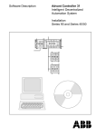
Timing behavior of the OPC server
For serial connection it is recommended to use the single-PLC mode.
For ARCNET connections generally the multi PLC mode could be used (this depends on the
function of the automatic configuration adaptation, refer to section 3.3 Configuring the OPC
server using OPCconfig.exe). The more subscribers and items are configured, the slower is the
communication.
Caution
If the transmission rate is set too low in the configuration, the communication becomes
considerably slower or is no longer performed. The transmission rate should be set
approximately to the value which can be reached.
907 AC 1131/Issued: 06/02
29
OPC Server Documentation
12
Note
For configurations with several subscribers, the transmission rates between the
individual subscribers can differ. The value set in the configuration must be adjusted to
the subscriber with the slowest communication.
Serial
ARCNET
Single PLC
1 subscriber
4 items
100 items
500 items
800 items
Multi PLC
Single PLC
Multi PLC
Update
rate
[ms]
Measured
time
approx.
[s]
Update
rate
[ms]
Measured
time
approx.
[s]
Update
rate
[ms]
Measured
time
approx.
[s]
Update
rate
[ms]
Measured
time
approx.
[s]
50
500
1000
1000
0.1
1
3
7
50
500
1000
1000
0.2
1
3
7
50
100
500
500
0.05
0.5
2
3
50
100
500
500
0.05
0.5
2
3
-
-
-
-
-
-
100
100
500
2000
0.2
0.5
2
7
-
-
-
-
-
-
1000
1000
1000
3000
1
2-4
4-7
7-12
6 subscribers
24 items
100 items
1000 items
4800 items
9 subscribers
36 items
100 items
1000 items
7200 items
12
OPC Server Documentation
30
907 AC 1131/Issued: 06/02
5
Connection with an OPC server on another computer
5.1
DCOMCNFG.EXE
Using DCOMCNFG.EXE from the system directory, a connection to an OPC server on another
computer can be established. For this purpose, select the entry 'OPC server for CoDeSys...' in
the 'Applications' tab and then click on the 'Properties' button. In the properties dialog, open the
'Location' tab, activate the option 'Run application on the following computer' and then enter the
desired computer.
For such a connection it is assumed that an OPC server is also running on the local computer.
907 AC 1131/Issued: 06/02
31
OPC Server Documentation
12
6
Example of an ini file for the OPC server configuration
6.1
Example for a multi-PLC configuration
The ini file of the OPC server configuration can be exported from OPCConfig.exe to a text file
and then edited and re-imported again to OPCConfig.
The following is an example of ini file entries (multi-PLC mode with 2 subscribers):
12
Entry
[Server]
updaterate=200
publicgroups=0
logevents=1
syncinit=1
PLCs=2
PLC0=PLC1
PLC1=PLC2
Meaning
Settings for the OPC server
Transmission rate [200ms]
Public Groups [deactivated]
Create log file [activated]
Sync Init [activated]
Number of subscribers [2]
PLC name subscriber 1 [PLC1]
PLC name subscriber 2 [PLC2]
[PLC:PLC1]
active=1
motorola=0
nologin=1
timeout=10000
tries=3
waittime=10
reconnecttime=10
buffersize=4800
project=PLC1.pro
gateway=Local
device=ABB Arcnet Route
instance=ARC_3F_1
parameters=10
parameter0=Sender node
value0=254
parameter1=Target node
value1=1
parameter2=Receive Timeout
value2=2000
parameter3=Routing levels
value3=0
parameter4=Coupler (Level 1)
value4=0
parameter5=Channel (Level 1)
value5=0
parameter6=Address (Level 1)
value6=0, 0, 0, 0, 0
Settings for PLC1
Subscriber active [activated]
Motorola byte order [deactivated]
No login service [deactivated]
Timeout value [10s]
Number of reconnect attempts [3]
Wait time [10s]
Reconnect time [10s]
Buffer size [4800]
Project name [PLC1.pro]
Gateway channel [local]
Parameters for the gateway
connection to PCL1 (driver
setting):
- gateway driver [ABB ARCNET
Route]
- driver name [ARC_3F_1]
- node number 1
OPC Server Documentation
32
907 AC 1131/Issued: 06/02
907 AC 1131/Issued: 06/02
Entry
parameter7=Coupler (Level 2)
value7=0
parameter8=Channel (Level 2)
value8=0
parameter9=Address (Level 2)
value9=0, 0, 0, 0, 0
Meaning
[PLC:PLC2]
active=1
motorola=0
nologin=1
timeout=10000
tries=3
waittime=10
reconnecttime=10
buffersize=4800
project=PLC2.pro
gateway=Local
device=ABB Arcnet Route
instance=ARC_3F_2
parameters=10
parameter0=Sender node
value0=254
parameter1=Target node
value1=2
parameter2=Receive Timeout
value2=2000
parameter3=Routing levels
value3=0
parameter4=Coupler (Level 1)
value4=0
parameter5=Channel (Level 1)
value5=0
parameter6=Address (Level 1)
value6=0, 0, 0, 0, 0
parameter7=Coupler (Level 2)
value7=0
parameter8=Channel (Level 2)
value8=0
parameter9=Address (Level 2)
value9=0, 0, 0, 0, 0
Settings for PLC2
Subscriber active [activated]
Motorola byte order [deactivated]
No login service [deactivated]
Timeout value [10s]
Number of reconnect attempts [3]
Wait time [10s]
Reconnect time [10s]
Buffer size [4800]
Project name [PLC2.pro]
Gateway channel [local]
Parameters for the gateway
connection to PLC1 (driver
setting):
- gateway driver [ABB ARCNET
Route]
- driver name [ARC_3F_2]
- node number 2
33
OPC Server Documentation
12
7
Brief checklist
7.1
Brief checklist
Please check the following if the communication via OPC does not work:
1. Gateway installed and running? Icon in the taskbar (right side on the bottom) active?
2. Installation and registration of the OPC server ok?
Is automatically performed when "CoDeSysOPC /Install" (installation + registration) or
"CoDeSysOPC /RegServer" (registration only) are executed.
3. Project preparation / settings in the AC1131 programming system ok?
<Project> <Options>: 'Dump symbol entries' selected?
Communication parameters: Selected gateway channel ok?
Project saved, compiled and download performed?
The symbol files *.sym and *.sdb must exist in the path WinNT\Gateway Files.
4. If OPC shall be used on another computer (only possible if the OPC server is also running
on the local computer and if the AC1131 project is not additionally accessed (currently
logged in) on the other computer):
Establish a connection to the other computer using DCOMCNFG.EXE (in the system
directory):
- select the entry 'OPC server for CoDeSys...' in the 'Applications' tab,
- click on the 'Properties' button, open the 'Location' tab, activate 'Run application on the
following computer' and then enter the desired computer.
5. Verify the connection and the server settings: OPCCFG.EXE:
- Connection: (entry must correspond to the valid gateway channel set in the AC1131
communication parameters)
- Usual server settings: Update Rate 200ms, Public Groups: No, Sync Init: No
Usual PLC settings: Communication Timeout 10 s (10000)
Number of (Reconnect) Tries: 3, Buffer Size: 4800, Wait Time (target system): 10s
Reconnect Time: 10s, Active: yes, Motorola Byteorder: no, No Login Service: yes
Connection settings for PLC: Caution: For multi PLC mode, local and TCP/IP cannot be
mixed, verify driver settings
- Save -> The new configuration becomes effective when a new connection to the OPC
server is established.
6. Verify whether symbol entries are available: DiagnosticOPCClient.exe
Establish connection (Connect OPC-Server) -> in the right-hand window, right-click on
Private Groups, confirm the dialog with OK, right-click on the created group entry -> add all
items -> all created symbol entries (variables) should be displayed now.
The OPC server is automatically exited as soon as all clients have cleared the connection to it.
The OPC server is displayed in the Task Manager as a process.
12
OPC Server Documentation
34
907 AC 1131/Issued: 06/02
8
Index
PC 6
project name 22, 26
A
active 23
R
reconnect time 23
registry 27
B
buffer size 22
S
C
single PLC 14, 16, 18, 20
symbol file 4, 7, 12, 13, 15
synchronous initialization 21
system requirements 6
client 3
communication parameters 14
configuration 16, 29
controllers 6
T
D
TCP/IP 14
timeout 22
drivers 6
U
G
update rate 20
gateway 9, 10, 14, 15, 26, 28
W
I
wait time 22
item 4
items 7, 12, 13
L
libraries 7
local 14
log events 21
login service 23
M
Motorola Byteorder 23
multi PLC 15, 16, 17, 18, 25
N
no login service 23
number of tries 22
O
OPC 3
OPC server 3, 6, 9, 10, 28, 29
P
parameters 8
907 AC 1131/Issued: 06/02
I
OPC Server Documentation
12
Manual No.: 2CDC 120 070 M 0202
ABB STOTZ-KONTAKT
Eppelheimer Straße 82
69123 Heidelberg
Germany
Telephone
Telefax
E-Mail
Internet
GmbH
Postfach 101680
69006 Heidelberg
Germany
+49 6221 701-0
+49 6221 701-1111
[email protected]
http://www.abb.de/stotz-kontakt