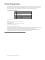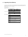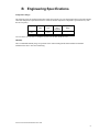
1
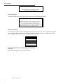
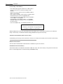
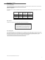
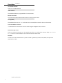
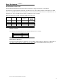
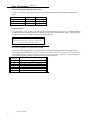
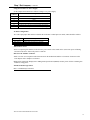
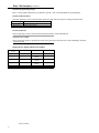
American Megatrends, Inc. Titan-II PCI Pentium EISA Motherboard User's Guide MAN-711 1/6/95 © Copyright 1994 American Megatrends, Inc. All rights reserved. American Megatrends, Inc. 6145F Northbelt Parkway Norcross, GA 30071 This publication contains proprietary information which is protected by copyright. No part of this publication may be reproduced, transcribed, stored in a retrieval system, translated into any language or computer language, or transmitted in any form whatsoever without the prior written consent of the publisher, American Megatrends, Inc. Limited Warranty Buyer agrees if this product proves to be defective, that American Megatrends, Inc. is only obligated to replace or refund the purchase price of this product at American Megatrends' discretion according to the terms and conditions on the motherboard warranty card. American Megatrends shall not be liable in tort or contract for any loss or damage, direct, incidental or consequential. Please see the Warranty Registration Card shipped with this product for full warranty details. Limitations of Liability In no event shall American Megatrends be held liable for any loss, expenses, or damages of any kind whatsoever, whether direct, indirect, incidental, or consequential, arising from the design or use of this product or the support materials provided with the product. Trademarks Intel is a registered trademark of Intel Corporation. MS-DOS, Xenix, and Microsoft are registered trademarks of Microsoft Corporation. IBM, AT, VGA, PS/2, OS/2, and EGA are registered trademarks of International Business Machines Corporation. XT and CGA are trademarks of International Business Machines Corporation. Fujitsu is a registered trademark of Fujitsu America, Inc. Motorola is a registered trademark of Motorola Corporation. Hitachi is a registered trademark of Hitachi America, Ltd. PNY is a registered trademark of PNY Corporation. Oki is a registered trademark of Oki America, Inc. NEC is a registered trademark of NEC Corporation. Samsung is a registered trademark of Samsung Electronics Corporation. Siemens is a trademark of Siemens Corporation. Mitsubishi is a registered trademark of Mitsubishi Electronics of America. Micron is a registered trademark of Micron Corporation. Unix is a registered trademark of American Telephone and Telegraph Company Bell Laboratories. Weitek is a trademark of Weitek, Inc. Toshiba is a registered trademark of Kabushiki Kaisha Toshiba. Revision History 1/6/95 Initial release. Table of Contents 1 System Overview ............................................................................................. 1 2 Installation ....................................................................................................... 9 Unpacking the Motherboard ............................................................ 9 Installation Steps ............................................................................ 11 Step 1 Set Switch and Jumper Options ......................... 11 Step 2 Install Memory................................................... 15 Step 3 Install CPU ........................................................ 16 Step 4 Install the Motherboard ...................................... 17 Step 5 Connect the Power Supply ................................. 18 Step 6 Connect the Keyboard Cable ............................. 20 Step 7 Connect Cables .................................................. 21 Step 8 Connect the Mouse Cable .................................. 22 Step 9 Connect Onboard I/O ......................................... 23 Step 10 Install Floppy Drive ......................................... 24 Step 11 Install Hard Disk .............................................. 25 Step 12 Install Adapter Cards ....................................... 26 Step 13 Test and Configure .......................................... 27 3 AMIBIOS and WINBIOS .............................................................................. Advanced Setup.............................................................................. Chipset Setup ................................................................................. Power Management Setup .............................................................. Peripheral Setup ............................................................................. 4 Flash Programming ....................................................................................... 43 A Upgrading Cache Memory ............................................................................ 45 29 31 37 38 39 Index ................................................................................................................................. 47 Titan-II PCI Pentium EISA Motherboard User's Guide iii Preface Technical Support If an American Megatrends motherboard fails to operate as described or you are in doubt about a configuration option, please call technical support at 404-246-8645. American Megatrends BBS The BBS permits OEMs, VARs, and system integrators to access technical information about motherboard and BIOS products. Product Engineering Change Notices, Tech Tips, Technical Notes, and complete technical manuals are available on the BBS. Data Transmission Rates The BBS automatically handles modems with data transmission rates from 1,200 to 28,800 bps. BBS Phone Numbers The following table lists the characteristics of the BBS phone numbers. The BBS requires no parity, 8 data bits, and 1 stop bit. Phone Number Characteristics 404-246-8780 US Robotics 28,800 bps. Supports every v.xx communications standard. US Robotics 28,800 bps. Supports every v.xx communications standard. US Robotics dual standard. Can handle 2,400, 9,600, or 14,400 bps. Supports HST or v.32. US Robotics 14,400 bps v.32. Supports high speed v.32. 404-246-8781 404-246-8782 404-246-8783 Acknowledgments This manual was written by Sudhakaran Valappil and Julia McDonald. Preface iv 1 System Overview The American Megatrends Titan-II motherboard has: • Single or Dual Intel® P54C Pentium 3.3 Volt CPU operating at 90, 120, or 150 MHz internally, • six EISA expansion slots, and • four PCI expansion slots. The motherboard conforms to the PCI Version 2.0 specification and uses the PCI local bus. The PCI slots operate synchronously with the CPU clock. The following table illustrates the frequency assignments: CPU External Clock Frequency PCI Expansion Slots Frequency 66 MHz 60 MHz 50 MHz 33 MHz 30 MHz 25 MHz The frequency will vary according to the version of the motherboard ordered. The PCI expansion slots are automatically configured by the onboard American Megatrends WINBIOS system BIOS. Motherboard Dimensions The Titan-II PCI Pentium EISA motherboard is approximately 12.1 inches wide by 13.8 inches long (the standard full AT® motherboard size with similar mounting hole locations). Processor Type and Speed The motherboard uses a 3.3V 90, 120, or 150 MHz (internal speed) Intel P54C or P54CT Pentium CPU operating externally at 50, 60, or 66 MHz in the single processor mode. There are two CPU sockets on the motherboard to support dual processors. Refer to page 18 for instructions on upgrading to dual processors. Titan-II PCI Pentium EISA Motherboard User's Guide 1 Description Note The motherboard is not field upgradeable from one speed to another. Heat Sink with Fan A heat sink with fan must be used with all Intel Pentium CPUs on all Pentium motherboards. Caution Adequate air flow in the chassis must be provided when using dual processors. Installation of an 8 cm 0.2 amp fan at the front of the chassis is recommended to pull air in. This is in addition to the fan at the back of the case which pulls air out. Main System Memory The motherboard requires Fast Page Mode SIMMs operating at 70 ns (RAS access time). The motherboard supports up to 256 MB of onboard system memory via four 64-bit banks with the following types of SIMMs (Single Inline Memory Modules). Either two, four, six or eight SIMMs must be mounted. SIMM Type 256 KB x 36 SIMMs 512 KB x 36 SIMMs 1 MB x 36 SIMMs 2 MB x 36 SIMMs 4 MB x 36 SIMMs 8 MB x 36 SIMMs 16 MB x 36 SIMMs Fast ATA This motherboard supports the Fast ATA specification. Chapter 1 System Overview 2 Description, Continued L2 Secondary Cache Memory • The motherboard supports 256 KB or 512 KB of direct mapped, write-back L2 external (secondary) cache memory. • Thirty-two (32) pin sockets exist for 256 KB/512 KB of DIP L2 cache memory. • The external (secondary) cache memory is mounted on the motherboard in two rows of four SRAMs each. • For 256 KB cache with a 60/90 MHz CPU, the SRAM is 15 ns 32 KB x 8 3.3V SRAMs. • For upgrading to 512 KB the 32 KB x 8 3.3V SRAMs should be replaced by 64 KB x 8 15 ns 3.3V SRAMs in the same sockets. • For a 66/100 MHz CPU, 12 ns SRAMs should be used. Caution You must use 3.3V SRAMs when upgrading from 256 KB to 512 KB of L2 cache memory. Shadowed ROM areas such as the system BIOS and Video BIOS can be cached and write-protected via Advanced Setup. Cache memory is enabled and disabled through WINBIOS Setup Advanced Setup. Amount of System Memory That Can be Cached All installed system memory can be read from or written to L1 internal cache memory and L2 external cache memory. Hardware Reset Switch The Titan-II PCI Pentium EISA motherboard has a standard two-pin reset connector. Pentium Internal Cache Memory The Intel Pentium has an 8 KB data cache and an 8 KB code cache. This cache memory can be placed in either writeback or write-through mode via Advanced Setup in WINBIOS Setup. Titan-II PCI Pentium EISA Motherboard User's Guide 3 Description, Continued Shadow RAM The system BIOS ROM is always shadowed. Video BIOS and Adaptor ROM shadowing can be enabled via Advanced Setup in 16 KB increments. System BIOS The Titan-II PCI Pentium EISA motherboard has a 128 KB WINBIOS with built-in WINBIOS Setup and userdefinable hard disk drive types. The BIOS is stored in Flash EPROMs and can be reprogrammed via software without removing the ROM. CMOS RAM The Titan-II PCI Pentium EISA motherboard has 114 bytes of CMOS RAM on the Real Time Clock. The contents of CMOS RAM are configured by AMIBIOS Setup, resident with the system BIOS on the Flash EPROM. There is also an additional 8 KB of EISA Extended CMOS RAM. Real Time Clock The motherboard has a real time clock and CMOS RAM with built-in battery backup for WINBIOS Setup. Onboard I/O • two 40-pin IDE connectors for up to four IDE drives, with PCI local bus IDE Mode 3 support, • a 34-pin connector to a floppy controller that supports up to two 720 KB, 1.2 MB, 1.44 MB, or 2.88 MB floppy drives with vertical recording support for 2.88 MB floppies, • two ten-pin connectors for serial ports, • a 26-pin connector for one bidirectional parallel port (with ECP and EPP support) on the motherboard, and • a 10-pin berg for a PS/2 mouse connector. Chapter 1 System Overview 4 Description, Continued Up to Four IDE Drives The motherboard supports up to four IDE drives through two 40-pin IDE connectors, marked Primary and Secondary. IDE Drive Assignments If four IDE drives are connected, WINBIOS assigns the physical drive numbers; DOS assigns the logical drive letters as follows: IDE Drive Drive Number Drive Letter if One Partition on Drive Drive Letter if Two Partitions on Drive Primary Master Primary Slave Secondary Master Secondary Slave 80h 81h 82h C:\ D:\ E:\ G:\ H:\ I:\ 83h F:\ J:\ IDE Autodetect All IDE drives assigned to the secondary IDE connector are autodetected. Caution If the parameters for an IDE drive cannot be automatically detected by WINBIOS correctly, or if you are using a CHS (Cylinder-Head-Sector) translation mechanism that is different than the native mode of the IDE drive, the drive should not be attached to the secondary IDE controller. Power Management The motherboard supports power management services, including: Green PC LED, signals to control Green PC-aware power supplies, automatic power down of IDE drives and video monitor and monitor blanking (HSYNC, VSYNC, and SYNCEN). The EPA Green PC specification is supported through the Megakey keyboard controller. The SMI (System Management Interrupt), APM, and system stop clock are supported. Titan-II PCI Pentium EISA Motherboard User's Guide 5 Description, Continued Seven DMA Channels There are seven DMA channels. Timer Features The motherboard has three programmable 16-bit counter/timers. Refresh Generation The Titan-II PCI Pentium EISA motherboard has a refresh generation feature. I/O Capability The motherboard accesses 32-, 16- or 8-bit I/O devices on the EISA bus and 32-bit devices on the PCI bus. Green PC Monitor Connector A 10-Pin dual-in-line connector for Green PC monitor support through the feature connector. Fifteen Interrupt Levels There are 15 hardware interrupt levels. The NMI takes precedence over all hardware interrupts. IRQs 3, 4, 5, 7, 9, 10, 11, 12, 14, and 15 can be allocated for use on either the ISA bus or the PCI bus. EISA Bus The EISA bus in the motherboard has a system clock that is generated by the bus clock (BCLK) and operates at approximately 8 MHz. Chapter 1 System Overview 6 Description, Continued EISA and PCI Expansion Slots The Titan-II PCI Pentium EISA motherboard has the following EISA and PCI expansion slots: • four PCI expansion slots, and • six EISA expansion slots for EISA/ISA adapter cards. All PCI expansion slots are bus mastering. All 6 EISA slots are bus mastering. The PCI expansion slots are automatically configured by the onboard American Megatrends WINBIOS system BIOS. PS/2 Mouse A 10-pin berg header that can be attached via a customized serial cable to a PS/2-type mouse. Contact American Megatrends for cable and adapter information. Speaker A standard four-pin speaker connector. I/O Address Space I/O addresses 0100h through 03FFh are available on the ISA bus. If enabled, onboard peripheral devices use the standard AT I/O port address ranges. Keyboard The motherboard uses a five-pin circular DIN connector and has a five-pin keyboard lock connector to prevent unauthorized access. Titan-II PCI Pentium EISA Motherboard User's Guide 7 Chapter 1 System Overview 8 2 Installation Unpacking the Motherboard Step 1 2 3 4 5 6 7 Action Inspect the cardboard carton for obvious damage. If damaged, call American Megatrends Technical Support at 404-246-8645. Leave the motherboard in its original packing. Perform all unpacking and installation procedures on a ground connected anti-static mat. Wear an anti-static wristband, grounded at the same point as the anti-static mat or use a sheet of conductive aluminum foil grounded through a 1 megohm resistor instead of the anti-static mat. A strip of conductive aluminum foil wrapped around the wrist and grounded through a 1 megohm resistor serves the same purpose as the wristband. Inside the carton, the motherboard is packed in an anti-static bag, sandwiched between sheets of sponge. Remove the sponge and remove the anti-static bag. Place the motherboard on a grounded anti-static surface component side up. Save the original packing material in case of reshipment. Inspect the motherboard for damage. Press down on all ICs mounted in sockets to verify proper seating. Do not apply power to the motherboard if it has been damaged. If the motherboard is undamaged, it is ready to be installed. Titan-II PCI Pentium EISA Motherboard User's Guide 9 Chapter 2 Installation 10 Step 1 Warning This motherboard contains sensitive electronic components which can be easily damaged by static electricity. Follow the instructions carefully to ensure correct installation and to avoid static damage. Set all user-configurable jumpers and switches, and then install upgrade processors before installing the motherboard in the chassis. The jumpers are: Jumpers J27 J23 J28, J29 J9 J18 J16 and J17 J1, J2, J3, J11, J19 J7 J5 P24 J20 J24 J22 J21 J23 J6 J10 Description Set IRQ12 Clear password Set bus frequency Cache Memory Configuration Parallel Port IRQ Select Extended Parallel Port DMA Select 3.3V Power Supply Configuration CPU Internal Clock and External Clock Ratio P54C/CM CPU Type Select Green PC Monitor Connector Green PC Power Switch Connector Flash BIOS Programming Voltage Password LED Select Password LED Power Save Switch APIC (Advanced Programmable Interrupt Controller) Configuration PLL Test Mode J9 Cache Memory Configuration J9 is a three-pin berg that controls the L2 secondary cache memory configuration on the motherboard. Cache Memory 256 KB 512 KB J9 Short Pins 1-2 Short Pins 2-3 Titan-II PCI Pentium EISA Motherboard User's Guide 11 Step 1 Set Jumpers, Continued J27 IRQ12 J27 is a two-pin berg that selects IRQ12 for use by the onboard PS/2 mouse. When an onboard PS/2 mouse is used in the computer, J27 should be shorted. Leave J27 OPEN is no PS/2 mouse is used. J27 Setting IRQ12 Select Shorted OPEN PS/2 mouse is present. PS/2 mouse is absent. J23 Clear Password The J8 DIAG switch is not used to clear CMOS RAM in Rev C Titan II motherboards. On Rev.B and B1 Titan II motherboards, J8 was used to clear CMOS RAM. On Rev C motherboards, use the J23 Sleep switch to erase CMOS RAM, which erases the password. To erase a password: Step 1 2 Action Turn the computer power off and install a shorting bridge on J23 (Sleep Switch). Turn the computer power on again. Wait until CMOS Checksum Bad. 3 4 5 appears. Turn power off. Remove the shorting bridge from J23 (leave J23 OPEN again). Turn power on again. Run WINBIOS Setup and choose the proper system configuration settings. Boot the computer. Chapter 2 Installation 12 Step 1 Set Jumpers, Continued J28 and J29 Bus Frequency Select The Titan-II EISA motherboard supports Intel CPUs that operate at voltage levels between 3.135 and 3.6V. J28 and J29 are two-pin jumpers that support the 150 MHz P54C CPU. These jumpers should be shorted when a 150 MHz P54C CPU is installed. Short J29 when a 150 MHz P54C CPU is installed in U35. Short J28 when a 150 MHz P54C CPU is installed in U34. Also, J7 should be shorted when a 150 MHz P54C CPU is installed. When using dual processor mode, both CPUs should be the same speed. J28 J29 J7 Bus to Core Frequency CPU Speed (External/ Internal) Open Open Closed Closed Open Open Closed Closed Open Closed Open Closed 2:3 1:2 1:3 2:5 60/90 MHz 60/120 MHz 60/180 MHz 60/150 MHz J10 PLL Test Mode J10 is a three-pin berg that enables the PLL test mode during In-Circuit Testing. PLL Test Mode PLL Test Mode Normal Operating Mode J10 Short Pins 1-2 Short Pins 2-3 J18 Parallel Port IRQ Select J18 is a three-pin single-inline berg. Short pins 2-3 to select IRQ5 for the parallel port. Short pins 1-2 (the default) to select IRQ7 for the parallel port. If IRQ5 is selected, change IRQ5 in the WINBIOS Advanced Setup to ISA. Titan-II PCI Pentium EISA Motherboard User's Guide 13 Step 1 Set Jumpers, Continued J16 and J17 Extended Parallel Port DMA Select J16 and J17 are three-pin single-inline bergs that select the EPP (Enhanced Parallel Port) DMA channels, shown below. DMA Channel DRQ1 DRQ3 None (the factory setting) J16 Short Pins 1-2 Short Pins 2-3 OPEN J17 Short Pins 1-2 Short Pins 2-3. OPEN J7 Set CPU Speed J7 is a two-pin berg. Leave J7 OPEN if the CPU operates at 60 Mhz externally and 90, 120, or 150 MHz internally or 66 MHz externally and 100 MHz internally or 50 MHz externally and 75 MHz internally. Place a shorting bridge on J7 if the CPU operates at 50 MHz externally and 100 MHz internally. Caution Place a shorting bridge on J7 only to select a CPU operating at 100 MHz internally and 50 MHz externally. J1, J2, J3, J11, and J19 3.3V Power Source Enable These are six-pin bergs that enable a 3.3V power supply. The Titan-II PCI EISA motherboard is equipped with a 3.3V regulator that is installed for 3.3V CPUs. Unless you need to provide 3.3V to the PCI bus, or if you are using a PCI card that requires it, you do not need to use an external 3.3V power supply. The factory setting assumes that a 3.3V regulator is already installed on the motherboard. The factory setting is: Jumper or Connector Setting J1 J2 J3 J11 J19 P5 P6 OPEN OPEN Short Pins 1-2, Short Pins 3-4, and Short Pins 5-6 OPEN Short Pins 1-2, Short Pins 3-4, and Short Pins 5-6 OPEN OPEN Chapter 2 Installation 14 Step 1 Set Jumpers, Continued Using an External 3.3V Power Supply Set the jumpers and connectors as follows if using a 3.3V power supply: Jumper or Connector Setting J1 J2 J3 J11 J19 P5 P6 Short Pins 1-2, Short Pins 3-4, and Short Pins 5-6 Short Pins 1-2, Short Pins 3-4, and Short Pins 5-6 OPEN Short Pins 1-2, Short Pins 3-4, and Short Pins 5-6 OPEN Connect to the 3.3V power connector from the power supply. Connect to the 3.3V power connector from the power supply. J6 APIC Configuration J6 is a three-pin jumper that enables or disables the local APIC. In dual processor mode, APIC should be enabled. J6 Setting Short Pins 1-2 Short Pins 2-3 Description Enable APIC (Dual Processor Installed). Disable APIC (Single Processor Installed). J20 Green PC Power J20 is a two-pin berg that attaches to the Green PC power switch. This switch can be used to turn power off during Green PC mode. Pin 1 denotes the positive connector. P24 Green PC Monitor Connector Attach a 10-wire 10 to 26-pin flat cable between P24 on the motherboard and the VGA Feature Connector on the VGA adapter card or Graphics Accelerator. Monitors that support the Display Power Management Specification (DPMS) can turn power off after examining this condition, saving power. J5 P54C/CM CPU Type Select Pins 2-3 should always be shorted. Titan-II PCI Pentium EISA Motherboard User's Guide 15 Step 1 Set Jumpers, Continued J24 Flash Programming Voltage Pins 2-3 of this jumper should always be shorted to provide +12V to the Flash BIOS for reprogramming. J22 Password LED Select This three-pin berg is used to select the LED, which will toggle when the system is waiting for the Password J22 Setting Short Pins 1-2 Short Pins 2-3 Description Power LED is the Password LED. Separate LED through J21. J21 Password LED This two-pin berg is used to connect the Password LED which is selected through J22. J23 Power Save Switch This two-pin berg connects a push/release switch. The system enters the Power Save mode immediately when this switch is pressed. Supported CPU Sppeds and Intel CPU Models Board Rev Level B C 90 MHz 120 MHz 150 MHz SX968 SX968 No No D SX968 E SX968 No SK110 SY033 SK110 SY033 SK110 SY033 Chapter 2 Installation 16 SY015 SY015 Step 2 Install Memory The main memory subsystem on the Titan-II PCI EISA motherboard consists of four 64-bit memory banks. All banks house SIMM (Single Inline Memory Module) DRAM packages. You can use 256 KB x 36, 512 KB x 36, 1 MB x 36, 2 MB x 36, 4 MB x 36, 8 MB x 36, or 16 MB x 36 SIMMs. The SIMMs can be single-sided or double-sided. The Titan-II PCI Pentium EISA motherboard uses fast page mode SIMMs operating at 70 ns (RAS access time). Motherboard Memory Configurations System memory must be populated two modules at a time. Both of the modules in a memory bank must be the same type of SIMM. Installing SIMMs The two banks of system memory have two sockets each. Use only one type of SIMM for each memory bank. Place the motherboard on an anti-static mat. With the component side of the SIMM facing you, firmly push the card into the socket at a 45 degree angle, then push it up to a vertical position. When properly inserted, the SIMM clicks into place as the latching pins engage. See the following figure. Reporting Memory The system memory configuration is reported by WINBIOS as it boots and again when the WINBIOS System Configuration Screen is displayed just before DOS boots. Titan-II PCI Pentium EISA Motherboard User's Guide 17 Step 3 Install CPU In most cases, the CPU is already installed in the motherboard. Follow the procedures in this step to install the CPU if it is not present, to replace a defective CPU, or to add a second CPU. Warning Improper CPU installation can damage the CPU and the motherboard. You must follow the procedures in this section exactly as documented. The ZIF (zero insertion force) CPU sockets are marked Socket 5, as shown on the drawing on page 10. Step 1 2 3 Action If installing a different CPU, remove the old CPU by lifting the lever on the ZIF socket and then extracting the CPU. Pin 1 of the socket has a white diagonal line across one corner on the motherboard, which corresponds to pin 1 of the CPU. Check for bent pins on the CPU. Gently straighten any bent pins with pliers. Place the CPU in the middle of the socket, as shown below. Make sure that pin 1 of the CPU is aligned with pin 1 of the socket. The CPU should slide into the socket easily. Do not use force to push it down. Complete installation by lifting the ZIF lever to the other side of the socket. Repeat steps 2 and 3 when installing the second CPU. Make sure jumpers J5 and J6 are set correctly. Upgrading to a Dual Processor System When upgrading to a dual processing system, it is possible that the 2 steppings of the P54C CPU may not match due to availability or current shipping stepping. If you must mix steppings of the Pentium processor in a dual processing system, the following guidelines must be met: • • • • The processors must be set to run at the same frequencies and the same bus/core fractions. Pins 2-3 of J5 must be shorted. If using B1, B3, B5, or C1 as Primary, use the following as Dual: B1 (CM Package), B3 (CM Package), B5, and C1 Before Upgrading There are different versions of the CPU available in the same stepping which have different voltage requirements. For this reason, call American Megatrends Technical Support before you purchase or install a P54C CPU to upgrade to a dual processing system. Chapter 2 Installation 18 Step 4 Install the Motherboard The mounting hole pattern on the Titan-II PCI Pentium EISA motherboard is the same as the mounting hole pattern on a standard AT motherboard. Standoffs and mounting screws are not supplied with the motherboard. The standard 12 slot chassis should be used. The following table describes the installation. Step 1 2 3 4 5 Action Place the chassis for the motherboard on an anti-static mat. Connect the chassis to ground to avoid static damage during installation. Connect an alligator clip with a wire lead to any unpainted part of the chassis. Ground the other end of the lead at the same point as the mat and the wristband. Rotate the chassis so that the front is to the right, and the rear is to the left. The side facing you is where the motherboard is mounted. The power supply is mounted at the far end of the chassis. Push four nylon standoffs from the solder side of the motherboard in the holes provided for them. The standoffs lock in place. Find the slots provided for the standoffs on the chassis. Hold the motherboard, component-side up, with the edge with the standoffs toward you and the edge with the power supply connector away from you. The edge connectors for the adapter cards should be to the left. Carefully slide the motherboard into the chassis. Make certain that the standoffs fit the slots provided for them. If the standoffs are properly locked, the motherboard should not slide. It should also rest level with the chassis. The far edge should fit the slots in the plastic clips. Place the two mounting screws in the holes provided for them and tighten them. If necessary, shift the motherboard slightly to align the mounting holes on the motherboard with the holes on the chassis. See the graphic on page 10. Titan-II PCI Pentium EISA Motherboard User's Guide 19 Step 4 Install the Motherboard, Continued Caution Adequate air flow in the chassis must be provided when using dual processors. Installation of an 8 cm 0.2 amp fan at the front of the chassis is recommended to pull air in. This is in addition to the fan at the back of the case which pulls air out. Step 5 Connect the Power Supply The power supply should match the physical configuration of the chassis. Make sure that the power switch is Off before assembly. Before attaching all components, make sure that the proper voltage has been selected. Power supplies often can run on a wide range of voltages and must be set (usually via a switch) to the proper range. Use at least a 230 watt power supply, which should have built-in filters to suppress radiated emissions. Connect to P15 and P16 Attach the power supply cables to P15 and P16 on the motherboard. AT-compatible power supplies have two 6-pin connectors. The 6-pin connector with 3 red wires and 2 black wires is connected to P16 and the remaining 6-pin connector is connected to P15, as shown below. Chapter 2 Installation 20 Step 5 Connect the Power Supply, Continued Important Do not use the P5 and P6 power connectors. P5 and P6 can only be used with 3.3V power supplies. P4 is an additional auxiliary 5V power connector. Some power supplies, 400 watts or greater, provide this connector. Power Supply Connectors are Keyed The power connectors are keyed. The connector keys must be cut to fit some power supplies, as shown below. Important Make sure that jumpers J1, J2, J3, J11 and J19 are configured correctly when you use the 3.3V power connectors. Titan-II PCI Pentium EISA Motherboard User's Guide 21 Step 5 Connect the Power Supply, Continued 3.3 V Power Supply Connector The 3.3V connectors for the power supply are shown below. Make sure jumpers J1, J2, J3, J11, and J19 are set properly when using the 3.3V power from the power supply. Caution On the 66/100 MHz motherboard, the regulator has to be used and the 3.3V power connector from the power supply should not be used. Step 6 Connect the Keyboard Cable The keyboard connector is a 5-pin DIN socket labeled KEYBD and P14 on the motherboard. Attach a standard ATcompatible keyboard cable. A 5-pin DIN to 6-pin miniDIN converter is needed to connect a PS/2-type keyboard. Chapter 2 Installation 22 Step 7 Connect Cables When connecting chassis connectors to the motherboard, make sure to connect the correct connector end. Most connector wires are color-coded. Match the color of the wires leaving the switch or LED to the same pin on the connector end. There may be more than one connector with the same color-coded wires. If so, follow the wire to the switch or LED. Pin 1 of all connectors is labeled on the motherboard to identify the pin orientation when plugging in cables. See the following graphic. Locating Pin 1 The following cables should be connected to the motherboard: • • • • • Reset Switch cable to J12, Speaker cable to P23, Keyboard Lock cable to P22, Turbo LED cable to J13, IDE Activity Indicator LED cable to J14. J12 Reset Switch Connector A two-pin single-inline berg that is attached via a cable to an externally-mounted reset switch. When the reset switch is pressed, the system performs a hard reset. Pin 1 is ground and Pin 2 is Hard Reset. P23 Speaker Connector A four-pin single-inline berg that is attached via a cable to the system speaker. WINBIOS signals hardware problems through the speaker. Titan-II PCI Pentium EISA Motherboard User's Guide 23 Step 7 Connect Cables, Continued P22 Keyboard Lock Connector A five-pin single-inline berg that is attached via a cable to the keyboard lock connector. The keyboard lock allows the user to lock the keyboard, protecting the system from unauthorized use. J13 Turbo LED Connector A two-pin berg that is attached via a cable to the turbo LED. This LED lights when the motherboard is running in turbo mode (the default setting). J14 IDE Activity Indicator LED A two-pin berg that is attached via a cable to the externally-mounted IDE Activity LED. This LED lights whenever the primary or secondary IDE drive is accessed. Step 8 Connect the Mouse Cable The mouse connector (P17) is a ten-pin dual-inline berg. Attach a customized mouse cable from the mouse connector to a standard DB9 port connector mounted externally on the chassis for the mouse. You can order this cable from the American Megatrends Sales Department (800-828-9264). Ask for Cable Assembly DB9, Male, 10-Pin, part number CBLSUB1-10. Cut Pin 10 on P17. Chapter 2 Installation 24 Step 9 Connect Onboard I/O Onboard Adapters The motherboard has two serial ports (P1 and P2), a parallel port (P13) onboard, and has IDE and floppy controllers. The serial and parallel port connectors are described below. The IDE connectors are described on page 27. The floppy connector is described on page 26. P2 Serial Port 2 (COM2) and P1 Serial Port 1 (COM1) P2 and P1 are 10-pin dual-inline bergs that connect via 10-pin double-row ribbons to male 9-pin D-sub connectors fastened to the chassis to provide an AT-compatible serial port interface. Be sure to properly connect the cables to the berg connectors. Pin 1 of each of the bergs is labeled "1". The wire leading to pin 1 on the cable usually has a colored stripe. Attaching the Serial Port Cables Two serial port cables are supplied with the motherboard to attach the serial port connectors (P2 and P1 to the external serial port DB25 or DB9 connectors on the chassis. Install the cables as shown below. P13 Parallel Port A 26-pin dual-inline berg. Use a 26-pin double-row ribbon cable to connect P13 and a female 25-pin D-sub connector on the chassis. Titan-II PCI Pentium EISA Motherboard User's Guide 25 Step 9 Connect Onboard I/O, Continued Attaching the Parallel Port Cable A parallel port cable is supplied with the motherboard to connect the parallel port connector (P13) to the external parallel port connector, as shown below. Step 10 Install Floppy Drive P7 Floppy Disk Drive Connector A 34-pin dual-inline berg. Connect the cable from the floppy drive to P7. The onboard floppy controller cannot be used if a hard disk adapter card with floppy controller is installed. The following graphic depicts a floppy cable and the P7 34-pin floppy connector. The motherboard supports 3½" and 5¼" floppy disk drive in low density (360 KB or 720 KB) and high density (1.2 MB, 1.44 MB, or 2.88 MB). Up to two floppy disk drives can be connected. Chapter 2 Installation 26 Step 11 Install Hard Disk Attach IDE Cable to P3 P3 is the primary IDE (Integrated Drive Electronics) hard disk drive connector. Both the primary master and the primary slave IDE drives must be connected by cable to P3, as shown below. P3 IDE Hard Disk Connector P3 is a 40-pin dual-inline berg that connects a hard disk drive that has an IDE interface to the primary onboard IDE Controller. This motherboard supports IDE Modes 0, 1, 2, and 3, prefetch, LBA (Logical Block Address) mode, high capacity drives (over 528 MB), 32-bit data transfer, and fast IDE transfer. These IDE features are configured in Peripheral Setup in the WINBIOS Setup utility. Disable the onboard IDE interface in Peripheral Setup to use an ISA ESDI, RLL, MFM, or SCSI hard disk drive controller. P8 Secondary IDE Controller P8, the secondary IDE connector, is a 40-pin dual-inline berg that connects the secondary master and slave IDE drives to the secondary onboard IDE controller. Attach the secondary master and slave IDE drives to P8 via a standard 40-pin IDE cable as shown on page 27. Disable the onboard IDE interface in Peripheral Setup to use an ISA ESDI, RLL, MFM, or SCSI hard disk drive controller. Titan-II PCI Pentium EISA Motherboard User's Guide 27 Step 12 Install Adapter Cards The Titan-II PCI Pentium EISA motherboard provides full EISA bus mastering adapter card support and full compatibility with all IBM XT and AT-compatible adapter cards via six EISA expansion slots. The Titan-II PCI Pentium EISA motherboard also has four PCI Local Bus expansion slots, all capable of bus mastering. NCR SCSI BIOS The NCR SCSI BIOS for PCI SCSI Host Adapter cards is part of the Titan-II PCI Pentium EISA motherboard WINBIOS. If a PCI SCSI Host Adapter card does not have an onboard SCSI BIOS, WINBIOS automatically provides the NCR SCSI BIOS on the PCI bus for the SCSI Host Adapter card to use. PCI Local Bus Expansion Slots The PCI Local Bus expansion slot sockets are distinctly different than the standard EISA/ISA expansion slot sockets. These slots obviously accept a different kind of adapter card than the standard EISA/ISA adapter cards. The slots are much more compact and smaller. PCI Slots 1, 2, 3, and 4 are all master slots. EISA Adapter Cards The EISA adapter cards have different fingers on the edge connecters than ISA adapter cards. The EISA expansion slots have two rows of contacts, one below the other. An ISA (AT-compatible) Adapter Card can be inserted in the EISA connector only far enough to make contact with the upper row of contacts. The longer fingers on EISA adapter cards allow contact with the second row of contacts. See the following graphic. Chapter 2 Installation 28 Step 12 Install Adapter Cards, Continued When installing EISA adapter cards, make sure that they snap in twice and are fully seated in the EISA expansion slot. If the card makes contact only with the upper row of contacts, it cannot function properly. Step 13 Test and Configure Review the following points before powering up: • • • • • • make sure that all adapter cards are seated properly, make sure all connectors are properly installed, if the upgrade processor is used, make sure it is seated properly, make sure there are no screws or other foreign material on the motherboard, plug the system into a surge-protected power strip, and make sure blank back panels are installed on the back of the chassis to minimize RF emissions. After powering up successfully, complete the following: • • • Configure the System. Run WINBIOS Setup. Run the American Megatrends EISA Configuration Utility (ECU) to properly configure the system. The ECU and the !AMI7111.CFG and AMI7111.OVL. files are shipped on a floppy disk with all Titan-II PCI EISA motherboards. The American Megatrends EISA Configuration Utility User's Guide provides complete details about running the ECU. Titan-II PCI Pentium EISA Motherboard User's Guide 29 Chapter 2 Installation 30 3 AMIBIOS WINBIOS Setup has a graphical user interface that permits mouse access, and is so compact that it can reside on the same ROM as the system BIOS. The system configuration parameters are set via WINBIOS Setup. Since WINBIOS Setup resides in the ROM BIOS, it is available each time the computer is turned on. The WINBIOS Setup consists of the following option groups: • Standard Setup • Advanced Setup • Chipset Setup • Power Management Setup • Peripheral Setup There are two default settings for the Setup options: Optimal and Fail-Safe. The Optimal default settings are best-case values that should optimize system performance. If CMOS RAM is corrupted, the Optimal settings are loaded automatically. The Fail-Safe settings provide far from optimal system performance, but are the most stable settings. Use this option as a diagnostic aid if the system is behaving erratically. Standard Setup Options Date, Day, and Time Configuration Select the Standard option. Select the Date and Time icon. The current values for each category are displayed. Enter new values through the keyboard. Titan-II PCI Pentium EISA Motherboard User's Guide 31 Standard Setup, Continued Primary Master Primary Slave Select one of these hard disk drive icons to configure the drive named in the option. WINBIOS supports up to four IDE hard disk drives: the primary master, primary slave, secondary master, and secondary slave. If the hard disk drive is an IDE drive, select Detect Primary or Detect Slave from the Utility section of the WINBIOS Setup main menu to have WINBIOS automatically detect the IDE drive parameters and report them to this screen. Entering Drive Parameters You can also enter the hard disk drive parameters. Hard disk type 47 is the user-definable drive type. The drive parameters are: Type, Cylinders, Heads, Write Precompensation, Landing Zone, Sectors, and Capacity. Using Auto Detect Hard Disk (Only for IDE Drives) If you select Detect Primary or Detect Slave from the Utility section of the WINBIOS Setup main menu, WINBIOS automatically finds all IDE hard disk drive parameters for all attached IDE drives. WINBIOS places the hard disk drive parameters that it finds in the Primary Master or Primary Slave options in Standard Setup. Floppy Drive A: Floppy Drive B: Move the cursor to these fields via ↑ and ↓ and select the floppy type. The settings are 360 KB 5¼ inch, 1.2 MB 5¼ inch, 720 KB 3½ inch, 1.44 MB 3½ inch, or 2.88 MB 3½ inch. Chapter 3 AMIBIOS and WINBIOS 32 Advanced Setup The WINBIOS Setup options described in this section are selected by choosing the Advanced Setup icon from the WINBIOS Setup main menu. Typematic Rate (Chars/Sec) Sets the rate at which characters on the screen repeat when a key is pressed and held down. The Optimal default is 30 characters per second. The Fail-Safe default is Disabled. System Keyboard Specifies if error messages are displayed if a keyboard is not attached. This option permits you to configure workstations with no keyboards. The Optimal and Fail-Safe default settings are Present. Primary Display Configure the type of monitor attached to the computer. The Optimal and Fail-Safe default settings are VGA/EGA. Mouse Support When Enabled, WINBIOS supports a PS/2-type mouse. IRQ12 will be reserved when mouse support is Enabled. The Optimal default setting is Enabled. The Fail-Safe default setting is Disabled. Above 1 MB Memory Test When Enabled, the BIOS memory test is performed on all system memory. When this option is set to Disabled, the memory test is done only on the first 1 MB of system memory. The Optimal default setting is Disabled. The FailSafe default setting is Enabled. Memory Test Tick Sound Enables (turns on) or disables (turns off) the ticking sound during the memory test. The Optimal default setting is Disabled. The Fail-Safe default setting is Enabled. Titan-II PCI Pentium EISA Motherboard User's Guide 33 Advanced Setup, Continued Parity Error Check Enables or disables parity error checking for system RAM. The settings are Enabled (all system RAM parity is checked) or Disabled (parity is checked only on the first 1 MB of system RAM). The Optimal default setting is Enabled. The Fail-Safe default setting is Disabled. Extended BIOS RAM Area Specify in this option if the top 1 KB of the system programming area beginning at 639K or 0:300 in the system BIOS area in low memory will be used to store hard disk information. The Optimal and Fail-Safe default settings are 0:300. System Boot Up Num Lock When On, this option turns off Num Lock when the system is powered on so the end user can use the arrow keys on both the numeric keypad and the keyboard. The Optimal and Fail-Safe default settings are On. Floppy Drive Seek At Boot When enabled, WINBIOS performs a Seek command on floppy drive A: before booting the system. The Optimal default setting is Disabled. The Fail-Safe default setting is Enabled. Floppy Drive Swapping The settings are Enabled or Disabled. The Optimal and Fail-Safe default settings are Disabled. System Boot Up Sequence Sets the sequence of boot drives (either floppy drive A: or hard disk drive C: (primary master) that WINBIOS attempts to boot from after POST completes. The Optimal default setting is C:,A:. The Fail-Safe default setting is A:,C:. Chapter 3 AMIBIOS and WINBIOS 34 Advanced Setup, Continued Cache Memory Enables or disables the internal and/or L2 secondary cache. The Optimal default setting is Both. The Fail-Safe default setting is Disabled. Internal Cache Mode Specifies the type of caching algorithm used for L1 internal cache memory on the CPU. The mode can be either write-back or write-thru. The Optimal default setting is Write-back. Adapter Shadow Cacheable Enables or disables the cacheability of the shadowed adapter ROM area. The Optimal default and Fail-Safe settings are Disabled. For video cards, follow the card manufacturer's recommendations. System BIOS Shadow Cacheable Enables or disables the cacheability of the system, ROM BIOS in the F0000h memory segment. This segment is always shadowed to RAM. The Optimal default and Fail-Safe settings are Enabled. Password Checking Enables the password check option every time the system boots or the end user runs Setup. If Always is chosen, a user password prompt appears every time the computer is turned on. If Setup is chosen, the password prompt appears if WINBIOS is executed. The Optimal and Fail-Safe default settings are Setup. Titan-II PCI Pentium EISA Motherboard User's Guide 35 Advanced Setup, Continued Video Shadow C000,32K When Enabled, the video ROM area from C0000h - C7FFFh is copied (shadowed) to RAM for faster execution. The Optimal default setting is Enabled. The Fail-Safe default setting is Disabled. Shadow C800,16K Shadow CC00,16K Shadow D000,16K Shadow D400,16K Shadow D800,16K Shadow DC00,16K Enables shadowing of the contents of the ROM area named in the option title. These options are for adaptor ROM on ISA or EISA adapter cards only which should not be shadowed unless so indicated by the card manufacturer. Adaptor ROMs on all PCI adapter cards are automatically shadowed to RAM by WINBIOS. The settings are Shadow or Disabled. ISA Card Reserved Memory Base Supports some network adapter cards which have dual ported memory in addition to the ROM. The Optimal and Fail-Safe settings are Disabled. ISA Card Reserved Memory Size Selects the memory size for the reserved memory base. It can be used only if the ISA card reserved memory base address is selected. The available sizes are 8 KB, 16 KB, 32 KB, and 64 KB. Operating System Supports PnP This option can be set to yes if the operating system supports PnP. The Optimal and Default settings are No. Chapter 3 AMIBIOS and WINBIOS 36 Advanced Setup, Continued IRQ 3 through IRQ 15 These options specify the bus that the Interrupt request line in the option title can be used on. The settings are ISA (the IRQ can only be used on the ISA bus) or PCI (the IRQ can only be used on the PCI bus). The Optimal and FailSafe default settings are ISA, except for IRQ 5, IRQ 9, IRQ10, IRQ11, and IRQ15 where the Optimal default settings are PCI. Caution If a PCI VGA adapter card is installed in the computer and this card requires a free interrupt, you must select the PCI setting for at least one of the above IRQ options. If the computer does not work after system boot, press <Ins> during the boot process to load the BIOS FailSafe default settings. Important If the Advanced Setup Mouse Support option is set to Enabled, IRQ12 can only be used for the onboard PS/2 mouse and will not be available for ISA or PCI device. To use IRQ12 on the ISA bus, set the Mouse Support option to Disabled and set the IRQ 12 option to ISA. To use IRQ12 on the PCI bus, set the Mouse Support option to Disabled and set the IRQ 12 option to PCI. Titan-II PCI Pentium EISA Motherboard User's Guide 37 Advanced Setup, Continued Important If the primary IDE controller is enabled, IRQ 14 can only be used by the onboard primary IDE controller. IRQ 14 will not be available for any PCI or ISA adapter card. If IRQ 14 must be used for an ISA adapter card, set the Onboard Primary/Secondary IDE option in Peripheral Setup to Disabled or Secondary and set the IRQ 14 option to ISA. If IRQ 14 must be used for a PCI adapter card, set the Onboard Primary/Secondary IDE option in Peripheral Setup to Disabled or Secondary and set the IRQ 14 option to PCI. Important If the secondary IDE controller is enabled, IRQ 15 can only be used by the onboard secondary IDE controller. IRQ 15 will not be available for any PCI or ISA adapter card. If IRQ 15 must be used for an ISA adapter card, set the Onboard Primary/Secondary IDE option in Peripheral Setup to Disabled or Primary and set the IRQ 15 option to ISA. If IRQ 15 must be used for a PCI adapter card, set the Onboard Primary/Secondary IDE option in Peripheral Setup to Disabled or Primary and set the IRQ 15 option to PCI. Chapter 3 AMIBIOS and WINBIOS 38 Chipset Setup The WINBIOS Setup options described in this section are selected by choosing the Chipset Setup icon from the WINBIOS Setup main menu. Base Memory Size This option specifies the size of the base memory. The Optimal and Fail-Safe default settings for this option are 640KB. VGA Palette Snooping Set to Enabled if the computer has an ISA adapter card that requires palette snooping. The Optimal and Fail-Safe default settings are Disabled. PCI Master Latency Timer Specifies the amount of time that a PCI master can be active in the system (in units of PCI clocks). For systems with only one PCI master, this option should be set to the maximum 240 PCI clocks.For systems with many PCI/ISA masters, this option should be set to a smaller value to make sure that all PCI devices can gain bus ownership as necessary. The Optimal and Fail-Safe default settings are 240 PCI clocks. Memory Hole Start Address A allows creation of a hole of 1 MB size within the 16 MB main memory. It can be placed at any 1 MB boundary, starting at the 2 MB boundary. Optimal and Fail-Safe Default settings are Disabled. System Using Caching Controller Set to Yes when a caching SCSI controller adapter card is used. The Optimal and Fail-Safe Default settings are No. Titan-II PCI Pentium EISA Motherboard User's Guide 39 Power Management Setup The WINBIOS Setup options described in this section are selected by choosing the Power Management Setup icon from the WINBIOS Setup main menu. Advanced Power Management Enables or disables the motherboard power management features. The Optimal and Fail-Safe default settings are Disabled. Timeout Value Specifies the length of time all monitored activities can be inactive before the system goes into suspend state. Auxiliary Power Supply Timeout This option can be used to control a Green PC-Capable power supply. Power supplies that support a timeout feature provide a cable with a two-pin berg header. The black wire should be ground and should be connected to pin 2 of J20. When this option is set to enabled, the power supply can be placed in Green PC Power Savings mode when the timeout period value expires via the J20 output. IDE Power Down When Enabled to enable IDE drives that have the power down feature to power down when the system enters suspend state. The Optimal and Fail-Safe default settings are Disabled. Megakey VGA Power Down When Enabled if the VGA adapter card feature connector is connected to P24, the 10-pin berg on the motherboard. Monitors that support DPMS can be turned off when the timeout value expires. Chapter 3 AMIBIOS and WINBIOS 40 Power Management Setup, Continued DPMS VGA Power Down Set this option to Enabled to enable VGA adapter cards that have the power down feature to power down when the system enters suspend state. The VGA adapter cards must support the VESA DPMS (Display Power Management Services) specification Revision 1.0. If the monitor is DPMS-compliant, it will also go to a sleep state. The Optimal and Fail-Safe default settings are Disabled. IRQ 3 through IRQ 15 Break Event These options are defined as system events. If set to Enabled, the system will exit the suspend mode when any interrupt activity happens in the selected IRQ. If set to Disabled, any IRQ activity is ignored. The IRQ1 break event is always enabled so that the system can exit the suspend mode when any key on the keyboard is pressed. The Optimal and Fail-Safe default settings are Disabled. Titan-II PCI Pentium EISA Motherboard User's Guide 41 Peripheral Setup The WINBIOS Setup options described below are selected by choosing the Peripheral Setup icon from the WINBIOS Setup main menu. Onboard FDC Set this option to Enabled to use the floppy drive controller on the motherboard. The Optimal default setting is Enabled. Onboard Primary/Secondary IDE This option specifies which IDE controller is enabled. The Optimal and Fail-Safe default settings are Disabled. Primary IDE Block Mode This option specifies the IDE drives attached to the primary IDE controller that support block mode. The Optimal and Fail-Safe default settings are Disabled. Primary IDE 32-Bit Transfer Specifies the IDE drives attached to the primary IDE controller that support 32-bit transfers. The Optimal and FailSafe default settings are Disabled. Primary IDE LBA Mode Specifies the IDE drive attached to the primary IDE controller that support LBA mode. The Optimal and Fail-Safe default settings are Disabled. Warning The drive is re-mapped each time this option is enabled or disabled. Existing data will be destroyed. Chapter 3 AMIBIOS and WINBIOS 42 Peripheral Setup, Continued Primary Master Disk Mode Specifies the IDE mode used by the master IDE drive attached to the primary IDE controller. Selecting a mode not supported by the primary master IDE drive will cause data loss. Primary Slave Disk Mode Specifies the IDE mode used by the slave IDE drive attached to the primary IDE controller. Selecting a mode not supported by the primary slave IDE drive will cause data loss. Secondary IDE Block Mode Specifies the IDE drives attached to the onboard secondary IDE controller that support block mode. The Optimal and Fail-Safe default settings are Disabled. Secondary IDE 32-Bit Transfer Specifies the IDE drives attached to the secondary IDE controller that support 32-bit transfers. The Optimal and Fail-Safe settings are Disabled. Secondary IDE LBA Mode Specifies the IDE drives attached to the onboard secondary IDE controller that support IDE LBA mode. The Optimal and Fail-Safe default settings are Disabled. Warning The drive is re-mapped each time this option is enabled or disabled. Existing data will be destroyed. Titan-II PCI Pentium EISA Motherboard User's Guide 43 Peripheral Setup, Continued Secondary Master/Slave Disk Mode Specifies the IDE mode used by the master and slave IDE drives attached to the secondary IDE controller. Selecting a mode not supported by the secondary master IDE drive will cause data loss. The Optimal and Fail-Safe default settings are Disabled. Secondary Master Disk Installed Set this option to Yes to enable WINBIOS to actively seek for the secondary master drive. The Optimal and Fail-Safe default settings are No. Secondary Slave Drive Installed Set this option to Yes to enable WINBIOS to actively seek for the secondary slave drive. The Optimal and Fail-Safe default settings are No. PCI IDE Card Present In Specifies the PCI expansion slot where the external IDE controller is installed. The settings are Absent, Slot 1, Slot 2, Slot 3, or Slot 4. The Optimal and Fail-Safe default settings are Absent. Do not set for onboard IDE. PCI IDE IRQ Connected To Specifies the PCI interrupt the PCI IDE IRQ is connected to. The Optimal and Fail-Safe defaults are INTA. INTB, INTC, or INTD can be selected if the particular PCI IDE card requires it. Chapter 3 AMIBIOS and WINBIOS 44 Peripheral Setup, Continued Serial Port 1 Specifies the base I/O port address used for onboard serial port 1. The serial port uses eight consecutive I/O port addresses. The Optimal and Fail-Safe default settings are Disabled. Serial Port 1 FIFO Set this option to Enabled to enable the FIFO (First In, First Out) buffer for serial port 1. The Optimal and Fail-Safe default settings are Disabled. The FIFO buffer should never be enabled for serial ports connected to a mouse. Serial Port 2 Specifies the base I/O port address used for onboard serial port 2. The serial port uses eight consecutive I/O port addresses. The Optimal and Fail-Safe default settings are Disabled. Serial Port 2 FIFO Set this option to Enabled to enable the FIFO (First In, First Out) buffer for serial port 2. The Optimal and Fail-Safe default settings are Disabled. The FIFO buffer should never be enabled for serial ports connected to a mouse. Most software which supports the FIFO buffer can control it directly and may expect this option to be Disabled. Parallel Port Specifies the I/O port address used for the onboard parallel port. The Optimal and Fail-Safe default settings are Disabled. Titan-II PCI Pentium EISA Motherboard User's Guide 45 46 4 Flash Programming The American Megatrends Titan-II PCI Pentium EISA motherboard uses Flash EPROM to store the system BIOS. The advantage of using a Flash EPROM is that the EPROM chip does not have to be replaced to update the BIOS. The end user can actually reprogram the BIOS, using a ROM file supplied by American Megatrends. Programming the Flash EPROM Step Action 1 2 Turn system power off. Place the floppy disk that has the latest S711P.ROM BIOS file in floppy drive A:. Make sure that the system has a speaker that is connected. Place a two-pin shorting bridge on pins 2-3 of J24. Turn system power on while pressing and holding down the <Ctrl> and <Home> keys. 3 4 5 The following events occur: • the S711P.ROM is read from the root directory of the floppy disk in drive A:, • the Flash EPROM is erased; • the Flash EPROM is reprogrammed with the data read from the floppy disk in drive A:, and • generates a CPU reset, rebooting the system. The Flash portion of Flash EPROM is not programmed. S711P.ROM resides on a floppy disk and contains the updated main BIOS code. American Megatrends will provide this file when the WINBIOS for the Titan-II PCI Pentium EISA motherboard must be updated. S711P.ROM must be present in the root directory of the floppy disk before the onboard Flash EPROM can be reprogrammed. The file that has the main BIOS code must be named S711P.ROM. Titan-II PCI Pentium EISA Motherboard User's Guide 47 Chapter 4 Flash Programming 48 A Upgrading Cache Memory L2 secondary (external) cache memory on the American Megatrends Titan-II PCI Pentium EISA motherboard can be upgraded from 256 KB to 512 KB by removing the existing 32 KB x 8 15 ns SRAMs and installing 64 KB x 8 15 ns SRAMs in their place. You must use 3.3V SRAM DIPs. Recommended Parts Manufacturers of the 32 KB x 8 15 ns 3.3V SRAMs are: Manufacturer Part Number Micron Alliance MI5LC2568-15 AS7C3256-15PC One manufacturer of the 64 KB x 8 15 ns 3.3V SRAMs is: Manufacturer Alliance Part Number AS7C3512-15PC How to Upgrade Cache Memory Step 1 2 3 4 5 6 7 Action Turn the system off. If the motherboard is already installed in a computer case, remove the cover and expose the motherboard. Make sure you are properly grounded to prevent electrostatic discharge. Remove the existing 32 KB x 8 15 ns SRAMs from the sockets. Install the new 64 KB x 8 3.3V SRAM DIPs in sockets U7, U8, U9, U10, U22, U23, U24, and U25. Make sure that Pin 1 of the sockets matches Pin 1 of the SRAM DIPs. Jumper Pins 2-3 on J9 on the motherboard. Reinstall the motherboard and turn system power on. The system BIOS should report 512 KB of secondary cache memory now after the computer boots. If it does not, repeat the cache memory installation procedure above. Titan-II PCI Pentium EISA Motherboard User's Guide 49 Appendix A Upgrading Cache Memory 50 B Engineering Specifications Temperature Ranges The following values are ambient temperatures inside the computer case. The board temperatures reflect the Pentium CPU Heat dissipation requirements because it will be the hottest component. Temperature specifications vary with the CPU frequency. Frequency Heat Sink Airflow over CPU Airflow over other components Temperature Range 90 or 100 MHz YES 200 feet per minute Not critical 0 ° through 50 ° C. You must make sure that there is adequate air flow over the CPU inside the case. Humidity The recommended humidity range for operation of the American Megatrends Titan-II EISA PCI Pentium motherboard is 20% to 80% non-condensing. Titan-II PCI Pentium EISA Motherboard User's Guide 51 Engineering Specifications, Continued The Titan-II EISA PCI Pentium motherboard requires +5V ~7A. The ISA bus requirements are: +5V ~13A -5V 1.6A +12V 5A -12V 2.4A The +5V supply current to the EISA Bus is limited by the power connector. Power Consumption The two SIMM memory banks consume 2 Amps each, for a total of 4 Amps. Each EISA expansion slot is rated at 3.0 Amps maximum. There are six EISA expansion slots. Each PCI expansion slot is rated at 3.0 Amps maximum The are four PCI expansion slots The total maximum power consumption for the EISA and PCI expansion slots is 30 Amps. Conclusion The minimum rating of the power supply should be 240 Watts for a fully loaded motherboard, including a 12V power source. Appendix B Engineering Specifications 52 Index 3.3V Power Source Enable 13 Above 1 MB Memory Test 31 Adapter Shadow Cacheable 33 Advanced Setup 31 Board Layout 10 Cache Memory 33 Cache memory configuration 11 Chipset Setup 37 COM1 23 COM2 23 Configuring System 27 Connectors Expansion slots 26 Floppy disk 24 IDE Activity Indicator 22 IDE Hard Disk Drive 25 J3 Keyboard Connector 20 J7 Keyboard Connector 20 Keyboard 20 Mouse 22 P1 Serial Port 2 (COM2) 23 Parallel port 24 Reset Switch 21 Serial ports 23 Speaker 21 Date, Day and Time Configuration 29 EISA Expansion Slots 26, 27 Extended BIOS RAM Area 32 Fast ATA 2 Figures Attaching Parallel Port Cables 24 Attaching Serial Port Cables 23 Floppy drive connector 24 IDE cable 25 Power Supply Connectors 18 Power supply key cutting 19 SIMM 15 Floppy Disk Seek at Boot 32 Floppy Drive A: and B: 30 Floppy Drive Swapping 32 Hardware Reset Switch 3 Heat Sink with Fan 2 IDE Activity Indicator LED 22 IDE Autodetect 5 IDE Drives 5 IDE Hard Disk Connector 25 IDE Power Down 38 Installing Adapter Cards 26, 27 Installing the Motherboard 17, 18 Internal Cache Mode 33 Titan-II PCI Pentium EISA Motherboard User's Guide 53 Index, Continued IRQ 3 39 IRQ 3 through IRQ 15 35 J1, J2, J3, J11, and J19 3.3V Power Source Enable 13 J10 PLL Test Mode 12 J13 Turbo LED Connector 22 J14 IDE Activity Indicator LED 22 J16 and J17 Extended Parallel Port DMA Select 12 J18 Parallel Port IRQ Select 12 J20 Green PC Power 14 J21 Password LED 14 J22 Password LED Select 14 J23 Power Save Switch 14 J24 Flash Programming Voltage 14 J5 P54C/CM CPU Type Select 14 J5 Serial Port 2 (COM2) 23 J6 APIC Configuration 13 J7 Set CPU Speed 12 J9 Cache Memory Configuration 11 Jumpers 11 Keyboard 31 J7 Connector 20 Lock Connector 22 Layout 10 Memory Configuration 15 Memory Test Tick Sound 31 Monitor 31 Motherboard Dimensions 1 Motherboard Layout 10 Mouse 22 Mouse Support 31 NCR SCSI BIOS 26 Onboard Adapters 23 Onboard FDC 39 Onboard I/O 4 Onboard Primary/Secondary IDE 39 P22 Keyboard Lock Connector 22 P24 Green PC Monitor Connector 14 P3 IDE hard Disk Connector 25 P8 Secondary IDE Controller 25 Parallel Port 23 Parallel Port Connector 23 Parallel Port IRQ Select 12 Parity Error Check 32 Password Checking 33 PCI IDE Card Present In 41 PCI IDE IRQ Connected To 41 PCI Master Latency Timer 37 Peripheral Setup 39 Power Management 5, 38 Power On LED Connector 22 Power Supply 18 Index 54 Index, Continued Primary IDE 32-Bit Transfer 40 Primary IDE Block Mode 39 Primary IDE LBA Mode 40 Primary Master Drive Mode 40 Primary Slave Drive Mode 40 PS/2 Mouse 7 PS/2-type mouse 31 Reset Switch Connector 21 Secondary IDE 32-Bit Transfer 40 Secondary IDE Block Mode 40 Secondary IDE Controller 25 Secondary IDE LBA Mode 41 Secondary Master Drive Installed 41 Secondary Master/Slave Drive Mode 41 Secondary Slave Drive Installed 41 Serial Port 1 23, 42 Serial Port 1 FIFO 42 Serial Port 2 42 Serial Ports 38 Set CPU Speed 12 Shadow C800,16K 34 Shadow CC00,16K 34 Shadow D000,16K 34 Shadow D400,16K 34 Shadow D800,16K 34 Shadow DC00,16K 34 SIMMs Installing 15 Speaker Cable Connector 21 Switch and Jumper Options 11 System BIOS Shadow Cacheable 33 System Boot Up Num Lock 32 Tables BBS Phone Numbers iv Cache memory support 3 Processor types supported 1 Steps for installing motherboard 17 Switch settings 11, 12 Testing System 27 Testing the Motherboard 27 Unpacking the Motherboard 9 Upgrade Processor 16 VGA Palette Snooping 37 Video Shadow C000,32K 34 3.3V Power Source Enable 13 Titan-II PCI Pentium EISA Motherboard User's Guide 55 Index 56