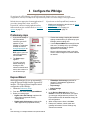
1
iPBridge 2700C/R/D
Installation and Operation Manual
ATTO Technology, Inc.
155 CrossPoint Parkway
Amherst, New York 14068 USA
www.attotech.com
Tel
Fax
(716) 691-1999
(716) 691-9353
Sales support:
[email protected]
Technical support: Monday -- Friday, 8am-8pm EST
[email protected]
© 2007 ATTO Technology, Inc. All rights reserved. All brand or product names are trademarks of their respective
holders. No part of this manual may be reproduced in any form or by any means without the express written
permission of ATTO Technology, Inc.
09/2007 ................................................................................................................................: PRMA 0358-000
Contents
1 ATTO iPBridge provides storage options .......................................1
Embedded software features
Connectivity, infrastructure solutions
1.1 ATTO iPBridge 2700R/D physical components .................3
Dimensions
Environment
Power
Ethernet data ports
Fibre Channel data ports
Management ports
LED indicators
1.2 ATTO iPBridge 2700C physical components ....................5
Dimensions
Environment
Power
Ethernet interface
Fibre Channel interface
Management ports
Reset/restore factory default switch
LED indicators
2 Installation ..........................................................................................7
Unpacking the packing box; verifying contents
Placing the iPBridge into your system
Installing Windows drivers
Discovering the IP address
Installing MS iSCSI Initiator for Windows
Installing iSCSI Initiator for OS X
Setting up Internet Explorer
Beginning initial configuration
3 Configure the iPBridge ......................................................................9
Preliminary steps
ExpressWizard
3.1 Target management .............................................................11
Target names
Default target node
Automatically configure a single target
Map devices manually
Multiple target nodes
Automatically configure multiple targets
Manually configure multiple target nodes
3.2 iSCSI configuration ..............................................................14
Ethernet
iSCSI
CHAP commands
3.3 Optional changes .................................................................15
Preliminary steps
Modify passwords
Set up a VLAN: Virtual Local Area Network
Enhance performance
iSCSI performance configuration tool (Windows only)
4 Remote system monitoring ...............................................................17
SNMP
Email notification
5 Updating firmware .............................................................................19
Using ATTO ExpressNAV
Using FTP
6 Troubleshooting .................................................................................20
Inside out method
Check basic diagnostic tools
Check the host event log
Check the event and trace logs
Visually inspect LEDs
Check for problems on attached devices
Check host versions
Check iPBridge product versions and update firmware
Check components
Check Fibre Channel devices
Check the iPBridge FC ports
Check the serial port
Check iPBridge internal configuration
Check iPBridge Ethernet ports
Check the LAN/WAN
Check the iSCSI Host Adapter or NIC
Check the iSCSI OS driver
Check the Operating System
Performance Issues
Check Fibre Channel devices
Check the iPBridge Ethernet ports
Check the LAN/WAN
Check the Ethernet host adapter or NIC
Check applications
Check the host system
Check the Operating System
Optimize ATTO ExpressNAV in Internet Explorer
Use the ATTO iSCSI performance configuration tool for Windows
Reset/restore factory default
7 Interface options ................................................................................27
Using ExpressNAV
Opening an ExpressNAV session
Optimizing ExpressNAV in Internet Explorer
Using the serial port
Using Telnet
Appendix A CLI provides an ASCII-based interface ...........................i
CLI error messages
CLI summary
Alphabetical CLI command explanations
Appendix B Safety standards and compliances .................................xiv
Appendix C Warranty information ........................................................xvi
Manufacturer limited warranty
1 ATTO iPBridge provides storage options
The ATTO iPBridgeTM 2700C/R/D iSCSI to Fibre Channel bridge offers an affordable opportunity to
transform Fibre Channel storage into network-enabled addressable devices, creating scalable solutions
for an iSCSI SAN.
The iPB2700 is a cost effective, high performance
bridge using four Gigabit Ethernet ports and two
independent 4-Gb Fibre Channel buses.
The iPBridge comes in two form factors:
•
Security thorough Virtual LANs, Access Control
Lists (ACLs) and multiple levels of password
protection.
•
Advanced Diagnostics: includes software eventlogging capability time and date stamped by the
real time clock. You can also determine
numerous status and current configuration
parameters.
Because the iPBridge 2700C/R/D provides a
compact embeddable, rack or desktop solution,
you can install the iPBridge in a wide range of
system configurations. Uniquely designed to
support the high throughput needs for
applications that require streaming data transfers
(data backup), the iPBridge optimizes
performance by using ATTO Technology
intelligent Bridging Architecture.
The iSCSI protocol allows storage devices such as
hard drives, tape drives and libraries and CD
jukeboxes to attach easily to Internet Protocol
networks such as Gigabit Ethernet. The ATTO
iPBridge supports the high throughput needs of
streaming data transfers, optimizing performance
and management using ATTO Technology
intelligent Bridging Architecture™.
•
ATTO ExpressNAV™: a web-based
management application that allows all of the
configurable settings for the iPBridge to be
defined, viewed and edited.
Embedded software features
•
•
•
•
•
4U cPCI embeddable circuit board or blade,
designated as the iPBridge 2700C
a rack mount / desktop version (13”d x 19”w x
1U) designated as the iPBridge 2700R/D
•
ATTO ExpressWizard: a quick way to initially set
up the iPBridge and storage for specific
applications.
•
SpeedWrite™: a performance-enhancing
capability that significantly boosts Write
performance by efficiently managing Write
commands between host and a tape device.
1
ATTO Technology Inc. iPBridge Installation and Operation Manual
Connectivity, infrastructure solutions
The topology of a heterogeneous Storage Area
Network shown below demonstrates the critical
role ATTO products play in the design and
implementation of a SAN. Whether your
application needs are data-intensive or bandwidth intensive, you need to store and manage
that data and then deliver it to end-users
efficiently. ATTO products have been engineered
with the highest performance and lowest cost
available today.
•
•
•
•
4 independent 100/1000 GbE RJ45 Ethernet
ports to 2 optical SFP independent 4-Gb Fibre
Channel ports
Near wire speed (99.35%) per GbE port
Auto negotiates to 4/2/1 Gb Fibre Channel
Full support for direct connect to F-port fabric
switches, FC-AL, PLDA, public loop login and
iSCSI protocol 1.0
intelligent Bridging Architecture, the engine
within ATTO iPBridge™ products, uses ATTO
Data Routing for optimized performance
PCI-X v1.0 internal bus
Fabric topology and ATTO Virtual Device
Manager to optimize performance
Ethernet
Fibre Channel
SCSI
Possible storage
configurations
GbE network
ATTO iPBridge 2700
ATTO Celerity FC
storage adapter
GbE Switch
4-Gb FC Switch
ATTO FibreCenter Hub
ATTO ExpressPCI
FC storage adapter
ATTO FibreBridge 2400
ATTO FibreBridge
embedded
ATTO iPBridge
1500/1550/2500
SCSI Tape Library
SCSI Tape Library
FC model
SCSI model
ATTO Diamond Storage Array
ATTO ExpressPCI
SCSI storage adapter
2
1.1 ATTO iPBridge 2700R/D physical components
The ATTO iPBridge 2700R/D is a 1-Gigabit Ethernet to Fibre Channel 1U full-rack bridge for high
performance, cost effective solutions in enterprise environments.
Dimensions
Width: 17 inches
Length: 8.94 inches
Height: 1.7 inches (1U)
Weight: 8 pounds
The data ports support IP v.4 in compliance with
IEEE 802.3 GbE. Each may also be used for
iPBridge management.
GbE cables must be at least CAT-5E certified for
1000 Mb/sec. use.
Environment
Fibre Channel data ports
The two independent optical SFP 4-Gb Fibre
Channel ports auto-negotiate to 1-, 2- or 4-Gb
devices.
5-40 °C external
Ambient air should not exceed 40 °C
Cooling: air enters through the slots in the rear
panel and exits through the blower on the far end
of the rear panel.
Humidity: 10-90% non-condensing
Operating temperature:
Power
100-260 [email protected] amps. ATTO
Technology, Inc. does not offer specific
international power cords. The power inlet on the
unit is a IEC320-C14. When selecting a cord, be
sure it meets all national safety compliance
requirements.
Power draw:
Battery-backed event log SRAM & Real-TimeClock: A rechargeable Lithium ion battery cell
will hold the memory in a 512KB SRAM for up to
30 days.
WARNING
Risk of explosion if the battery is removed
and/or replaced by an incorrect type.
Dispose of used batteries in accordance
with your local environmental regulations.
If the iPBridge has been disconnected from
power, recharging begins automatically when
power is restored to the system. The battery is
fully charged after 24 hours of continuous power
application.
Ethernet data ports
The four independent 100/1000 Ethernet RJ-45
data ports are labeled Ethernet ports 1, 2, 3 and 4.
3
ATTO Technology Inc. iPBridge Installation and Operation Manual
Management ports
A 100 Mb/sec. Ethernet standard
RJ-45 management port and an
RS-232 serial port provide
support for remote monitoring
and management. The serial port
is set at the factory at 115,200
bps.
1
RX 2
TX 3
4
GND 5
6
7
8
9
LED indicators
From the connector side: (see Exhibit 1.1-2):
lights green to indicate ready,
lights yellow to show a faulted condition, and is
off to indicate not ready.
Ethernet management port: a lighted green LED
shows a valid link; off indicates that no link is
present. A separate blinking yellow LED
indicates activity.
Ethernet ports: a green light on the bicolor LED
indicates 100 Mb/sec. Ethernet speed while a
lighted yellow LED shows 1000 Mb/sec. A
separate solidly lit green LED indicates an active
link, blinking indicates activity and off shows no
link is present.
Fibre Channel ports: A lighted green LED
indicates link; off means no link. A separate green
LED indicates activity if it is lit, no activity if it is
off.
Ready/Fault LED
From the front of the iPBridge (see Exhibit 1.1-1):
is lighted green indicates ready,
lighted yellow shows a faulted condition, and off
indicates not ready.
Power LED lights green to show the power is on.
Ethernet ports: a lighted yellow LED indicates
1000 Mb/sec.; if it is off, it means 100 Mb/sec.
Ready/Fault LED
speed. A separate green LED indicates activity if
it is lit.
Fibre Channel ports: a bicolor LED indicates FC
speed. If it is off, speed is 1-Gb; if it is green, 2Gb, and yellow indicates 4-Gb FC. A separate
green LED indicates activity if it is lit, no activity
if it is off.
Exhibit 1.1-1
iPBridge 2700R/D front label.
Exhibit 1.1-2
Overview of iPBridge 2700R/D from the back (connector) side.
Front label side
Width
17"
th
ng
Le .7"
8
Height
1.7"
air vents
RS-232 (serial) port
GbE ports
10/100 Ethernet port
Fibre Channel ports
for bracket
assembly
power connector
Back (connector) side
4
1.2 ATTO iPBridge 2700C physical components
The ATTO iPBridge 2700C is a 1-Gigabit Ethernet to Fibre Channel embeddable cPCI bridge for high
performance, cost effective solutions in enterprise environments.
Dimensions
Width: 6.193 inches
Length: 6.299 inches
Height of tallest component:
.545 inches
Environment
Operating Temperature: 5-40 °C external
Ambient air: should not exceed 40 °C
User-configurable thermal sensor for automatic
shutdown. Default is 70 °C
Humidity: 10-90% non-condensing
Recommended airflow: 166.25 LFM
Power
The iP2700C
6-pin connection pinouts
board may be
NU 5V GND 5V 5V GND
powered from
1 2 3 4 5 6
the cPCI
backplane
connector or a 6-pin connector.
Input voltage: 5.0V
Power draw: 30 Watts
Battery-backed event log SRAM & Real-TimeClock: A rechargeable Lithium ion battery cell
will hold the memory in a 512KB SRAM for up to
30 days.
WARNING
Risk of explosion if the battery is removed
and/or replaced by an incorrect type.
Dispose of used batteries in accordance
with your local environmental regulations.
If the iPBridge becomes disconnected from
power, recharging begins automatically when
power is restored to the system. The battery is
fully charged after 24 hours of continuous power
application.
Ethernet interface
The four independent 100/1000 Ethernet RJ-45
data ports are labeled Ethernet ports 1, 2, 3 and 4.
5
ATTO Technology Inc. iPBridge Installation and Operation Manual
The data ports support IP v.4 in compliance with
IEEE 802.3 GbE. Each may be used for iPBridge
management. GbE cables must be at least CAT5E certified.
Fibre Channel interface
The two independent optical SFP 4-Gb Fibre
Channel ports auto-negotiate to 1-, 2- or 4-Gigabit
devices.
Management ports
A 100 Mb/sec.
Ethernet standard
RJ-45 management
port and a serial 10pin header provide
support for remote
monitoring and
management. The serial port is set at the factory at
115,200 bps.
Reset/restore factory default switch
To reset the iPBridge, briefly insert a tool in the
hole in the back panel for less than three seconds.
See Exhibit 1.2-1.
To restore factory defaults, insert the tool in the
hole in the back panel for more than four seconds
until the green Ready LED blinks.
LED indicators
On-board LED indicators show through the
faceplate and follow left to right. See Exhibit 1.21.
Fibre Channel ports: A lighted green LED
indicates link; off means no link. A separate green
LED indicates activity if it is lit, no activity if it is
off.
Gigabit Ethernet ports: a green light on the
bicolor LED indicates 100 Mb/sec. Ethernet
speed while a lighted yellow LED shows 1000
Mb/sec. A separate solidly lit green LED
indicates an active link, blinking indicates activity
and off shows no link is present.
Ethernet management port: a lighted green LED
shows a valid link; off indicates that no link is
Exhibit 1.2-1
present. A separate blinking yellow LED
indicates activity.
Ready/Fault: lights green to indicate ready, lights
yellow to show a faulted condition, and is off to
indicate not ready.
iPBridge 2700C faceplate and board configuration
6
2 Installation
If you have not already completed the instructions on the Quick Start packed with your iPBridge, use
the following instructions to install the iPBridge.
Unpacking the packing box; verifying
contents
•
•
•
•
•
The iPBridge
Note the serial number of your iPBridge,
located on the bottom of the unit, for later use:
______________________________
Serial cable
Power cord
“L” brackets and screws
CD which includes the Installation and Operation
Manual, the firmware, ATTO QuickNAV and
ATTO drivers
Placing the iPBridge into your system
1
3
4
5
b. Install the iPBridge horizontally within the
rack so it does not reduce the air flow within
the rack.
Connect the host computer to Fibre Channel
devices.
Power up the Fibre Channel devices.
Connect the iPBridge Ethernet port on the host
computer to your network using at least Cat5e
cable.
Connect the AC power cord from the iPBridge
to the proper AC source outlet.
1
2
3
4
5
6
7
8
1
2
3
4
The power source must be connected to a
protective earth ground and comply with
local electrical codes. Improper grounding
may result in an electrical shock or damage
to the unit.
6
7
7
ATTO Technology Inc. iPBridge Installation and Operation Manual
Windows automatically detects the iPBridge
and asks for the driver in the Add Hardware
wizard. Select Install from a list or specific
location
Click Next
Choose Don’t Search
Click Next
Choose Have disk
Specify the driver as found in the PC folder in
the setup CD. The files are in a folder based on
your operating system. Use the files directly
from the CD or copy them onto a floppy or to a
local directory on your hard drive.
Follow the remaining instructions to complete
the installation procedure.
After the driver is installed, the iPBridge is listed
in the System Devices folder.
Discovering the IP address
CAUTION
If installing into a rack note that the power
requirements plus the power draw of the other
equipment in the rack must not overload the
supply circuit and/or wiring of the rack.
Turn on the power switch on the iPBridge.
Wait up to two minutes for the iPBridge Ready
LED to light indicating the bridge has completed
its power-on self test sequence.
Windows® users continue to Installing
Windows drivers; Mac® users continue to
Discovering the IP address
Installing Windows drivers
Place the iPBridge on a stable flat surface or
install it into a standard rack.
If installing into a rack, see Exhibit 2.0-1.
a. Attach brackets so that the front side with
the LEDs face front and the connector side
is at the back.
2
8
5
From the CD supplied with your iPBridge, run
the QuickNav Utility QuickNAV-windows.exe
for Windows or QuickNAV-Mac for OS X.
Locate the iPBridge with the serial number
recorded earlier.
Highlight the serial number.
Click Next.
If a DHCP server is available on your network,
an address is assigned automatically by the
server. Note the assigned address:
_____________________________________
If you do not have a DHCP server, get an IP
address and subnet mask from your network
administrator, type it into the area provided, and
select Next. Note the IP address and subnet
mask here._____________________________
Click on Launch Browser
Windows users continue to Installing MS iSCSI
Initiator for Windows; Mac users continue to
Installing iSCSI Initiator for OS X.
If you use Internet Explorer, use Setting up
Internet Explorer if needed.
Installing MS iSCSI Initiator for Windows
Setting up Internet Explorer
1
1
2
3
Download the latest version of Microsoft® iSCSI
Software Initiator from
www.microsoft.com/downloads. Searching
2
3
4
5
6
7
8
9
10
11
12
13
on iSCSI Initiator helps to locate it.
Launch the Initiator installation program and
follow the instructions.
Find the Microsoft iSCSI Initiator icon on your
desktop and launch the program.
Click on the Discovery tab.
Click on the Add button under the target portal
heading.
Type in the iPBridge IP address recorded in
Discovering the IP address on page 7.
Click on OK
Click the Targets tab.
Click on Log on button.
Select Automatically restore
Click OK to complete logon.
If the Found New Hardware Wizard appears,
follow the instructions and install the driver from
the CD that came with your iPBridge.
Click OK to close the iSCSI Initiator utility.
You should now have storage you can manage
through Windows Disk Management.
Continue to Beginning initial configuration.
Installing iSCSI Initiator for OS X
Contact your ATTO sales representative or go to
www.attotech.com to purchase the ATTO
Technology Xtend SAN, iSCSI Initiator for OS
X.
Exhibit 2.0-1
Open your browser
Select Internet Options.
In the Internet Options screen, select the
Security tab.
4 Click on the Trusted Sites icon.
5 Click on the Sites button.
6 In the text box Add this Web site to the zone,
add the IP address of the iPBridge. You may
use wild cards.
7 Click on Add
8 Uncheck the Require server verification
check box.
9 Click OK.
10 At the bottom of the Internet Options box, click
on OK and close the box.
Beginning initial configuration
1
2
Return to the ExpressNAV interface welcome
screen. Click on Enter Here
Type in the user name and password.
Note
The default values are user name root and
password Password. The user name is case
insensitive and the password is case
sensitive.It is best practice to change the
default user name and password. Refer to
Modify passwords on page 15.
3
The Status page appears. Continue to
Configure the iPBridge on page 9.
Install the iPBridge into a rack using the brackets provided.
iPBridge front
(supplied by ATTO)
Rack
(supplied by ATTO)
8
3 Configure the iPBridge
To configure the ATTO iPBridge, use ATTO ExpressNAV. Default values are appropriate for most
configurations, but may be modified.The ExpressWizard provides one-button setup for many applications.
Default values are appropriate for most applications. If
you wish to change these values, use ATTO
ExpressNAV, a browser-based graphical interface.
Other methods are also available. Refer to Interface
options on page 27.
If you do not use the ExpressWizard, continue to
•
•
•
Mapping and addressing, also known as Target
management on page 11
iSCSI configuration on page 14
Optional changes on page 15
Preliminary steps
1
2
If you are not already in
the ExpressNAV
interface, type the IP
address of your
iPBridge in a standard
browser as found in
Using ExpressNAV on
page 23, click Enter
Here, type in your user
name and password,
and click OK.
The Status page
appears.
You may view the
default settings by
clicking on each
element in the left hand
menu, then continue in
one of three ways:
•
Review the settings, keeping the automatic
settings created when you powered up your
iPBridge and do nothing now.
• Use the ExpressWizard, accessed from the
side menu, to initially set up your iPBridge
and its attached storage for specific
applications automatically.
• Use the individual pages listed on the side
menu to make changes or use other features
as needed.
ExpressWizard
Most applications may be set up automatically
using the ExpressWizard from the ExpressNAV
interface. The ExpressWizard simplifies initial
configuration of the iPBridge
1
2
3
Follow the Preliminary steps.
From the side menu select ExpressWizard.
Select your storage type
• Digital video disk storage: optimized for
digital video (sequential access)
configurations
• Digital audio disk storage: optimized for
audio applications (sequential access)
9
ATTO Technology Inc. iPBridge Installation and Operation Manual
•
4
5
6
7
IT/database disk storage optimized for
general IT and database applications
(random access).
• Tape storage
• Optical storage
Click Next.
In the Devices Detected page, click on
Rescan to ensure all the devices you wish in
your storage configuration are present. The
ExpressWizard uses all attached storage for
the configuration.
When all devices are listed, click Next.
Data port IP address, subnet mask and
gateway information is listed. Change any
elements as needed.
8
9
Click Next.
Select the answer to the question Does your
network support Jumbo Frames?
10 Click Next.
11 Set your administrator password.
12 Click Next.
13 The configuration for the iPBridge based on
your input in the previous screens appears. If
the information is correct, click Commit.
14 The ExpressWizard configures your iPBridge
and storage. You may select items on the left
side menu to view the current configuration or
to change the configuration.
10
3.1 Target management
Storage devices are mapped using the designations for the iSCSI LUN. The easiest way to map devices
is to use the Automatic Target Management feature in the ATTO ExpressNAV interface.
CAUTION
•
Changing the device map can affect the
host’s view of devices and your application
configuration
To map Fibre Channel devices, you must connect
the devices to one of the iPBridge Fibre Channel
ports. To access mapped Fibre Channel devices
over Ethernet, you must have a host computer
connected to one of the iPBridge Ethernet data
ports.
The default is set up as a single target node in
which a host or initiator views the iPBridge as a
single iSCSI node with all available devices
shown as LUNs on a single iSCSI target.
If you decide to change the automatic mapping set
up when you powered up the iPBridge, you have
two options to map devices after you disable
automatic mapping:
•
You may map devices manually to the single
default node.
You may map each device to its own target to
break the single iSCSI target node into multiple
nodes. Multiple target nodes allow greater
flexibility to grant or deny access between
initiators and devices.
If you divide the default single target node into
multiple target nodes, you must set up access to
each node separately.
See Exhibit 3.1-1 on page 13 to see the difference
between single target node and multiple target
nodes.
Target names
Each iSCSI target node accessed through the
Ethernet port on an iPBridge is identified by a
unique world-wide iSCSI-qualified name. This
format references the iPBridge serial number and
target node name:
iqn.1995-12.com.attotech:ipbridge:
serialnumber <targetname>
Default target node
The default target is set as a single target with
Access Control (ACL) disabled and CHAP
authentication disabled. The default target node
cannot be deleted. The iPBridge maps devices
automatically although you can map devices
yourself.
4
Automatically configure a single target
Map devices manually
1
1
2
3
If you are not already in the ExpressNAV
interface, type the IP address of your iPBridge
in a standard browser as found in Using
ExpressNAV on page 23, click Enter Here,
type in your user name and password, and click
OK.
The Status page appears. From the
ExpressNAV menu, select Auto Target Mgt.
Click on the Map all devices to default target
button.
11
ATTO Technology Inc. iPBridge Installation and Operation Manual
2
When the action is complete, the iSCSI Target
Management page appears. Make any
adjustments to the mapping or begin a
discovery session.
If you are prompted to restart the iPBridge, go
to the Firmware Restart page and restart the
iPBridge.
If you are not already in the ExpressNAV
interface, type the IP address of your iPBridge
in a standard browser as found in Using
ExpressNAV on page 23, click Enter Here,
type in your user name and password, and click
OK.
The Status page appears. Select the Manual
Target Mgt menu item on the left side of the
screen.
3
4
Click on the Device Maps link of the default
target.
Select the devices from the box on the right
hand side of the screen and drag to the
appropriate LUN on the left.
5
Click Submit.
If you are prompted to restart the iPBridge, go
to the Firmware Restart page and restart the
iPBridge.
1
The Status page appears. Click on the Auto
Target Mgt menu item on the left side of the
screen.
Click on the Map each device to its own
target button.
A target name suffix will be added to the iqn of
each Fibre Channel device such as
Multiple target nodes
Multiple targets allow you to create a more
configurable mapping scheme which can
segregate storage into different iSCSI nodes
within the iPBridge, with each iSCSI target
having its own set of access criteria.
For example, if you have two servers and a library
with four tapes and a media changer, the default
node would provide both servers access to all
tapes and the media changer (default target
mode).
If you configured multiple target nodes, you are
able to map some devices to one server and other
devices to the other server, requiring separate user
names and passwords for access using various
methods including Access Control Lists, iSNS
and CHAP authentication. Consult with your
network administrator and refer to Exhibit 3.1-1.
Note
If actual storage is mapped to more than one
iSCSI target and a server has authorization for
both targets, the server could show duplicate
storage without any warning to the user.
2
vendorid-devicename-xxx
•
vendorid is the Fibre Channel device
vendor ID
• devicename is the Fibre Channel device’s
inquiry device name.
• xxx is a device index
When the action is complete, the screen will go
to the iSCSI Target Management page.
If you are prompted to restart the iPBridge, go
to the Firmware Restart page and restart the
iPBridge.
Manually configure multiple target nodes
1
You may use either of two methods to control
access to storage: Access Control Lists or CHAP
authentication.
Access Control lists: each target iqn has its own
access control. The iPBridge will check the
initiator’s iqn before allowing access.
CHAP to control access: different CHAP
account names and CHAP secrets are assigned to
each target.
2
Automatically configure multiple targets
6
7
1
If you are not already in the ExpressNAV
interface, type the IP address of your iPBridge
in a standard browser as found in Using
ExpressNAV on page 27, click Enter Here,
type in your user name and password, and click
OK.
3
4
5
8
If you are not already in the ExpressNAV
interface, type the IP address of your iPBridge
in a standard browser as found in Using
ExpressNAV on page 27, click Enter Here,
type in your user name and password, and click
OK.
The Status page appears. Select the Auto
Target Mgt menu item on the left side of the
screen.
In the iSCSI Target Management page, type
[name] in the Add an iSCSI target box
The name is a suffix appended to the standard
IPBridge iqn name. The suffix name can be up
to 24 characters.
Click on the device map link of your target.
After the next mapping page opens, drag the
boxes representing devices to the LUNs you
want.
Click Submit.
Repeat from Step 3 for each node you want to
configure.
If you are prompted to restart the iPBridge, go
to the Firmware Restart page and restart the
iPBridge.
12
Exhibit 3.1-1
Target node configurations.
13
ATTO Technology Inc. iPBridge Installation and Operation Manual
3.2 iSCSI configuration
You may fine-tune the iPBridge using the ATTO ExpressNAV interface.
Several special iPBridge features may be
accessed using the ExpressNAV graphical user
interface. For details on each command, refer to
CLI provides an ASCII-based interface on page
i of the Appendix
1
If you are not already in the ExpressNAV
interface, type the IP address of your iPBridge
in a standard browser as found in Using
ExpressNAV on page 27, click Enter Here,
type in your user name and password, and click
OK.
2 The Status page appears. Click on the menu
item which regulates the parameter you wish to
change.
• Ethernet: iSCSI port number
• iSCSI iSCSI Alias, ISNS Login Control,
iSNSServer, Speedwrite
• CHAP commands: iSCSI Chap Secret, iSCSI
Target through the Manual Target Mgt
menu
3 Click Submit on each page after you have
made changes to save your choices. When you
have completed all changes, go to the Restart
page and click on Restart.
Ethernet
Click on the Ethernet menu item.
iSCSI Port Number
Specifies the port number whereby the iPBridge listens
for iSCSI connections. The port number must be between
1024 and 65535 except for port 860. The default is 3260.
iSCSI
Click on the iSCSI menu item.
iSCSI Alias
Provides a human-readable name assigned to the
iPBridge. Aliases may be 1 to 64 characters long and may
contain spaces if spaces are enclosed in quotation
marks. The default is a blank space.
iSNS Login Control
Specifies whether the iPBridge will delegate its access
control/authorization to an iSNS server. Default is
disabled.
Note
iSNS Login Control cannot be used with
Access Control found on the iSCSI Target
Management page.
iSNSServer
Specifies whether the IP address of a valid iSNS server
from which the iPBridge will attempt iSCSI initiator
discovery. Setting to 0.0.0.0 disables the iSNS server
lookup. Default is 0.0.0.0.
SpeedWrite
When enabled, improves the performance of WRITE
commands to devices attached to the iPBridge.
CHAP commands
To find the CHAP commands,
1
2
3
Click on the Manual Target Mgt menu item
Click on the Target Management page
Click on the iSCSI CHAP table entry next to the
iSCSI target you wish to use.
iSCSI CHAP
iSCSI CHAP controls whether CHAP (Challenge
Handshake Authentication Protocol) is used for the iSCSI
protocol. If CHAP is enabled, the target requires the
initiator to negotiate CHAP authentication using CHAP
secrets (passwords). An initiator may reject this
negotiation.
iSCSI Chap Secret
Specifies the incoming and outgoing secrets (passwords)
for iSCSI CHAP sessions. Secrets are case sensitive, 12
to 32 characters (16 for Microsoft iSCSI initiator), and
cannot contain spaces. In and out secrets must be
different.
An in secret is for authentication of the server to the
iPBridge. The iPBridge can store up to 32 in secrets.
An out secret is for authentication of the iPBridge to the
server. There is only one out secret per target that cannot
be deleted.
iSCSI Target
Creates or deletes an iSCSI target name. The target
name acts as a suffix to the standard bridge iSCSIqualified name. The target name may not exceed 24
characters.
14
3.3 Optional changes
Default values, even if you have not used the ExpressWizard, are appropriate for most configurations,
but may be modified.
Preliminary steps
1
If you are not already in the ExpressNAV
interface, type the IP address of your iPBridge
in a standard browser as found in Using
ExpressNAV on page 27, click Enter Here,
2
Modify passwords
1
2
Follow the Preliminary steps
Click Bridge.
The Bridge Configuration page is displayed.
3
4
5
6
type in your user name and password, and click
OK.
The Status page appears.
View the default settings by clicking on each
element in the left hand menu, then use the
individual pages listed on the side menu to
make changes or use other features.
Enter the Administrator (Admin) password
where indicated.
Enter appropriate information into the New
Admin Password, Confirm New Admin
Password or New Read Only Password and
Confirm New Read Only Password text
boxes.
Click Submit.
Go to the Restart page and restart the
iPBridge.
The Administrator user name that you are
currently logged in with and the current read
only user name, if present, are displayed in
their text boxes.
Set up a VLAN: Virtual Local Area Network
A Virtual LAN (VLAN) is a group of devices on
the same physical LAN which can communicate
with each other as if they were all on different
physical LANs. This creates a network that is
independent of physical location, allows grouping
of users into logical workgroups, increases
efficient use of resources, and adds security
options by allowing some users into the LAN and
keeping other users out.
You may create up to eight Virtual LAN IDs for
each Ethernet data port. Each VLAN ID is
15
ATTO Technology Inc. iPBridge Installation and Operation Manual
assigned a VLAN name of up to 64 characters. If
no VLAN Id exists for a data port, VLAN is
disabled for that port.
1
2
3
4
5
Follow the Preliminary steps
Click on the Ethernet menu item.
The Ethernet Port Configuration page
appears. Add a VLAN ID number and name in
the appropriate boxes.
Press Submit.
Go to the Restart page and restart the
iPBridge.
After rebooting, Virtual LAN takes effect.
Enhance performance
Note
If you used ExpressWizard to set up your
iPBridge, changing these parameters may
interfere with ExpressWizard settings.
Default values, even if you have not used the
ExpressWizard, are appropriate for most
configurations, but may be modified.
1
2
3
Follow the Preliminary steps.
On the iSCSI page, enable SpeedWrite.
On the Ethernet page, change MTU to 9014.
Note
If you change the MTU on the iPBridge, you
must enable jumbo frames on your initiator
and change the MTU on the initiator.
4
For Windows operating systems, use the ATTO
iSCSI performance configuration tool
(Windows only).
MaxBurstLength
The maximum data payload, in bytes, in a Data-In or a
solicited Data-Out iSCSI sequence. A sequence consists
of one or more consecutive Data-In or Data-Out PDUs
that end with a Data-In or Data-Out PDU with the F bit
set to one.
ATTO value: 1048576 decimal 00100000 hex
MaxRecvDataSegmentLength
The maximum data segment length, in bytes, that a
transmitter (initiator or target) can receive in an iSCSI
PDU. The transmitter is required to send PDUs with a
data segment that does not exceed
MaxRecvDataSegmentLength of the receiver.
ATTO value: 1048576 decimal 00100000 hex
MaxTransferLength
The maximum number of bytes that may be transferred by
a single request block (SRB).
iSCSI performance configuration tool
(Windows only)
The ATTO iSCSI performance configuration tool
changes the Windows registry parameters for
Microsoft iSCSI Initiator and TCP/IP to enhance
overall data throughput.
ATTO value 1048576 decimal 00100000 hex
1
Tcp1323Opts
This parameter controls RFC 1323 time stamps and
window-scaling options. Time stamps and window
scaling are enabled by default, but can be manipulated
with flag bits. Bit 0 controls window scaling and bit 1
controls time stamps.
2
3
From the CD which came with your iPBridge,
copy the Perftune.exe file to your hard drive.
Execute the program.
Click on Use ATTO Performance Settings.
Settings take effect on the next system reboot.
The following settings are affected:
FirstBurstLength
The maximum amount, in bytes, of unsolicited data an
iSCSI initiator may send to the target during the
execution of a single command including the immediate
data and the sequence of unsolicited Data-Out PDUs
which follow the command. FirstBurstLength cannot
exceed MaxBurstLength
SrbTimeoutDelta
The maximum amount of time, in seconds, before an SRB
request will time out.
ATTO value 300 decimal 0000012c hex
ATTO value: 1
ATTO value: 1048576 decimal 00100000 hex
16
4 Remote system monitoring
You may set up the iPBridge to send notifications when certain events occur.
You may set up the iPBridge to send notifications
when certain events occur using the Remote
Management page of the ExpressNAV
interface.
You designate the person receiving notification of
conditions and the level of severity which prompt
notification using the Simple Network
Management Protocol (SNMP) or Email
notification.
For both methods, the severity level which is
report can be critical, warning or all.
•
•
•
Critical means only critical event notifications
are sent.
Warning means only warnings and critical event
notifications are sent.
All means warnings, critical events and
informational messages are sent.
SNMP
An agent resides in the iPBridge which takes
information from the iPBridge and translates it
into a form compatible with SNMP. If certain
conditions arise, the agent sends notifications
(traps) to a client.
Contact your network administrator for the MIB
software and appropriate MIB file for your
iPBridge.
1 Follow the Preliminary steps on page 15.
2
3
In the SNMP line, click on the enabled button.
Click on Remote Mgt from the side menu. The
Remote Management page appears.
4
In the SNMP Traps or SNMP Extended Traps
line, click on Enable. For details, refer to SNTP
and SNMPExtendedTraps on page xii of the
Appendix.
5 In the SNMP Trap Recipient IP addresses
section, enter the IP address of each person you
want to notify.
17
ATTO Technology Inc. FastStream 5300 Installation and Operation Manual
6
From the drop-down box next to each trap
address, select the level of severity for which
you want each address to be notified: None, All,
Critical or Warning.
7
8
Click on Submit.
Go to the Restart page and restart the iPBridge.
After rebooting, the iPBridge sends notifications
as you set them up.
3
Click on the Enabled button for Email
Notification
4
Type in the sender address (Emails show this
name in the From field)
Type in the SMTP Server IP Address
Type in the user name and password of your
SMTP Email account
Type in up to five Email addresses
From the drop-down box, choose None, All,
Critical or Warning for each Email address.
Click on Submit.
Go to the Restart page and restart the
iPBridge. After rebooting, the iPBridge sends
notifications as you set them up.
Email notification
Email notification allows the iPBridge to send an
Email message to you, a network administrator or
other users when certain events occur with the
iPBridge. Serious error messages are sent
immediately, while messages for less serious
errors are sent every 15 minutes.
You may send Emails to up to five Email
addresses and designate which conditions prompt
each Email notification.
For example, a recipient with a critical severity
level only receives critical messages and not
warning or informational messages.
When an event occurs that warrants Email
notification, the iPBridge sends the message; it
cannot respond to a rejection by a server for an
invalid address. Ensure all Email addresses typed
in are valid.
1 Follow the Preliminary steps on page 15.
2
Click on Remote Mgt from the side menu. The
Remote Management page appears
5
6
7
8
9
10
18
Remote management
5 Updating firmware
Several processors control the flow of data in the ATTO iPBridge. The firmware to control these
processors can easily be upgraded in the field.
The iPBridge firmware is distributed as an .ima file
can be obtained from the ATTO Technology, Inc. web
site at www.attotech.com or from the CD included
with your iPBridge.
CAUTION
Using ATTO ExpressNAV
1
2
3
Before beginning this procedure, ensure
that all I/O to the iPBridge has stopped.
During this procedure, do not interrupt the
flash process.
If you have not already, open an ExpressNAV
session. For instructions, refer to Opening an
ExpressNAV session on page 27.
Click on the Firmware page.
Click Browse and locate the firmware you
downloaded from the website or from the CD.
A sample filename:
c:\bridge_firmware\ibrg0370.ima
4
Click Upload and wait until a success message
is displayed.
Click the Restart link.
Click on Restart.
Do not power down the host or the
iPBridge until the display returns the
Ready prompt.
5
6
Interrupting the flash process will make
your iPBridge inoperable and you must
return it to ATTO Technology for repair.
Using FTP
1
2
Establish an FTP link to the bridge that is to be
flashed.
Use the PUT command to download the
firmware file. A sample filename:
c:\bridge_firmware\ibrg0370.ima
3
19
ATTO Technology Inc. iPBridge Installation and Operation Manual
Once the download is complete, cycle power on
the iPBridge to activate the new firmware.
6 Troubleshooting
If it is clear that a particular component system is at fault in a problem situation, go directly to that
component. If it is not clear, the best approach is to troubleshoot using the inside-out method.
You may check on the status of your iPBridge
using the ExpressNAV interface. Refer to Using
ExpressNAV on page 27. You may also look for
information by using the diagnostic CLI
commands, in the Advanced page of the
ExpressNAV interface, or by using the CLI
directly (refer to CLI provides an ASCII-based
interface on page i of the Appendix.
Inside out method
To troubleshoot using the inside out method, begin with the device(s) connected to the iPBridge first,
then work your way out:
•
Fibre devices
• iPBridge Fibre ports
• iPBridge internal configuration
• iPBridge Ethernet/IP ports
• LAN/WAN
• Ethernet host adapter or NIC in host
• Initiator
• OS
• Application
Check basic diagnostic tools
Check the host event log
Check the event log on the host. Look for the most
recent entries and determine what could be
causing a problem, then go to that event and
continue troubleshooting.
Check the event and trace logs
Check the iPBridge event log through the
Advanced page of the ExpressNAV interface or
through CLI. Look for the most recent entries and
determine what could be causing a problem. Then
go to that event and continue troubleshooting.
Visually inspect LEDs
If a non-fatal power supply problem occurs, or if
a problem is detected before shut down occurs,
the bicolor Ready/Fault LED flashes on the front
and back (connector) sides of the iPBridge
2700R/D and on the front faceplate of the
iPBridge 2700C. The Fault LED also flashes
briefly during start up. Off means not ready,
green on means ready, and yellow on means
faulted.
Inspect the iPBridge 2700C faceplate and
iPBridge 2700R/D back (connector side) LEDs
(see Exhibit 6.0-1 and Exhibit 6.0-2):
•
•
•
•
•
a lighted green LED, embedded in the connector
of the Ethernet management port, indicates a
valid link. Off shows that no link is present.
a blinking yellow LED, embedded in the
connector of the Ethernet management port,
indicates activity.
a bicolor LED, embedded in the connector on
each Gigabit Ethernet port, indicates 100/1000
Mb/sec. speed. Green on indicates 100 Mb/sec.
and yellow on indicates 1000 Mb/sec.
a green LED for each Gigabit Ethernet port
indicates link/activity, where on solid indicates
link, blinking indicates activity and off is no link is
present.
a green LED for each Fibre Channel port
indicates link where off means no link.
20
•
a separate lighted green LED for each Fibre
Channel port shows activity and an unlit LED
means no activity.
Inspect the front side LEDs (iPBridge 2700R/D
only) (see Exhibit 6.0-2):
•
•
•
•
•
a green power LED; on means power is on; off
means power is off.
a yellow LED on each Ethernet port indicates
100/1000 Mb/sec. speed, where off means 100
Mb/sec. and on means 1000 Mb/sec.
a green LED on each Ethernet port activity,
where off means no activity and on means
activity.
a bicolor LED on each Fibre Channel port
indicates FC speed. Off is 1G FC, green is 2G
FC and yellow indicates 4G FC.
a green LED on each Fibre Channel port
indicates activity, where off means no activity
and on means activity.
Check for problems on attached devices
Check the following in order to find problems on
attached devices:
•
•
•
•
LEDs
Display panels
Firmware levels
Operability
Exhibit 6.0-1
Exhibit 6.0-2
•
•
•
•
•
•
Operating system version
Service pack version
Host adapter version
Host adapter firmware version
Host adapter device driver version
iSCSI driver version
If an update is required, perform the update. For
an updated list of supported iPBridge host
platforms and host adapters, visit
www.attotech.com.
Check iPBridge product versions and
update firmware
1
2
3
Enter ATTO ExpressNAV.
Check the version numbers on the Status
page.
For a current list of updates, visit
www.attotech.com.
4
If an update is needed, download the update
from www.attotech.com.
Go to the Firmware Update page in ATTO
ExpressNAV and follow the instructions in
Updating firmware on page 19.
If the update does not work, use the FTP method
to download the firmware update and verify that
your FTP client is set for binary mode
iPBridge 2700C faceplate
Fibre Channel ports
LEDs
Check host versions
Check the following to find problems on attached
hosts:
GbE ports
FC Link FC Activity GbE Speed GbE Activity
iPBridge 2700 R/D front label
21
ATTO Technology Inc. iPBridge Installation and Operation Manual
10/100
Ethernet port
Link Activity
Reset
button
Ready/Fault
Check components
Use this procedure to check system components.
For more information on the commands used in
this procedure, refer to CLI provides an ASCIIbased interface on page i of the Appendix.
Check Fibre Channel devices
1
2
3
4
5
Check Fibre Channel device power. Make sure
the devices are powering up.
Watch the drive lights before, during, and after
startup.
Check cable integrity. Check the cables for
solid connections.
If the problem persists, try drives one at a time
with different cables, adding drives and cables
until the problem occurs. This helps pinpoint the
drive or cable causing the problem.
Check with the manufacturer of the device(s)
for further troubleshooting methods.
If Fibre Channel devices appear to be working
order, move on to the iPBridge Fibre Channel port
section.
Check the iPBridge FC ports
1
2
3
Either through the ATTO ExpressNAV or CLI,
check the devices on each port.
If no devices appear, re-check cables. If
garbage information appears, the problem is
most likely a bad cable.
Check the internal cabling of the device.
If all devices appear, invoke the FCTargets
command several times on each port to verify
that the devices can be seen. If devices appear
and disappear, then appear again, the problem
is most likely a cable. For information on the
FCTargets command, refer to FCPortList on
page viii of the Appendix.
If all devices appear and remain, move to the
iPBridge internal configuration section.
When changing any setting on the iPBridge, the
configuration must be saved by clicking on the
Save button on the ATTO ExpressNAV interface
screen
or using the saveConfiguration CLI command.
Check the serial port
1
Verify you have the correct settings and that
your terminal is configured to:
• Baud rate: 115200
• Data bits: 8
• Stop bits: 1
• Parity: off
• Flow control: None
• Echo: off
2 Verify that your serial cable is less then two
meters in length.
Check iPBridge internal configuration
Verify that the Fibre Channel devices are mapped
properly using the ATTO ExpressNAV interface.
If devices do not appear, power down the
iPBridge and power back on. Refer to Using
ExpressNAV on page 27 and Target
management on page 11.
When changing any setting on the iPBridge, the
configuration must be saved by clicking on the
Save button on the ATTO ExpressNAV interface
screen or using the saveConfiguration CLI
command.
Check iPBridge Ethernet ports
1
2
3
4
Check Ethernet cable integrity. Check the
cables for solid connections. Cat5 cable can
cause connection issues with Gigabit Ethernet.
Cat5E and Cat6 cable are the best cabling for
the iPBridge.
Verify the IP address, subnet mask, and
gateway are properly set on each data port on
the iPBridge for your network environment.
Refer to Using ExpressNAV on page 27.
Verify that the Ethernet speed is set to auto:
check the Ethernet page of the ATTO
ExpressNAV interface, or check the LED link
lights to determine if the Ethernet speed is
correct. Refer to Visually inspect LEDs on page
20.
Determine if the iPBridge is set to get its IP
information from a DHCP server. If so, verify
that the DHCP server has available IP
addresses.
22
5
Verify that each used Ethernet port on the
iPBridge can be pinged from the desired host.
Refer to Ping on page x of the Appendix.
If the host cannot ping the iPBridge ports and
the iPBridge ports are properly configured,
continue to the Local Area Network/Wide Area
Network section, Check the LAN/WAN on page
23.
Verify that each port on the iPBridge can ping
each desired host. Refer to Ping on page x of
the Appendix. If the iPBridge cannot ping the
host, continue to Check the LAN/WAN on page
23.
6 If using DHCP (the default), verify that the
DHCP server is assigning the correct IP
information to the host.
7 Verify VLAN IDs are either disabled or are set
up identically on the iPBridge and the
connecting switch.
8 Some older switches/hosts cannot auto
negotiate between the iPBridge and the
switch/host at the desired speed. You may
have to force the host/switch or the iPBridge to
the desired speed.
9 Verify that the host is logging into the iPBridge
correctly by viewing the Connections page
and determining if there a “session open”
status.
10 Verify that you are using the correct login
procedure for your initiator. For example: When
connecting using the Adaptec initiator, the log
on screen requests the iPBridge iqn (iSCSI
qualified name). If left blank, Adaptec will not be
able to log in. Enter “iSCSI” into this field for
auto iqn discovery.
Check the iSCSI Host Adapter or NIC
iSCSI host adapters appear as a type of Storage
Controller to the host OS, not as a standard NIC.
These adapters usually have hardware
acceleration to offload the TCP processing from
the host. Configuration of these adapters is
usually done through the vendor’s own utility and
not through the OS itself.
NICs come in two types: accelerated and unaccelerated. Accelerated NICs use some hardware
to offload some of the TCP processing from the
host. Un-accelerated NICs make the OS do all
TCP processing.
To check the iSCSI host adapter or NIC
1
2
3
4
5
6
Check cable integrity. Check the cables for
solid connections. Make sure they are plugged
in properly. Inspect cable ends for broken clips
and improper wiring.
Verify that the iSCSI host adapter or NIC is
configured with the correct IP information.
If using DHCP, verify that the DHCP server is
assigning the correct IP information to the host.
Verify that the hosts are running the
recommended driver and firmware level for the
iSCSI host adapter or NIC vendor.
Verify that the hosts and the iPBridge Ethernet
port in use are using the same port number to
communicate iSCSI. Check the ATTO
ExpressNAV iSCSI page. The default port
number for all ports on the iPBridge is 3260.
Make sure the host adapter/NIC is configured
to log into the iPBridge. Some iSCSI host
adapters do not re-login upon reboot or
unplug/replug event without marking a check
box.
Some older switches cannot autonegotiate
between the host and the switch properly. You
could have to force the host or switch to the
desired speed.
When changing any setting on the iPBridge, the
configuration must be saved by clicking on the
Save button on the ATTO ExpressNAV interface
screen or using the saveConfiguration CLI
command.
7
Check the LAN/WAN
For a NIC using an OS iSCSI driver, continue to
the iSCSI OS driver section.
1
2
3
Verify that the switch/switches are segmented
properly so that hosts and the iPBridge have
access to each other.
If there are routers involved in the setup, make
sure the IP addresses and/or MAC addresses
of the iPBridge are allowed through the router.
Verify that the switch can see the iPBridge on
the port(s) in question. Refer to your switch
vendor’s guide for more information.
23
ATTO Technology Inc. iPBridge Installation and Operation Manual
Check the iSCSI OS driver
If the host uses a driver that allows the OS to talk
to iSCSI targets via a NIC, not an iSCSI storage
adapter:
1
A PC using an iSCSI storage adapter and an
iSCSI OS driver might not work correctly on the
2
3
4
5
6
7
8
same machine. Check with the vendors to
make sure they are compatible.
Verify that the PC has the latest iSCSI driver as
well as the required service packs and patches.
Check with the iSCSI OS driver vendor for more
information.
Verify that the iSCSI OS driver has started.
Look under Device Manager for Windows or
lsmod for Linux.
Verify that the iSCSI OS is still looking for the
iPBridge at the right IP address.
If using DHCP, verify that the DHCP server is
assigning the correct IP information to the host.
Verify that the NIC is configured with the correct
IP information.
Verify that the hosts and the iPBridge are using
the same port number to communicate iSCSI
on the ATTO ExpressNAV iSCSI page. The
default port number for the iPBridge is 3260.
Check cable integrity. Check the cables for
solid connections. Make sure they are plugged
in properly. Inspect cable ends for broken clips
and improper wiring.
Check the Operating System
1
2
3
Verify that the OS has the required service
packs or patches installed. If not, obtain the
proper service packs and patches and install
them.
Some iSCSI host adapters and iSCSI OS
drivers do not always automatically find new
targets when plugged in or when forced to
rescan. Reboot the hosts.
Check if the vendor has a new driver. If so,
install it.
Check the applications
1
2
Verify that the application is running the latest
device drivers for the devices connected to
iPBridge. If not, get the latest device drivers and
install them.
Verify with the application vendor if the iSCSI
technology is supported on the version of the
application being used.
Performance Issues
If the host is not getting the performance it should,
check the following items.
Check the LAN/WAN
1
Check Fibre Channel devices
Verify that the devices are running at their highest
possible speed. Refer to FCDataRate on page vii
of the Appendix.
Check the iPBridge Ethernet ports
1
2
3
Verify that the data port is set to auto negotiate
or forced to 1000 Mb/sec. on the ExpressNAV
Ethernet page.
Verify that the MTU size is set to optimal setting
for the LAN/WAN environment. 9k frame size is
the current optimized frame size for the
iPBridge.
Verify that the iPBridge TraceLog feature is
disabled. Tracelog tracks certain events that
occur in the iPBridge. With this log enabled,
performance suffers. Refer to TraceLog on
page xii of the Appendix.
2
3
Verify that the MTU size is set to optimal setting
for the LAN/WAN environment on the ATTO
ExpressNAV Ethernet page.
9k frame size is the current optimized frame
size for the iPBridge. Many switch and router
vendors do not support the larger frame size of
9k or 16k.
Verify that each associated port in the IP SAN
is configured for 1000Mbs.
IP SAN traffic should be segmented so that it
does not interfere with the main LAN network
traffic.For better performance, the IP SAN
should be on its own set of hardware.
Verify that packets are not being dropped along
the LAN/WAN. Many utilities track packet
activity and switch statistics.
Check the Ethernet host adapter or NIC
Ethernet storage adapters generally outperform
accelerated NICs and un-accelerated NICs by
offloading most of the processing from the host.
An accelerated NIC provides some offloading,
but still requires a host OS iSCSI driver, making
the host spend more CPU cycles.
24
An un-accelerated NIC does not offload anything
so the CPU must do much of the processing.
1
2
3
Verify that the adapter or NIC is sent to autonegotiate or forced to 1000 Mbs.
Set the MTU size to the largest MTU size
supported in the LAN/WAN using the Ethernet
page in the ATTO ExpressNAV interface.
9k frame size is the current optimized frame
size for the iPBridge. Many switch and router
vendors do not support the larger frame size of
9k or 16k.
Set the maximum transfer size to the most
efficient size for the intended target(s). For
many tape drives, 64k is the optimal setting.
Check applications
Some applications can be configured to change
transfer sizes. Configure the application for the
optimal size for the particular device(s) connected
to the iPBridge.
Check the host system
The faster the host, the faster your transfer times
will be. The work flow goes only as fast as the
slowest connection in the host system, so
transferring data from an IDE drive, 100Mb
connection, a DLT 4000, a high speed RAID
volume across the country, or other applications,
slows the system no matter how fast everything
else is in the system.
1
Verify that the iSCSI storage adapter or NIC is
connected to the fastest PCI bus connector
supported by the adapter or NIC.
If the adapter supports PCI-X, place the
adapter in a PCI-X slot. If one is not available,
the host might not achieve the optimal
performance capable from the adapter.
2
Even placing a PCI-X adapter into a 64 bit 66
MHz slot loses performance. Some adapters
adjust clock speed depending on the speed of
the PCI slot into which they are plugged.
The host OS disk and swap disk/partition/file
should be on a high speed drive to minimize the
time needed to access the host’s virtual
memory.
The more memory a system has, the less time
it spends accessing virtual memory (hard drive
space).
Check the Operating System
If possible, eliminate swap space and virtual
drives which require large amounts of system
memory. However, the OS might not allow the
elimination of swap space. An OS set to run many
kinds of different servers spends much of its CPU
cycles on other operations, thus slowing down
performance.
Optimize ATTO ExpressNAV in Internet
Explorer
1
2
3
4
5
6
Go to the browser toolbar and select Tools
Select Internet Options
Select the Security tab
Select the Custom Level button.
On the menu presented, go to the Microsoft
VM, Java permissions and make sure
Disable Java is not selected.
Go to the Miscellaneous topic and select
METAREFRESH.
Use the ATTO iSCSI performance
configuration tool for Windows
The ATTO iSCSI performance configuration tool
changes the Windows registry parameters for
Microsoft iSCSI Initiator and TCP/IP to enhance
overall data throughput.
1
2
3
From the CD which came with your iPBridge,
copy the Perftune.exe file to your hard drive.
Execute the program.
Click on Use ATTO Performance Settings.
Settings take effect on the next system reboot.
The following settings are affected:
FirstBurstLength
The maximum amount, in bytes, of unsolicited data an
iSCSI initiator may send to the target during the
execution of a single command including the immediate
data and the sequence of unsolicited Data-Out PDUs
which follow the command. FirstBurstLength cannot
exceed “MaxBurstLength”
ATTO value: 1048576 decimal 00100000 hex
25
ATTO Technology Inc. iPBridge Installation and Operation Manual
MaxBurstLength
The maximum data payload, in bytes, in a Data-In or a
solicited Data-Out iSCSI sequence. A sequence consists
of one or more consecutive Data-In or Data-Out PDUs
that end with a Data-In or Data-Out PDU with the F bit
set to one.
ATTO value: 1048576 decimal 00100000 hex
MaxRecvDataSegmentLength
The maximum data segment length, in bytes, that a
transmitter (initiator or target) can receive in an iSCSI
PDU. The transmitter is required to send PDUs with a
data segment that does not exceed
MaxRecvDataSegmentLength of the receiver.
ATTO value: 1048576 decimal 00100000 hex
MaxTransferLength
The maximum number of bytes that may be transferred by
a single request block (SRB).
ATTO value 1048576 decimal 00100000 hex
SrbTimeoutDelta
The maximum amount of time, in seconds, before an SRB
request will time out.
ATTO value 300 decimal 0000012c hex
Tcp1323Opts
This parameter controls RFC 1323 time stamps and
window-scaling options. Time stamps and window
scaling are enabled by default, but can be manipulated
with flag bits. Bit 0 controls window scaling and bit 1
controls time stamps.
ATTO value: 1
Reset/restore factory default
To reset the iPBridge, briefly insert a tool in the
hole in the back panel for less than three seconds.
See Exhibit 6.0-1.
To restore factory defaults, insert the tool in the
hole in the back panel for more than four seconds
until the green Ready LED blinks.
26
7 Interface options
Alternative methods to the ATTO ExpressNAV interface may be used to manage the iPBridge. ATTO
ExpressNAV is the recommended interface.
Using ExpressNAV
Each page in the ATTO ExpressNAV interface
provides information and/or configuration parameters
based on a specific topic.
ATTO ExpressNAV is the recommended
management tool for the iPBridge. It is a web-based
graphical user interface (GUI) that allows you to
manage the iPBridge by clicking choices and
commands in traditional GUI fashion or by entering
CLI commands directly, as you would in a terminal
emulation session, on the Advanced CLI page.
Opening an ExpressNAV session
1
Point your browser at the IP address of the
iPBridge. Refer to Discovering the IP address
on page 7.
2
The ExpressNAV home page is displayed.
Click Enter.
3
Enter the user name and password values.
Note
The default values are user name: root and
password: Password. The user name is case
insensitive and password is case sensitive. It
is best practice to change user names and
passwords. Refer to Modify passwords on
page 15.
The Status page appears.
Each page can be reached through the menu at the side
of each page. An image on each page’s header shows
each port in the product faceplate. Each port is
clickable and takes you to the appropriate page.
If you have completed configuration operations at any
time and have clicked Submit on the page you are
viewing, go to the Restart page and restart the
iPBridge to save the settings.
If you have not completed configuration changes, go
on to the next command.
Optimizing ExpressNAV in Internet
Explorer
1
Go to the browser toolbar and select Tools
2
Select Internet Options
3
Select the Security tab
4
Select the Custom Level button.
5
On the menu presented, go to the Microsoft
VM, Java permissions and make sure
Disable Java is not selected.
6
Go to the Miscellaneous topic and select
METAREFRESH.
Using the serial port
1
Connect a cable from iPBridge RS-232 serial
port to the serial (COM) port on a personal
computer.
2
Turn on the iPBridge.
3
Start a terminal emulation program on the
personal computer, and use it to connect to the
iPBridge. For example, if you are using
HyperTerminal on a computer running a
Windows operating system,
a. Type iPBridge in the New Connection
dialog box.
27
ATTO Technology Inc. iPBridge Installation and Operation Manual
b. Click OK.
c. In the Connect To dialog box, for the
Connect using field select the COM
port number to which your serial cable
is connected.
d. Click OK.
e. In the COM Properties dialog box
select the following values:
• Bits per second: 115200
• Data Bits: 8
• Parity: None
• Stop Bits: 1
• Flow Control: None
• Terminal type: ASCII
• Echo: off
f. Click OK.
4
After you connect to the iPBridge, start-up
messages are displayed. These messages are
only displayed at start-up. The last line in the
start-up message sequence is Ready.
5
In serial port sessions, there is no prompt on
the line below the word Ready. Begin typing
commands in the blank line where the cursor is
resting. No user name or password is required
for serial port access.
6
To verify that you have connected successfully,
type help after the Ready prompt and press
Enter.
• If a list of all available commands does not
appear on the screen, review the steps in this
section, check the cable, or contact service
personnel until the problem is solved.
If you have difficulty using the serial port, verify that
you have the correct settings and that your serial cable
is less then two meters in length.
Using Telnet
Up to three Telnet sessions can be conducted
simultaneously. A serial port session can use the CLI
while Telnet sessions are open. Whichever session
issues the first set CLI command can continue to issue
set commands, while the other sessions can only issue
get commands or display information. Once a
connection is established, refer to CLI provides an
ASCII-based interface on page i of the Appendix.
1
2
program may operate differently than in the
following instructions.
3
At the telnet prompt, issue the open command
where x.x.x.x is the IP address of the iPBridge.
telnet > open x.x.x.x
4
If you have to specify a port type, enter the port
type “telnet” and the terminal type “vt100”.
Connect to the iPBridge from a computer on the
same Ethernet network.
port type: telnet
Start a Telnet session.
5
Note
There is more than one way to connect to the
iPBridge using a telnet program.Your telnet
terminal type: vt100
Enter the default values for the user name,
root, and the password, Password, if you did
not set new values in Modify passwords on
page 15.
28
Appendix A CLI provides an ASCII-based interface
The command line interface (CLI) uses ASCII commands typed while in CLI mode.
CAUTION
Do not use CLI unless you are directed to by an ATTO technician.
Changing parameters may cause loss of data and/or disruption to performance and reliability of
the iPBridge.
The ExpressNAV interface is the preferred method to operate and manage the iPBridge. Refer to
Using ExpressNAV on page 27 for details.
• The set form is an action that changes the value
The command line interface (CLI) is a set of
of a parameter or configuration setting. It may
ASCII-based commands which perform
require a SaveConfiguration command and a
configuration and diagnostic tasks. Refer to
restart of the system before it is implemented.
Interface options on page 33.
The restart can be accomplished as part of the
• CLI commands are context sensitive and
SaveConfiguration command or by using a
generally follow a standard format
separate FirmwareRestart command. A
number of set commands may be issued before
[Get|Set] Command [Parameter1|Parameter2]
the SaveConfiguration command.
followed by the return or enter key
• Responses to set commands are either an error
• CLI commands are case insensitive: you may
message or Ready. *. The asterisk indicates
type all upper or all lower case or a mixture.
you must use a SaveConfiguration command
Upper and lower case in this manual and the
to finalize the set command.
help screen are for clarification only.
•
Set
commands which do not require a
• Commands generally have three types of
SaveConfiguration
command, defined as
operation: get, set and immediate.
immediate commands, are immediately
• The get form returns the value of a parameter or
executed.
setting and is an informational command.
• Responses to get commands are followed by
Note
Ready.
Using certain CLI commands during normal
operation can cause a performance drop.
Once command actions are complete,
performance should return to normal levels.
Exhibit A-1 Symbols, typefaces and abbreviations used to indicate functions and elements of the command
line interface used in this manual.
Symbol
Indicates
[ ]
< >
|
DPn
mp1
FC
fp
fl
Required entry
Optional entry
pick one of
a range (6 – 9 = 6, 7, 8, 9)
Ethernet data port (1<= dp <= 4)
Ethernet management port
Fibre Channel
Fibre Channel port number (1<= fp <= 2)
Fibre Channel LUN (0 <= fl <= 31)
i
ATTO Technology Inc. iPBridge Installation and Operation Manual
CLI error messages
The following error messages may be returned by the Command line Interface
ERROR. Invalid Command. Type 'Help' for command list.
ERROR. Wrong/Missing Parameters
Usage: <usage string>
ERROR Invalid RAID Group state
ERROR Invalid Block Device index
ERROR Invalid RAID Member index
ERROR Maximum number of RAID Groups exceeded
ERROR Insufficient number of RAID Group members
ERROR
Block Device at specified index no longer available
ERROR Insufficient RAID Group members for RAID type
CLI summary
The following chart summarizes the Command
Line Interface commands, their defaults, and an
example of how to enter the commands.
Commands which have no default values have a
blank entry in that column of the table.
CAUTION
Do not use CLI unless you are directed to by an ATTO technician.
Changing parameters may cause loss of data and/or disruption to performance and reliability of
the iPBridge.
The ExpressNAV interface is the preferred method to operate and manage the iPBridge. Refer to
Using ExpressNAV on page 27 for details.
Command
Default
AccessControl
disabled for default node set accesscontrol default enabled
enabled for all other nodes
get accessentry default all delete
automap
get bridgemodel
iPBridge
set bridgename Omega6
cleareventlog
cleartracelog
set date 03/03/2005
deleteallmaps
displayeventlog
all all all
set displayeventlogfilter gen info all
displaytracelog
all all all
set displaytracelogfilter all all chkcond
1514
set dpmtu all 9014
dumpconfiguration
dumpeventlog
dumptracelog
set emailfromaddress [email protected]
AccessEntry
AutoMap
BridgeModel
BridgeName
ClearEventLog
ClearTraceLog
Date
DeleteAllMaps
DisplayEventLog
DisplayEventLogFilter
DisplayTraceLog
DisplayTraceLogFilter
DPMTU
DumpConfiguration
DumpEventLog
DumpTraceLog
EmailFromAddress
Example
ii
Command
Default
Example
EmailNotify
EmailNotifyAddress
EmailPassword
EmailServerAddress
EmailUsername
EthernetSpeed
EventLog
EventLogFilter
Exit
ExpressFairness
FCConnMode
FCDataRate
FCHard
FCHardAddress
FCPortErrors
FCPortList
FCTargets
FCWWN
FirmwareRestart
Help
IdentifyBridge
Info
IPAddress
disabled
set emailnotify enabled
get emailnotifyaddress
set emailpassword
get emailserveraddress
set emailusername barb
set ethernetspeed dp1 100
set eventlog disabled
set eventlogfilter gen info all
exit
set expressfairness enabled
set fcconnmode all ptp
get fcdatarate all
set fchard disabled
set fchardaddress 1 122
get fcporterrors all
fcportlist
fctargets 1
get fcwwname 1
firmwarerestart
help fcdatarate
set identifyBridge enabled
info
get ipaddress mp1
IPDHCP
IPGateway
IPSubnetMask
ISCSIAlias
iSCSIChap
iSCSIChapSecret
iSCSIInitiators
iSCSIPortNumber
iSCSITarget
iSCSITargetNameDisplay
iSCSIWANIPAddress
iSNSLoginControl
iSNSServer
IsReserved
MaxOpTemp
MinOpTemp
OpTempWarn
0.0.0.0
auto
enabled
all all all
disabled
loop
auto
disabled
fp1=3, fp2=4
disabled
dp1=10.0.0.1
dp2=10.0.0.2
dp3=10.0.0.3
dp4=10.0.0.4
mp1=10.0.0.5
enabled
0.0.0.0
255.255.0.0
““
disabled
““
3260
0.0.0.0
disabled
0.0.0.0
70
0
5
iii
ATTO Technology Inc. iPBridge Installation and Operation Manual
set ipdhcp mp1 disabled
get ipgateway mp1
get ipsubnetmask mp1
set iscsialias diamond
set iscsichap default enabled
set iscsichapsecret default in iqn.199505.com.microsoft:barbpc barb123
iscsiinitiators
get iscsiportnumber dp1
iscsitarget newtarg
iscsitargetnamedisplay
get iSCSIWANIPAddress all
set isnslogincontrol enabled
get isnsserver
isreserved
get maxoptemp
set minoptemp 10
set optempwarn 15
Command
Default
Example
Password
Ping
ReadOnlyPassword
ReadOnlyUsername
ResetFCPortErrors
Reserve
RestoreConfiguration
RMON
Password
set password
ping mp1 192.42.155.155
set readonlypassword
set readonlyusername alpha1
resetfcporterrors 1
reserve
restoreconfiguration default
get RMON ethernethistory
Route
RouteDisplay
SaveConfiguration
SerialNumber
SerialPortBaudRate
SerialPortEcho
SNMP
SNMPDumpMIB
SNMPExtendedTraps
SNMPTrapAddress
SNTP
SNTPServer
SpeedWrite
SpeedWriteDefault
TailEventLog
Temperature
Time
TimeZone
TraceLog
TraceLogFilter
Username
VerboseMode
VLAN
Voltage
WrapEventLog
WrapTraceLog
Password
user
BucketsRequest=50
Interval=1800
Status=invalid
115200
enabled
enabled
disabled
IP address = 0.0.0.0
level = none
enabled
192.43.244.18
disabled
disabled
00:00:00
EST
disabled
all all all
root
enabled
enabled
enabled
route iscsi default 2 FC 1 1 1
routedisplay iscsi
saveconfiguration restart
get serialnumber
set serialportbaudrate 19200
set serialportecho disabled
set snmp disabled
snmpdumpmib
set snmpextendedtraps enabled
set snmptrapaddress 6 192.42.155.155 all
get sntp
set sntpserver 129.6.15.28
get speedwrite FC all enabled
set speedwritedefault enabled
taileventlog
get temperature
set time 03:32:30
set timezone pst
set tracelog enabled
set tracelogfilter all all chkcond
set username Barbara
set verbosemode disabled
set vlan dp1 5 alpha1
get voltage all
set wrapeventlog disabled
set wraptracelog disabled
iv
Alphabetical CLI command explanations
AccessControl
Controls access on a target node. Access to the target
node is keyed to the iSCSI qualified name of listed
initiators.
Note
AccessControl cannot be used with iSNS.
Default: disabled
set AccessControl [default | Target Name] [enabled |
disabled]
get AccessControl [default | Target Name]
AccessEntry
Allows the addition or deletion of an initiator entry from
the access control list of a target node. The initiator name
must be formatted as an iSCSI qualified name and must
be between 1 to 223 characters, is case sensitive and
cannot be all.
Default: default all
set AccessEntry [default |Target Name | discovery]
[Initiator Name <delete> | all [delete]]
get AccessEntry [default | Target Name | discovery]
AutoMap
Automatically maps all target devices visible to the
iPBridge to iSCSI addresses. If you use no arguments, all
devices are mapped to the default target. If you specify a
target, all devices are mapped to that target. If you
specify *, each device is mapped to its won auto-named
target.
Automap <default | * | target name>
SaveConfiguration command required
BridgeModel
Reports specific model and firmware information.
get BridgeModel
BridgeName
Specifies the eight-character ASCII name assigned to the
iPBridge to identify individual units. It is not the World
Wide Name. Changes take effect immediately.
Default: iPBridge
set BridgeName [name]
SaveConfiguration Restart command required
get BridgeName
v
ATTO Technology Inc. iPBridge Installation and Operation Manual
ClearEventLog
Clears the contents of the event log. No new entries are
recorded until the operation is completed.
ClearEventLog
ClearTraceLog
Clears the contents of the TraceLog . No events are
recorded until the operation is completed.
ClearTraceLog
Date
Regulates the current date for this iPBridge. The date
range is 1/1/2000 to 12/31/2099.
set Date [MM] / [DD] / [YYYY]
get Date
DeleteAllMaps
Removes all mapped devices from the map table. Upon
the subsequent POST, the default maps are loaded if no
maps are present.
DeleteAllMaps
SaveConfiguration command required
DisplayEventLog
Displays the EventLog .The event log may be filtered
using the DisplayEventLogFilter command. The
optional parameter n is the number of lines to be
displayed as a single page with no user
interaction. After the command has executed,
use +, - or = to scroll through the log. Type quit and
press Enter to exit the command.
DisplayEventLog <n>
DisplayEventLogFilter
Filters the display of data for specified subsystems and
levels during DisplayEventLog mode. Valid event log
subsystem entries are platform-dependent. For set
commands, the final parameter indicates whether or not
events from the specified subsystem and level will be
displayed.
Default: all all all
set DisplayEventLogFilter [subsystem | all] [level | all] [all
| none]
get DisplayEventLogFilter [subsystem | all ] [level | all] [all
| none]
DisplayTraceLog
Displays the most recent page of trace log entries. The
optional parameter n is the number of lines to be
displayed as a single page with no user
interaction. After the command has executed,
use +, - or = to scroll through the log. Type quit and
press Enter to exit the command.
DisplayTraceLog <n>
DisplayTraceLogFilter
Filters the display of data for specific ports while in
DisplayTraceLog mode.
Default: all all all
set DisplayTraceLogFilter [FC | all] [fp | all] [none |
chkcond | all]
get DisplayTraceLogFilter [FC | all] [fp | all]
DPMTU
Controls the MTU, or maximum transmission unit, used
by the data port.
Default: 1514
set DPMTU [DPn | all] [1514 | 9014]
get DPMTU [DPn | all]
DumpConfiguration
Displays the iPBridge configuration to the ExpressNlAV
Advanced page text box, an available RS-232 or telnet
session.Results may be truncated in the ExpressNAV
readout.
DumpConfiguration
DumpEventLog
Dumps the entire contents of the event log to the
ExpressNlAV Advanced page text box, an available RS232 or Telnet session.Results may be truncated in the
ExpressNAV readout.
EmailFromAddress
Configures the Email address that the unit uses to
communicate with the Email server. Full Email address is
a fully qualified Internet Email address, not more than
128 characters long.
set EmailFromAddress [full email address]
get EmailFromAddress
EmailNotify
Regulates Email notification. If VLAN is enabled, the
VLAN ID must be provided.
Default: disabled.
set EmailNotify [enabled | disabled] <[DPn] [VLAN ID]>
get EmailNotify
EmailNotifyAddress
Configures notification addresses. Index is a number
between 1 and 5. Full Email address is a fully qualified
Internet Email address, not more than 128 characters
long. Warning levels
None: no Emails are sent
Critical: only critical severity events engender an
Email
Warning: warnings and critical events precipitate
Email
All: all warnings, critical events and informational
messages warrant an Email.
set EmailNotifyAddress [index] [full email address]
[warning level]
get EmailNotifyAddress <index | all>
EmailPassword
Configures the password which authenticates the login to
the SMTP Email server. The password must not be more
than 64 characters. A password is not required if the
Email server does not require authentication.
DumpEventLog
set EmailPassword
SaveConfiguration command required
DumpTraceLog
Dumps the entire contents of the Username to the
ExpressNlAV Advanced page text box, an available RS232 or telnet session.
EmailServerAddress
Configures the address of the server the unit must contact
in order to send out Email notifications.
DumpTraceLog
Default: 0.0.0.0
set EmailServerAddress [IP address]
SaveConfiguration command required
get EmailServerAddress
vi
EmailUsername
Configures the user name which authenticates the login
to the SMTP Email server. The user name must not be
more than 128 characters. A user name is not required if
the Email server does not require authentication.
set EmailUsername [username]
SaveConfiguration command required
get EmailUsername
ExpressFairness
Enables an iSCSI fairness algorithm. which, when a large
number of hosts are connected using iSCSI, prevents one
host from using all available bandwidth and starving
other connections.
Note
Enabling fairness when not needed may
adversely affect performance.
EthernetSpeed
Regulates the speed of the iPBridge Ethernet port. If
Auto is enabled, the Ethernet speed is negotiated. When
hard set, 100 speed is half duplex.
Default: disabled
set ExpressFairness [enabled | disabled]
get ExpressFairness
Default: auto
set EthernetSpeed [DPn | mp1 | all] [100 | 1000 | auto]
get EthernetSpeed [DPn | mp1 | all]
FCConnMode
Specifies the connection mode the unit uses when
communicating across a Fibre Channel network.
EventLog
Regulates event logging. When enabled, the unit records
various system events to the event log.
Default: enabled
set EventLog [enabled | disabled]
get EventLog
EventLogFilter
Filters data from specific unit subsystems and levels when
EventLog is enabled. The specific entries supported are
platform-dependent. For set commands, the final
parameter indicates whether or not events from the
specified subsystem and level are displayed.
Default: all all all
set EventLogFilter [subsystem | all] [event level | all] [all |
none]
get EventLogFilter [subsystem | all] [level | all ]
Exit
Terminates the current CLI session over Telnet. This
command has no effect if used during a serial CLI
session.
Exit
vii
ATTO Technology Inc. iPBridge Installation and Operation Manual
Connection modes:
FC_AL arbitrated loop: loop
Point-to-point: ptp
auto-negotiation, loop preferred: loop-ptp
auto-negotiation, ptp preferred: ptp-loop:
Default: loop
set FCConnMode [fp] [loop | ptp | loop-ptp | ptp-loop]
SaveConfiguration Restart command required
get FCConnMode [fp | all ]
FCDataRate
Specifies the Fibre Channel data rate at which the unit
operates. Choices are 1Gb/sec., 2Gb/sec., 4Gb/sec. or
Auto-negotiate.
Note
The FC data rate displayed in the Info output
toggles between 1Gb, 2Gb and 4Gb on a 4Gbcapable unit if no connection has been
established.
Default: auto
set FCDataRate [fp | all] [1Gb | 2Gb | 4Gb | auto]
SaveConfiguration Restart command required
get FCDataRate [fp | all]
FCHard
Regulates Fibre Channel hard address assignment. When
enabled, the unit tries to use its internal hard address as
its address on the Fibre Channel loop. Under soft
addressing, the unit loop address is assigned during loop
initialization.
FirmwareRestart
Resets and reinitializes the iPBridge firmware. Use the
forced option to override any CLI reservations held by
other sessions.
Default: disabled
set FCHard [enabled | disabled]
SaveConfiguration Restart command required
get FCHard
Help
Issued with no parameters displays a list of available CLI
commands. When a CLI command name is specified, a
command usage string and command description are
displayed.
FCHardAddress
Specifies the value used as the FC-AL hard address, in
hexadecimal. This value represents the address the unit
tries to use if FCHard is enabled. The range of valid
Fibre Channel address values is 0 through 125.
Default: fp1=3; fp2=4
set FCHardAddress [fp] [address]
SaveConfiguration Restart command required
get FCHardAddress [fp | all]
FCPortErrors
Displays the number of Fibre Channel errors that have
occurred since the last reboot/power-on or use of the
ResetFCPortErrors command.
get FCPortErrors [fp | all ]
FCPortList
Displays a list of available FC ports and their current
status. Valid reported status values are Up, Down,
Failed, Reserved and Disabled.
FCPortList
FCTargets
Lists all target devices available on the Fibre Channel
port with the index specified by fp. If no port index is
specified, then all target devices on all Fibre ports are
displayed. A port-unique index is assigned to each target
which is used with the fp to specify a Fibre Channel
target for a subsequent Route CLI command.
FCTargets <fp>
FCWWName
Reports the World Wide Port Name of the Fibre Channel
interface referenced. Each Fibre Channel port has an
individual and unique 8-byte Port Name.
get FCWWName [fp | all]]
FirmwareRestart <forced>
Help <Command>
IdentifyBridge
Causes the Fault LED on the iPBridge to blink so that
you can identify the iPBridge hardware. Disabling this
option cancels the blinking.
Default: disabled
set IdentifyBridge [enabled | disabled]
get IdentifyBridge
Info
Displays version numbers and other product information
for key components within the iPBridge.
Info
IPAddress
Controls the current IP address of the Ethernet ports on
the iPBridge. If IPDHCP is enabled, the get command
reports the current IP address assigned by the network
DHCP server, followed by the (DHCP) identifier.
Default: dp1=10.0.0.1; dp2=10.0.0.2; dp3=10.0.0.3;
dp4=10.0.0.4; mp1=10.0.0.5
set IPAddress [DPn | mp1 | all] [xxx.xxx.xxx.xxx]
SaveConfiguration Restart command required
get IPAddress [DPn | mp1 | all]
IPDHCP
Regulates how the iPBridge acquires its IP address.
When disabled, the iPBridge uses the IP address
specified by the IPAddress CLI command.; when
enabled, the iPBridge gets its IP address from a DHCP
server.
Default: enabled
set IPDHCP [DPn | mp1 | all] [enabled | disabled]
SaveConfiguration Restart command required
get IPDHCP [DPn | mp1 | all]
viii
IPGateway
Controls the current default gateways used by any
Ethernet ports on the iPBridge. If IPDHCP is enabled,
the get command reports the current IP gateway
assigned by the network DHCP server.
Default: 0.0.0.0
set IPGateway [DPn | mp1 | all] [xxx.xxx.xxx.xxx]
SaveConfiguration Restart command required
get IPGateway [DPn | mp1 | all]
IPSubnetMask
Controls the current subnet masks used by any Ethernet
ports on the iPBridge. If IPDHCP is enabled, the get
command reports the current IP subnet mask assigned by
the network DHCP server.
Default: 255.255.0.0
set IPSubnetMask [DPn | mp1 | all] [xxx.xxx.xxx.xxx]
SaveConfiguration Restart command required
get IPSubnetMask [DPn | mp1 | all]
iSCSIAlias
Assigns a human-readable name to the iPBridge. Aliases
may be 1 to 64 characters in length and may contain
spaces if enclosed in quotes.
set iSCSIAlias [Alias]
get iSCSIAlias
iSCSIChap
Regulates whether CHAP (Challenge-Handshake
Authentication Protocol) is to be used for the iSCSI
protocol. If CHAP is enabled, the target requires the
initiator to negotiate CHAP authentication using the
CHAP secrets. An initiator may reject this negotiation. If
discovery is specified, the setting applies to CHAP
during discovery sessions.
set iSCSICHAP [default | Target Name | discovery]
[enabled | disabled]
get iSCSICHAP [default | Target Name | discovery]
iSCSIChapSecret
Specifies the incoming and outgoing passwords for iSCSI
CHAP sessions. Secrets are case sensitive, 12 to 32
characters, and cannot contain spaces. In and out
secrets must be different for each name. If discovery is
specified, the setting applies to CHAP during discovery
sessions. An in secret authenticates the server to the
iPBridge. The iPBridge can store up to 32 in secrets,
each with a unique Account Name and secret pair. An out
secret authenticates the iPBridge to the server. There is
only one out secret per target which cannot be deleted.
The account name for the out secret is root by default.
set iSCSICHAPSecret [default | target name | discovery]
[in [Account Name | all] | out [root] | delete [Account
Name | all]] <Secret>
get iSCSICHAPSecret [default | target name | discovery]
[in [Account Name | all] | out [root]]
iSCSIInitiators
Displays a list of previous and current successfully
logged-in iSCSI initiators, including successful initiators
recorded in the event log and any initiators manually
added since the last reboot. This list is cleared if the event
log is cleared.
iSCSIInitiators
iSCSIPortNumber
Specifies the port number which listens for iSCSI
connections. Port number must be between 1024 and
65535 with the exception of port 860.
Default: 3260
set iSCSIPortNumber [DPn | all] [portnumber]
get iSCSIPortNumber [DPn | all]
iSCSITarget
Creates/deletes an iSCSI target. The target name acts as
a suffix to the standard iPBridge iSCSI-qualified name.
The target name may not exceed 24 characters. A newlycreated target has one LUN, the iPBridge LUN, at LUN
0. AccessControl is enabled by default, unless
iSNSLoginControl is already enabled. If the target
name already exists, this command does nothing. The
default target cannot be deleted.
iSCSITarget [Target Name] <delete>
iSCSITargetNameDisplay
Displays the iSCSI target name.
iSCSITargetNameDisplay
ix
ATTO Technology Inc. iPBridge Installation and Operation Manual
iSCSIWANIPAddress
Sets or displays the IP address reported to an iSCSI
initiator located outside the iPBridge LAN. If this
iPBridge is behind a NAT router, the address must be set
to the external IP address of the router. Setting the
address to 0.0.0.0 causes the iPBridge to be inaccessible
from outside the LAN.
Default: 0.0.0.0
set iSCSIWANIPAddress [DPn | all] [xxx.xxx.xxx.xxx]
get iSCSIWANIPAddress [DPn | all]
iSNSLoginControl
Specifies whether the iPBridge delegates its access
control/authorization policy to an iSNS server.
Note
iSNSLoginControl cannot be used with
AccessControl .
Default: disabled
set iSNSLoginControl [enabled | disabled]
get iSNSLoginControl
iSNSServer
Specifies the IP address of a valid iSNS server from which
the iPBridge tries iSCSI initiator discovery. Set to
0.0.0.0 to disable iSNS server lookup.
Default: 0.0.0.0
set iSNSServer [xxx.xxx.xxx.xxx]
get iSNSServer
IsReserved
Displays the reservation status of the current iPBridge.
IsReserved
MaxOpTemp
Regulates the maximum operating temperature of this
unit in degrees Celsius. Valid entries are between 55 and
70 degrees.
Default: 70
set MaxOpTemp [55 – 70]
SaveConfiguration Restart command required
get MaxOpTemp
MinOpTemp
Regulates the minimum operating temperature of this unit
in degrees Celsius. Valid entries are between 0 and 15
degrees.
Default: 0
set MinOpTemp [0 – 15]
SaveConfiguration Restart command required
get MinOpTemp
OpTempWarn
Regulates the number of degrees Celsius before a thermal
control event precipitates a warning to the user. Valid
entries are between 0 and 15 degrees.
Default: 5
set OpTempWarn [0 – 15]
SaveConfiguration Restart command required
get OpTempWarn
Password
Specifies the password used for all sessions: NDMP,
Telnet, FTP and ExpressNAV. Password is case sensitive,
0 to 32 characters, and cannot contain spaces. An empty
password can be configured by pressing the enter key
when prompted for the new password and new password
confirmation.
Default: Password
set Password
Ping
Sends an ICMP echo request to the specified host.If
VLAN is enabled, the VLAN ID must be provided.
ping [DPn | MPn |all] [xxx.xxx.xxx.xxx] <count <size>>
ReadOnlyPassword
Specifies a password which allows only read and no
writes. It is case sensitive, 0 to 32 characters, and cannot
contain spaces. An empty password can be configured by
not specifying one.
Default: Password
set ReadOnlyPassword
ReadOnlyUsername
Specifies the user name which allows only read and no
writes. It is case insensitive, 1 to 32 characters, and
cannot contain spaces.
Default: user
set ReadOnlyUsername [username]
get ReadOnlyUsername
x
Reserve
Reports the state of CLI reservation for the current CLI
session. If the command reports that Reservations are
enabled, then another CLI session has control of
parameter modification on the unit.
Reserve
RouteDisplay
Displays s a combined list of iSCSI to FC port mappings.
The optional target name limits the list to maps which
have that target name. The optional LUN parameter
limits the list further to the map which satisfies a search
for the given LUN.
RouteDisplay iSCSI <default <lun> | Target Name <lun>>
ResetFCPortErrors
Changes all Fibre Channel error counts for the specified
port to zero. Refer to FCPortErrors .
ResetFCPortErrors [fp | all ]
RestoreConfiguration
Issued with the default option, forces the iPBridge
NVRAM settings to their original defaults. The saved
option undoes any changes made to this session since the
last save.
RestoreConfiguration [Default | Saved]
RMON
Displays Ethernet data and allows data collection at
specified intervals. Get displays hex.
Valid range for bucketsRequest= 1-180
Valid range for ethernetStat index = 1-3
Valid range for historyControl = 1-6
Valid range for ethernetHistory index = 1-6
Valid range for sampleIdx = 1-2147483647
Valid range for interval = 1-3600
Default: See Exhibit A-2 on xiii
set rmon [idx] [bucketsRequest] [interval] [valid | invalid]
get rmon [ethernetStat | historyControl] <idx>
get rmon [ethernetHistory] <idx sampleIdx>
Route
Assigns an iSCSI protocol address to a target destination
device. If you try to map a new FC device to the same
iSCSI LUN, the new BTL overwrites the previous map.
Using the Delete identifier instead of FC removes the
map from its map table. In verbose mode, overwriting a
map requires secondary confirmation.
Route iSCSI [default | Target Name] [lun] [FC [fp] [fcidx] |
Bridge | Delete]
SaveConfiguration
Issued with the restart option, cycles iPBridge power
after saving configuration changes. The norestart
option saves changes without restarting.
Note
Certain modifications require a system restart.
SaveConfiguration <Restart | NoRestart>
SerialNumber
Displays the serial number of the iPBridge. The serial
number is a 13 character field. The first seven
alphanumeric characters are an abbreviation
representing the product name. The remaining six digits
are the individual iPBridge number.
get SerialNumber
SerialPortBaudRate
Configures the baud rate for the iPBridge RS-232 serial
port. The number of data bits per character is fixed at 8
with no parity.
Default: 115200
set SerialPortBaudRate [ 9600 | 19200 | 38400 | 57600 |
115200]
SaveConfiguration Restart command required
get SerialPortBaudRate
SerialPortEcho
Controls if the iPBridge echoes characters on its RS-232
port. When enabled, all non-control character keyboard
input is output to the display.
Default: enabled
set SerialPortEcho [enabled | disabled]
get SerialPortEcho
SNMP
Controls whether or not SNMP functions on the iPBridge.
Default: enabled
set SNMP [enabled | disabled]
get SNMP
xi
ATTO Technology Inc. iPBridge Installation and Operation Manual
SNMPDumpMIB
Displays the contents of the ATTO iPBridge private
SNMP MIB to the current CLI session. For further
assistance with SNMP, consult your network
administrator.
SNMPDumpMIB
SNMPExtendedTraps
Regulates Extended (i.e., Device Transition and Device
Error) SNMP trap functionality.
Default: disabled
set SNMPExtendedTraps [enabled | disabled]
get SNMPExtendedTraps
SpeedWrite
Improves the performance of WRITE commands to target
devices attached to the iPBridge. Specify all to set the
Speed Write state for each currently mapped device on
the iPBridge, or to get a list of the Speed Write states of
all currently mapped devices on the iPBridge.
Default: disabled
set SpeedWrite FC [ fp fcindex | all] [enabled | disabled]
get SpeedWrite FC [ fp fcindex | all]
SpeedWriteDefault
Specifies the default SpeedWrite state applied to new
device mappings created manually or using an AutoMap
operation.
SNMPTrapAddress
Regulates or displays IP Trap Addresses and Trap
Levels. Index is a value from 1 to 6. The IP address must
be in the same subnet as the iPBridge, and is the host that
wishes to receive traps. The supported severity levels
required to trigger a trap are: None, All, Warning,
Critical
Default: disabled
set SpeedWriteDefault [enabled | disabled]
get SpeedWriteDefault
Default: 1 0.0.0.0 none
set SNMPTrapAddress [index] [xxx.xxx.xxx.xxx] [None |
All | Warning |Critical]
get SNMPTrapAddress [index]
TailEventLog
SNTP
Controls whether SNTP time server is used.If VLAN is
enabled on a data port, a VLAN ID for that port must be
specified.
get Temperature
Default: enabled
set SNTP [enabled | disabled] <[DPn] [VLAN ID]>
SaveConfiguration Restart command required
get SNTP <[DPn] [VLAN ID]>
SNTPServer
Controls or displays the main IP address the client uses
to retrieve the SNTP time.
Default: 192.43.244.18
set SNTPServer[xxx.xxx.xxx.xxx]
SaveConfiguration Restart command required
get SNTPServer
TailEventLog
Displays new events to the terminal. Type quit then press
ENTER to exit tail mode.
Temperature
Displays the current internal operating temperature of
this unit in degrees Celsius.
Time
Controls or displays the current time as clocked by the
iPBridge in 24 hour format. Time cannot be set while
SNTP is enabled.
set Time [HH: MM: SS]
get Time
TimeZone
Controls or displays the time zone or an offset from GMT.
Default: EST
set TimeZone [EST | CST | MST | PST] | [+| -] [HH]:[MM]
SaveConfiguration command required
get TimeZone
TraceLog
When enabled, the unit records various system events to
the trace log.
Default: disabled
set TraceLog [enabled | disabled]
get TraceLog
xii
TraceLogFilter
Filters data from specific unit ports when trace logging is
enabled.
Default: all all all
set TraceLogFilter [FC | all ] [ fp | all ] [none | chkcond | all ]
get TraceLogFilter [ FC | all ] [ fp | all ]
Username
Specifies the user name for all sessions. It is case
insensitive, 1 to 32 characters, and cannot contain
spaces.
Default: root
set Username [username]
SaveConfiguration command required
get Username
VerboseMode
Controls the level of detail in CLI Help output and
command response output for the current CLI session.
Default: enabled
set VerboseMode [enabled | disabled]
get VerboseMode
VirtualDriveResponse
Provides proxy responses to INQUIRY and TEST UNIT
READY commands if a device selection times out or has
a busy event. Host systems can assign devices
consistently regardless of the device’s state during the
execution of the commands.
Default: disabled
set VirtualDriveResponse [enabled | disabled]
get VirtualDriveResponse
Exhibit A-2
command.
VLAN
Sets Virtual LAN ID values for each Ethernet data port.
Up to 8 IDs can be stored per port. Incoming packets are
filtered if their tags are not on the list of VLAN IDs for
that data port. Outgoing packets are tagged to match
their connection. Each VLAN ID is assigned a VLAN
name of up to 64 characters. If no VLAN IDs exist for a
data port, VLAN is disabled for that data port.
set VLAN [DPn | all] [[VLAN ID] [VLAN Name] <delete> |
[all] [delete]]
get VLAN [DPn | all]
Voltage
Displays the current voltage levels monitored by the unit.
get Voltage [VDDA | VDDB | VDDC | VDDD | all]
WrapEventLog
Controls EventLog output wrapping. When enabled, the
unit logs up to 2048 event entries before overwriting the
first entries. When disabled, the unit stops logging event
entries at buffer full.
Default: enabled
set WrapEventLog [enabled | disabled]
SaveConfiguration command required
get WrapEventLog
WrapTraceLog
Controls Username output wrapping. When enabled,
the unit logs up to 2048 trace entries before overwriting
the first entries. When disabled, the unit stops logging
trace entries at buffer full.
Default: enabled
set WrapTraceLog [enabled | disabled]
get WrapTraceLog
Default history Control table (buckets and interval in hexadecimal) for the RMON CLI
Idx DataSrc
BktReq
BktGrant Interval Owner
Status
====================================================================
001 43.6.1.2.1.2.2.1.1.1 00000032 00000032 0000001e monitor 00000004
002 43.6.1.2.1.2.2.1.1.1 00000032 00000032 00000708 monitor 00000004
003 43.6.1.2.1.2.2.1.1.2 00000032 00000032 0000001e monitor 00000004
004 43.6.1.2.1.2.2.1.1.2 00000032 00000032 00000708 monitor 00000004
005 43.6.1.2.1.2.2.1.1.3 00000032 00000032 0000001e monitor 00000004
006 43.6.1.2.1.2.2.1.1.3 00000032 00000032 00000708 monitor 00000004
xiii
ATTO Technology Inc. iPBridge Installation and Operation Manual
Appendix B Safety standards and compliances
The equipment described in this manual generates and uses radio frequency energy. If this equipment
is not used in strict accordance with the manufacturer's instruction, it can and may cause interference
with radio and television reception. Refer to the Technical Specification sheet available at
www.attotech.com for a full list of certifications.
WARNING
Risk of explosion if battery is removed and/or replaced by an incorrect type. Dispose of used
batteries in accordance with your local environmental regulations.
No operator serviceable components inside the iPBridge.
Do not remove cover of iPBridge. Refer servicing to qualified personnel.
FCC Standards: Radio and Television Interference
This equipment generates, uses, and can radiate radio frequency energy and,
if not installed and used in accordance with the instruction manual, may
cause interference to radio communications. It has been tested and found to
comply with the limits for a Class A computing device pursuant to Subpart J of Part 15 of FCC rules,
which are designed to provide a reasonable protection against such interference when operating in a
commercial environment. Operation of this equipment in a residential area is likely to cause
interference, in which case the user, at his own expense, will be required to take whatever measures may
be required to correct the interference.
• Plug the computer into a different outlet so the
If this equipment does cause interference to radio
computer and receiver are on different branch
and television reception, which can be determined
circuits.
by turning the equipment off and on, try to correct
• If necessary, consult an ATTO authorized
the interference by one or more of the following
dealer, ATTO Technical Support Staff, or an
measures
experienced radio/television technician for
•
Move the receiving antenna.
additional suggestions.
Relocate the bridge with respect to the receiver,
or move the bridge away from the receiver.
The booklet How to Identify and Resolve Radio/TV Interference Problems prepared by the Federal Communications Commission is a helpful guide. It is available from the US Government printing office, Washington, DC 20402, Stock No. 004-000-00345-4.
•
Canadian Standards
This Class A digital apparatus complies with Canadian ICES-003.
Cet appareil numérique de la classe A est conforme à la norme NMB-003 du
Canada.
European Standards
Declaration of Conformity
This following statement applies to the ATTO iPBridge.
This device has been tested in the basic operating configuration and found to be
compliant with the following European Union standards
xiv
Application of Council Directive: 89/336/EEC
Standard(s) to which conformity is declared: EN55022, EN5024, CE60950
This Declaration will only be valid when this product is used in conjunction with other CE approved
devices and when the entire system is tested to the applicable CE standards and found to be compliant.
The ATTO iPBridge 2700 complies with Directive 2002/95/EC on the Restriction
of the Use of Hazardous Substances in Electrical and Electronic Equipment (RoHS).
xv
ATTO Technology Inc. iPBridge Installation and Operation Manual
Appendix C Warranty information
Manufacturer limited warranty
Manufacturer warrants to the original purchaser
of this product that it will be free from defects in
material and workmanship as described in the
ATTO Technology website, www.attotech.com.
Manufacturer liability shall be limited to
replacing or repairing, at its option, any defective
product. There will be no charge for parts or labor
should Manufacturer determine that this product
is defective.
Products which have been subject to abuse,
misuse, alteration, neglected, or have been
serviced, repaired or installed by unauthorized
personnel shall not be covered under this warranty
provision. Damage resulting from incorrect
connection or an inappropriate application of this
product shall not be the responsibility of
Manufacturer. Manufacturer’s liability is limited
to Manufacturer’s product(s); damage to other
equipment connected to Manufacturer’s
product(s) will be the customer’s responsibility.
This warranty is made in lieu of any other
warranty, express or implied. Manufacturer
disclaims any implied warranties of
merchantability or fitness for a particular purpose.
Manufacturer’s responsibility to repair or replace
a defective product is the sole and exclusive
remedy provided to the customer for breech of
this warranty. Manufacturer will not be liable for
any indirect, special, incidental, or consequential
damages irrespective of whether Manufacturer
has advance notice of the possibility of such
damages. No Manufacturer dealer, agent or
employee is authorized to make any modification.
xvi
xvii
ATTO Technology Inc. iPBridge Installation and Operation Manual